Betriebsanleitung Operating instructions CompactAIR-CENTER
Betriebsanleitung Operating instructions CompactAIR-CENTER
Betriebsanleitung Operating instructions CompactAIR-CENTER

Erfolgreiche ePaper selbst erstellen
Machen Sie aus Ihren PDF Publikationen ein blätterbares Flipbook mit unserer einzigartigen Google optimierten e-Paper Software.
<strong>Betriebsanleitung</strong><br />
<strong>Operating</strong> <strong>instructions</strong><br />
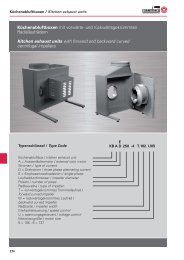
<strong>CompactAIR</strong>-<strong>CENTER</strong><br />
Zuluftgerät / Supply air device<br />
200 PTC 2,4<br />
200 PTC 4,8<br />
280 PTC<br />
355 PTC<br />
355 WW<br />
356 WW<br />
Bediengerät RTE-TR /<br />
Controller RTE-TR<br />
BA039BB05/05/A/4 Rosenberg Ventilatoren<br />
Maybachstraße 1<br />
74653 Künzelsau- Gaisbach<br />
Phone: 07940 / 142 – 0<br />
Fax: 07940 / 142 – 125<br />
Internet: www.rosenberg-gmbh.com<br />
Email: info@rosenberg-gmbh.com
<strong>Betriebsanleitung</strong> <strong>CompactAIR</strong>-Center<br />
2<br />
1 Inhaltsverzeichnis / Index of contents<br />
1 Inhaltsverzeichnis / Index of contents 2<br />
2 Sicherheitshinweise / Safety <strong>instructions</strong> 2<br />
3 Einsatzbedingungen / Conditions of use 3<br />
4 Beschreibung / Description 3<br />
5 Lagerung, Transport / Storage, Transport 4<br />
6 Montage / Installation 4<br />
6.1 Zuluftgerät / Supply air device 4<br />
6.2 Bediengerät RTE-TR / Controller RTE-TR 6<br />
7 Inbetriebnahme / Operation 6<br />
8 Wartung / Maintenance 6<br />
9 Instandsetzung / Repair 7<br />
10 Bediengerät RTE-TR / Controller RTE-TR 9<br />
10.1 Beschreibung / Description 9<br />
10.2 Menüstruktur / structure of menu 10<br />
10.3 Menüsystem / menu system 12<br />
10.4 Fehlermeldungen / error massages 16<br />
11 Busverdrahtung / Bus wiring 20<br />
12 Anhang Anschlussbilder / Appendix: connection diagrams 23<br />
13 Konformitätserklärung / Declaration of conformity 27<br />
2 Sicherheitshinweise / Safety <strong>instructions</strong><br />
Folgende Symbole weisen Sie auf<br />
bestimmte Gefährdungen hin oder geben<br />
Ihnen Hinweise zum sicheren Betrieb.<br />
Achtung! Gefahrenstelle!<br />
Sicherheitshinweis!<br />
Rosenberg - Zuluftgeräte sind nach<br />
dem Stand der Technik zum<br />
Zeitpunkt der Auslieferung<br />
hergestellt!<br />
Umfangreiche Material-, Funktions-<br />
und Qualitätsprüfungen sichern<br />
Ihnen einen hohen Nutzen und<br />
lange Lebensdauer! Trotzdem<br />
können von diesen Geräten<br />
Gefahren ausgehen, wenn sie von<br />
unausgebildetem Personal<br />
unsachgemäß oder nicht zum<br />
bestimmungsgemäßen Gebrauch<br />
eingesetzt werden.<br />
Gefahr durch elektrischen Strom<br />
oder hohe Spannung!<br />
Es ist grundsätzlich verboten,<br />
Arbeiten an unter Spannung<br />
stehenden Teilen durchzuführen.<br />
Schutzart des geöffneten Gerätes<br />
ist IP 00! Gefährliche Spannungen<br />
können direkt berührt werden.<br />
Während des Betriebes muss das<br />
Gerät geschlossen sein.<br />
Spannungsfreiheit muss mit einem<br />
zweipoligem Spannungsprüfer<br />
kontrolliert werden.<br />
The following symbols refer to particular<br />
dangers or give advice on safe operation.<br />
Attention! Danger! Safety advice!<br />
Rosenberg supply air devices are<br />
produced in accordance to the<br />
latest technical standards and our<br />
quality assurance programme<br />
which includes material and<br />
function tests ensures that the final<br />
product is of high quality and<br />
durability. Never the less these fans<br />
can be dangerous if they are not<br />
used and installed correctly,<br />
according to the <strong>instructions</strong><br />
Danger from electric current or high<br />
voltage!<br />
It is strictly forbidden for work to be<br />
carried out on any components<br />
while they are connected to live<br />
voltage. The open equipment is<br />
protected to IP00! It is possible to<br />
come into direct contact with<br />
dangerous voltages.<br />
During operation the equipment<br />
must be closed.<br />
Check to ensure voltage is not<br />
applied to input terminals prior to<br />
commencing work with controller.
<strong>Operating</strong> <strong>instructions</strong> for <strong>CompactAIR</strong>-Center<br />
Vorsicht! Heiße Oberfläche! Caution! Hot surface<br />
Wichtige Hinweise, Informationen Important <strong>instructions</strong>, information<br />
Lesen Sie vor der Montage des<br />
Zuluftgerätes diese<br />
<strong>Betriebsanleitung</strong> aufmerksam<br />
durch!<br />
3 Einsatzbedingungen / Conditions of use<br />
Ventilator fan<br />
Die Zuluftgeräte eignen sich zur<br />
Förderung von:<br />
sauberer Luft<br />
wenig staub- und fetthaltiger Luft<br />
leicht aggressiven Gasen und<br />
Dämpfen<br />
max. Fördermitteltemperatur 40°C<br />
Medien bis zur max. Luftdichte von<br />
1,3 kg/m 3<br />
Medien bis zur max. Feuchte von<br />
95 %<br />
Before installing and operating this<br />
fan please read this <strong>instructions</strong><br />
carefully!<br />
Heizregister Hot-water register<br />
Bedingungen für maximale Heizleistung :<br />
sauberes Wasser<br />
Wasserdurchfluss 1,3 m³/h<br />
Vorlauftemperatur 80°C<br />
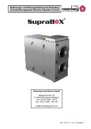
4 Beschreibung / Description<br />
Das Zuluftgerät wurde speziell zur<br />
Beheizung und Belüftung von Räumen und<br />
Gebäuden entwickelt. Die Montage dieser<br />
Geräte kann an der Wand, am Boden, oder<br />
an der Decke erfolgen. Durch die<br />
Verwendung des Außenläufermotors als<br />
Ventilatorantrieb eines<br />
rückwärtsgekrümmten Laufrades und den<br />
Einbau in ein geräuschgedämmtes<br />
Gehäuse, bieten sich entscheidende<br />
technische Vorteile, im Bereich der<br />
Geräuschimmission. Die eingebauten<br />
Ventilatoren sind fünfstufig steuerbar. Die<br />
Heizung ist mit PTC- Elementen oder einem<br />
Warmwasser-Heizregister bestückt. Ein<br />
Filter der Klasse EU4 ist über<br />
Einschubschienen leicht auszuwechseln.<br />
Als Zubehör wird ein Regelungsgerät mit<br />
Temperaturregelung, sowie 5-stufigem<br />
Drehzahlsteuerung des Ventilator<br />
angeboten, des weiteren sind<br />
Verbindungsmanschetten und<br />
Rückschlagklappen lieferbar.<br />
Supply air device can be used for<br />
ventilation of:<br />
- clean air<br />
- slightly dusty and greasy air<br />
- slightly aggressive gases and<br />
fumes<br />
-max. media temperature 40°C<br />
media up to an atmospheric<br />
density of 1,3 kg/m³<br />
- media up to a max. humidity of<br />
95%<br />
Condition for maximum heating power :<br />
- clean water<br />
- water circulation 1,3 m³/h<br />
- temperature of water entry 80°C<br />
Supply air devices were specifically<br />
designed for the heating and ventilation of<br />
rooms and buildings. This type of<br />
equipment may either be mounted on the<br />
wall, on the bottom and ceiling. The<br />
utilization of an external rotor motor as a<br />
fan drive with backward curved impellers<br />
and the installation in a silencing case,<br />
presenting decisive technical advantages in<br />
the zone of noise emission. The installed<br />
fans in fife steps controllable. The heating is<br />
fitted with PTC-elements or with a hot-water<br />
register. A filter of class EU4 can be<br />
changed easily with plug-in rails.<br />
Controllers with temperature control and 5step<br />
speed regulation of the fan are<br />
available as accessories. Additional<br />
connection collars and recoil flaps are also<br />
available.<br />
3
<strong>Betriebsanleitung</strong> <strong>CompactAIR</strong>-Center<br />
4<br />
5 Lagerung, Transport / Storage, Transport<br />
Lagern Sie das Zuluftgerät in seiner<br />
Originalverpackung trocken und<br />
wettergeschützt.<br />
Decken Sie offene Paletten mit<br />
Planen ab und schützen Sie die<br />
Geräte vor Schmutzeinwirkung<br />
(z.B. Späne, Steine, Draht usw.).<br />
Halten Sie Lagertemperaturen<br />
zwischen - 30 °C und + 40 °C ein.<br />
Bei Lagerzeiträumen von über 1<br />
Jahr prüfen Sie vor der Montage<br />
die Leichtgängigkeit der Lager<br />
( Drehen von Hand).<br />
Transportieren Sie das Zuluftgerät<br />
mit geeigneten<br />
Lastaufnahmemitteln und beachten<br />
Sie die Körperlichen Hebekräfte<br />
(⇒ Gewicht lt. Typenschild).<br />
Vermeiden Sie Beschädigungen<br />
des Gehäuses.<br />
Verwenden Sie geeignete<br />
Montagehilfen wie z.B.<br />
vorschriftsmäßige Gerüste<br />
6 Montage / Installation<br />
6.1 Zuluftgerät / Supply air device<br />
Montage und Elektroarbeiten nur<br />
durch ausgebildetes und<br />
eingewiesenes Fachpersonal und<br />
nach den jeweils zutreffenden<br />
Vorschriften!<br />
Es wird eine Absicherung gemäß<br />
VDE 0550, Teil 1, § 6 über<br />
Kurzschluss - Schutzsicherungen<br />
empfohlen.<br />
Für alle Baugrößen For all sizes<br />
Das Zuluftgerät an den beiden<br />
jeweils stirnseitigen<br />
Befestigungsstellen mit Schrauben<br />
M8 und geeigneten<br />
Befestigensmitteln auf tragfähigem<br />
Untergrund oder Konsolen<br />
montieren.<br />
Die Einbaulage ist beliebig, muss<br />
jedoch das Öffnen des<br />
Wartungsdeckels ermöglichen!<br />
Rohrsystem entweder direkt auf die<br />
Anschlussflansche des<br />
Zuluftgerätes aufstecken oder mit<br />
Verbindungsmanschetten<br />
befestigen!<br />
Die Verbindungsmanschetten<br />
vermindern die<br />
Körperschallübertragung erheblich.<br />
Store the supply air device in a dry<br />
place and weather protected in its<br />
original packing.<br />
Cover open pallets with a tarpaulin<br />
and protect the devices against<br />
penetration by dirt (e.g. stones,<br />
splinters, wires, etc.).<br />
Keep storage temperatures<br />
between - 30 °C and + 40 °C.<br />
With storage times of more than 1<br />
year please check the bearings on<br />
soft running before mounting<br />
(→turn by hand)<br />
Transport the fan with suitable<br />
load-bearing means and consider<br />
the physical lifting capacities<br />
(⇒ weight as shown on the data<br />
plate).<br />
Avoid distortion of casing or other<br />
damage.<br />
Use suitable assembling means<br />
such as e.g. scaffolds conforming<br />
to specifications.<br />
Installation and electric work only by<br />
skilled and experienced specialist<br />
workers and in accordance with<br />
applicable regulations!<br />
We recommend a protection fuse<br />
according to VDE 0550, part 1 § 6<br />
about short-circuit safety fuses.<br />
Supply air device install on both<br />
front ends of the mounting places<br />
with screws M8 and suitable<br />
fasteners on load-carrying bottom or<br />
consoles.<br />
The build-in position is any, but has<br />
to be possible to open the<br />
maintenance cap.<br />
Tube system weather mount on the<br />
connecting flange directly or fasten<br />
with connecting collars<br />
connecting collars decrease the<br />
impact noise transfer
Wartungsdeckel öffnen.<br />
Lüfterrad per Hand einige<br />
Umdrehungen durchdrehen und<br />
Leichtgängigkeit prüfen<br />
Die Kabel sind ordnungsgemäß in<br />
den Anschlussraum einzuführen<br />
und abzudichten.<br />
Elektroanschluss nach technischen<br />
Anschlussbedingungen und den<br />
einschlägigen Vorschriften lt.<br />
beigefügtem Klemmenplan im<br />
Anschlusskasten am Gehäuse oder<br />
im Anhang Seite 23 / 24.<br />
Optional:<br />
Beim Anschluss eines<br />
Abluftventilators ist die Brücke Tk<br />
mit dem Thermokontakt des<br />
Ventilators auszutauschen<br />
Beim Anschluss eines<br />
Freigabekontaktes ist die Brücke<br />
Fg mit diesem auszutauschen<br />
Zur Installation Kabel lt. Kabelplan<br />
im Anhang Seite 25 verwenden<br />
<strong>Operating</strong> <strong>instructions</strong> for <strong>CompactAIR</strong>-Center<br />
Open the maintenance cap<br />
Impeller turn through some<br />
revolutions by hand and prove ease<br />
of steering<br />
introduce cable in terminal box<br />
according to the rules and insulate<br />
Electric wiring according to the<br />
technical connecting conditions and<br />
to appropriate regulations in<br />
accordance with clamping- plan<br />
inside of the terminal box on the<br />
housing or in appendix page 23 /24.<br />
Optional:<br />
If you connect a Exhaust fan you<br />
have to change the bridge Tk with<br />
the thermal contacts for motor<br />
protection<br />
If the release contact will be used,<br />
you have to change it with the<br />
bridge Fg.<br />
For installation use cables in<br />
accordance with the wiring layout at<br />
appendix page 25<br />
Zusätzlich für Baugröße 355 WW Additional for size 355WW<br />
Die Hydraulikeinheit bestehend aus<br />
Pumpe, Ventil, Stellantrieb und<br />
Verrohrung ist im Abstand von<br />
maximal 1m an das Heizregister<br />
anzuschließen.(Hydraulische<br />
Schaltung lt. Schaltplan im Anhang<br />
Seite 26)<br />
Beim Anschluss des Warmwasser-<br />
Heizregisters ist darauf zu achten,<br />
das die Vor- und Rücklaufstutzen<br />
nicht verwechselt werden.<br />
Heizregister bei Systemfüllung mit<br />
Wasser sorgfältig entlüften.<br />
Erforderlichenfalls<br />
Verschraubungen nachziehen.<br />
Wird das Heizregister über Gewinde<br />
an das Rohrgestänge<br />
angeschlossen, so muss an den<br />
Rohrstutzen des Heizregisters beim<br />
festziehen gegengehalten werden<br />
um eine Beschädigung zu vermeiden<br />
The hydraulic unit consist of pump,<br />
valve, servo drive and piping is<br />
connecting to the heater in a<br />
maximum Distance from<br />
1m.(Hydraulic circuit according to<br />
the scheme in Appendix page 26)<br />
Be careful by connecting the hot –<br />
water register. Don’ t confuse the<br />
connections from pre- and setback<br />
piece.<br />
- Carefully dearate the register after<br />
filling with water.<br />
If necessary tight the bolts of hot –<br />
water register once more.<br />
For protecting the heater you have to<br />
holding up the flanged socket.If the<br />
heater is connect to the piping by<br />
thread.<br />
5
<strong>Betriebsanleitung</strong> <strong>CompactAIR</strong>-Center<br />
6<br />
6.2 Bediengerät RTE-TR / Controller RTE-TR<br />
Das Bediengerät RTE-TR nur auf<br />
ebener Fläche montieren und nicht<br />
verspannen!<br />
Die Bediengeräte sind nicht für<br />
Unterputzmontage geeignet<br />
(schlechte Wärmeabführung!)<br />
Elektroanschluss nach technischen<br />
Anschlussbedingungen und den<br />
einschlägigen Vorschriften lt.<br />
beigefügtem Anschlussschema<br />
Seite 21.<br />
Kabel ordnungsgemäß in das<br />
Bediengerät einführen und<br />
abdichten!<br />
Zur Installation Kabel lt. Kabelplan<br />
im Anhang Seite 25 verwenden.<br />
7 Inbetriebnahme / Operation<br />
Zuluftgerät zur Erstinbetriebnahme<br />
vorbereiten<br />
ordnungsgemäße mechanische<br />
Montage?<br />
vorschriftsmäßige elektrische<br />
Installation?<br />
Fremdkörper in Ansaug- und<br />
Ausblasbereich sowie im<br />
Ventilatorraum entfernt?<br />
Heiße Oberflächen der Heizung<br />
gegen Berührung geschützt<br />
(Verbrennungsgefahr und Gefahr<br />
durch elektrische Spannung!),<br />
Eingreifschutz durch<br />
angeschlossenes Rohrnetz und<br />
geschlossenen Gerätedeckel<br />
sicherstellen.<br />
Zuluftgerät in Betrieb nehmen:<br />
korrekte Funktion überwachen<br />
(Laufruhe, Vibration, Unwucht,<br />
Stromaufnahme, evtl.<br />
Steuerbarkeit)<br />
8 Wartung / Maintenance<br />
Im Normalfall sind unsere<br />
Zuluftgeräte mit Ausnahme des<br />
regelmäßigen Filterwechsels<br />
wartungsfrei!<br />
Wartungsarbeiten nur durch<br />
ausgebildetes und eingewiesenes<br />
Fachpersonal und nach den jeweils<br />
zutreffenden Vorschriften!<br />
Installation of controller on uneven<br />
surface will lead to deformation<br />
Do not install flush mounted (bad<br />
heat dissipation). Electric wiring<br />
according to technical wiring -<br />
conditions and relevant regulations<br />
in accordance to the enclosed<br />
wiring diagram page 21<br />
Cables are insert and sealed into<br />
the controller properly<br />
For installation use cabels in<br />
accordance with the wiring layout at<br />
appendix page 25.<br />
Prepare supply air device for first<br />
operation<br />
Correct mechanical installation<br />
Electrical installation in accordance<br />
to regulations<br />
Remove foreign matter from inlet<br />
ant outlet area and from inside of<br />
fan<br />
Are the hot surfaces of PTC –<br />
heating protected against<br />
accidental contact (danger of<br />
severe burns and electric voltage),<br />
secure the engagement protection<br />
through connected network of<br />
pipes and closed equipment cap.<br />
Taking supply air device in<br />
operation:<br />
Observe correct function<br />
(smoothness of running, vibration,<br />
unbalance, current consumption,<br />
possibly controllability)<br />
Our fans are with the exception of<br />
changing filter maintenance free<br />
with normal operation!<br />
Maintenance work only by skilled<br />
and trained specialist workers and in<br />
accordance with applicable<br />
regulations.
Vor allen Wartungsarbeiten<br />
Zuluftgerät vollständig von Netz<br />
trennen Stillstand des Laufrades<br />
abwarten!<br />
gegen Wiedereinschalten sichern!<br />
Heizung abkühlen lassen<br />
Zuluftgeräte reinigen<br />
Ansaugöffnungen reinigen<br />
Lüfterrad reinigen (wenn nötig<br />
Laufrad demontieren)<br />
Heizung reinigen durch Absaugen<br />
oder Ausblasen mittels Pressluft<br />
Filter reinigen/erneuern, das<br />
Bediengerät fordert nach 4400<br />
Betriebsstunden zum Filterwechsel<br />
mit einer Klartextmeldung auf.<br />
Zur Reinigung oder Erneuerung<br />
des Filters, dieses aus den<br />
Einschubschienen ziehen, der<br />
Einbau in umgekehrter<br />
Reihenfolge.<br />
Lüfterrad-, Schaufeln und Lamellen<br />
am Heizregister nicht verbiegen!<br />
Eingreifschutz/Motortragegitter<br />
komplett mit Lüfterrad montieren<br />
( Ringspalt zwischen Flügelrad<br />
Rückwandplatte muss gleichmäßig<br />
sein)<br />
Vorsicht! Es darf keine Flüssigkeit in<br />
das Gehäuseinnere gelangen!<br />
Verwenden Sie nur handelsübliche,<br />
lösungsmittelfreie Reinigungsmittel<br />
unter Beachtung der<br />
vorgeschriebenen<br />
Sicherheitsmaßnahmen und<br />
verwenden Sie keine kratzenden und<br />
schabenden Werkzeuge<br />
(Oberflächenschutz wird zerstört!)<br />
Allgemeine Kontrollen<br />
Lagerspiel zu groß?<br />
Schmiermittel an Lager<br />
ausgetreten?<br />
Oberflächenschutz angegriffen (<br />
Fördermedium zu aggressiv!)?<br />
ungewöhnliche Betriebsgeräusche?<br />
9 Instandsetzung / Repair<br />
Verwenden Sie nur von uns geprüfte<br />
und freigegebene Original-<br />
Ersatzteile!<br />
<strong>Operating</strong> <strong>instructions</strong> for <strong>CompactAIR</strong>-Center<br />
Before any maintenance work is<br />
undertaken disconnect fan from<br />
mains supply! Wait until impeller is<br />
stationary!<br />
Make sure that a restart is<br />
impossible!<br />
Allow the PTC – heater to cool down.<br />
Cleaning the supply air device<br />
clean the intake openings<br />
clean the fan impeller ( if required,<br />
remove the impeller)<br />
clean the PTC- heater / either by<br />
vacuuming it or blowing it put with<br />
compressed air<br />
cleaning/ replacing the filter<br />
to clean or replace the filter, pull<br />
out of the rails. Reverse the order<br />
for the installation of the filter.<br />
Do not bend or distort the fan<br />
impeller, vanes and fins of the<br />
heating register!<br />
Install the tamper protection/ motor<br />
support grid together with the fan<br />
impeller ( make sure that the<br />
annular gap between the impeller<br />
and the back wall is uniform!)<br />
Attention! Liquids must not enter<br />
into the casing!<br />
Only use usual commercial solventfree<br />
cleaning material paying<br />
attention to the prescribed safety<br />
measures and do not use any<br />
abrasive tools (surface protection<br />
will be destroyed!)<br />
General controls<br />
bearing play too large?<br />
grease leaking on bearings?<br />
surface protection affected (<br />
medium to be ventilated too<br />
aggressive!)?<br />
unusual operation noise?<br />
Only use original spare parts<br />
manufactured and supplied by<br />
Rosenberg!<br />
7
<strong>Betriebsanleitung</strong> <strong>CompactAIR</strong>-Center<br />
8<br />
Instandsetzungsarbeiten nur durch<br />
ausgebildetes und eingewiesenes<br />
Fachpersonal und nach den jeweils<br />
zutreffenden Vorschriften!<br />
Vor allen Wartungsarbeiten<br />
Zuluftgerät vollständig von Netz<br />
trennen Stillstand des Laufrades<br />
abwarten!<br />
gegen Wiedereinschalten sichern!<br />
Heizung abkühlen lassen<br />
Motorlüfterrad wechseln<br />
Elektroanschluss des Motors<br />
abklemmen<br />
Motoraufhängung lösen und<br />
komplett mit Motorlüfterrad<br />
herausziehen<br />
Motortragegitter von Motorlüfterrad<br />
demontieren.<br />
Neues Motorlüfterrad auf<br />
Motortragegitter montieren, in<br />
vorheriger Position festschrauben<br />
Elektroanschluss des Motors<br />
anklemmen ( “Montage“)<br />
PTC - Heizung wechseln<br />
Befestigungsbügel über Heizung<br />
lösen<br />
Elektroanschluss der Heizung<br />
lösen<br />
Die PTC- Heizung kann<br />
entnommen werden.<br />
Neue Heizung einsetzen<br />
Zusammenbau in umgekehrter<br />
Reihenfolge (→ “Montage“)<br />
Warmwasser-Heizregister wechseln<br />
Rohranschlüsse der Stutzen lösen<br />
Frostschutzfühler lösen und durch<br />
die Befestigungsbleche ziehen.<br />
Seitliche Befestigungsbleche lösen<br />
Das Warmwasser-Heizregister<br />
kann entnommen werden.<br />
Neue Heizung einsetzen<br />
Zusammenbau in umgekehrter<br />
Reihenfolge (→ “Montage“)<br />
Korrekten Einbau kontrollieren<br />
Motorlüfterrad muss sich frei<br />
drehen!<br />
Ringspalt zwischen Flügelrad und<br />
Wandring/Gehäuse muss<br />
gleichmäßig sein<br />
Korrekte Drehrichtung kontrollieren<br />
(→ “Montage“)<br />
Repair work only by skilled and<br />
trained specialist workers and in<br />
accordance with applicable<br />
regulations.<br />
Before any maintenance work is<br />
undertaken disconnect fan from<br />
mains supply! Wait until impeller is<br />
stationary!<br />
Make sure that a restart is<br />
impossible!<br />
Allow the PTC – heater to cool down.<br />
Change of the motor impeller<br />
disconnect electric supply<br />
dismount protection guard<br />
unscrew motor suspension (<br />
protection guard) and pull out<br />
complete with motor impeller.<br />
dismount motor suspension (<br />
protection guard) from motor<br />
impeller mount new motor impeller<br />
on protection guard and secure<br />
with screws.<br />
Connect electric supply of motor<br />
(installation)<br />
Replacing the PTC- heater<br />
disconnect the attached bow above<br />
heater<br />
disconnect the electric wiring of the<br />
heater<br />
remove the PTC- heater<br />
insert the new heater<br />
reverse the order for the assembly<br />
(→ “installation”)<br />
Changing hot – water register<br />
Remove inline connections on the<br />
pieces<br />
Remove frost protection sensor<br />
At the side remove sheet metal<br />
fixing<br />
Take old hot – water register<br />
Insert hot – water register<br />
Assembly in reverse order<br />
(→“installation”)<br />
Verify for correct installation<br />
The fan impeller must rotate freely!<br />
The annular gap between the<br />
impeller and the wall ring/housing<br />
must be uniform<br />
Verify the proper direction of<br />
rotation (→ “Installation”)
10 Bediengerät RTE-TR / Controller RTE-TR<br />
10.1 Beschreibung / Description<br />
PRG<br />
mute<br />
↑<br />
↓<br />
↵<br />
PRG/mute: PRG/mute:<br />
Mit dieser Taste kann zwischen der<br />
Standardanzeige und dem Menü<br />
gewechselt werden, d.h. beim erstmaligen<br />
Betätigen wird das Hauptmenü aufgerufen.<br />
Die Navigation im Menüsystem erfolgt<br />
mittels der Tasten ↑ , ↓ und ↵. Die PRG -<br />
Taste ermöglicht die Rückkehr aus jedem<br />
Untermenü in die Standardanzeige.<br />
Weiterhin kann mit der Taste das<br />
akustische Fehlersignal abgeschaltet<br />
werden<br />
Nach-Oben-Taste: UP - Key:<br />
In der Standardanzeige kann die<br />
Ventilatorstufe erhöht werden, im<br />
Menüsystem ermöglicht sie die Auswahl<br />
von Menüpunkten und bei der Einstellung<br />
von Parametern wird damit der Parameter<br />
erhöht.<br />
<strong>Operating</strong> <strong>instructions</strong> for <strong>CompactAIR</strong>-Center<br />
Nach-Unten-Taste: DOWN - Key:<br />
In der Standardanzeige kann die<br />
Ventilatorstufe verringert werden, im<br />
Menüsystem ermöglicht sie die Auswahl<br />
von Menüpunkten, bei der Einstellung von<br />
Parametern wird damit der Parameter<br />
verringert.<br />
ENTER-Taste<br />
1. Bestätigungstaste, eine getroffene<br />
Auswahl im Menüsystem, bei<br />
Alarmmeldungen oder bei der<br />
Parametrierung wird bestätigt, auch für<br />
Parameter, die nicht verändert wurden, um<br />
zum nächsten Parameter zu gelangen.<br />
2. ON/OFF - Taste, in der Standardanzeige<br />
kann die Anlage ein- bzw. ausgeschaltet<br />
werden.<br />
With this key it can be switched between<br />
standard display an menu. By pressing this<br />
key in the standard display, you will reach<br />
the main menu. Navigation is possible with<br />
the two cursor keys and the “Enter”-Key.<br />
With PRG – Key you can also get back<br />
from a lower menu to the standard display.<br />
Also acoustical signal can be muted with<br />
this key.<br />
In standard display you can increase fan<br />
level with this key. In lower menus you can<br />
navigate one line upwards or you can<br />
increase parameters in configuration<br />
menus.<br />
In standard display you can decrease fan<br />
level with this key. In lower menus you can<br />
navigate one line downwards or you can<br />
decrease parameters in configuration<br />
menus.<br />
ENTER-Taste<br />
1. With the „Enter“-Key you can confirm a<br />
selection or an alarm message.<br />
2. In the standard display you can switch<br />
the fan ON and OFF.<br />
9
<strong>Betriebsanleitung</strong> <strong>CompactAIR</strong>-Center<br />
10.2 Menüstruktur / structure of menu<br />
10<br />
Anlage ein<br />
CompactAir<br />
RTE-TR Version 1.302<br />
*Aus* Lüfterstufe 0<br />
Raum 21°C Zul. 22°C<br />
PRG<br />
mute<br />
4 sec<br />
↓ ↑ ↵<br />
>Heizsollwert<br />
Filterwechsel<br />
Akustischer Alarm.<br />
Dialogsprache<br />
Interne Parameter<br />
! Achtung !<br />
Die Menüpunkte I-Zeit und<br />
Nachlaufz.Vereisg. sind nur<br />
bei BG 355 WW enthalten<br />
(1)<br />
↓<br />
PRG<br />
mute<br />
↑ ↵<br />
Heizsollwert:<br />
21°C<br />
Filter gewechselt ?<br />
Nein<br />
Akustischer Alarm<br />
*Ein*<br />
Dialogsprache:<br />
Deutsch<br />
Zugangscode:<br />
000<br />
>Ext.Geräte (Slaves)<br />
Min.Begrenz.Zuluft<br />
Min.Begrenz.Ein/Aus<br />
Koeff.Min.Begrenz.<br />
Auswahl Regelung<br />
Prop.Band<br />
I-Zeit<br />
Nachlaufz.Vereisg.<br />
Param.rücksetzen<br />
Liefervariante<br />
(1) Standardanzeige<br />
(2) Wenn in einem Untermenü längere<br />
Zeit keine Eingabe erfolgt, wird<br />
automatisch zur Standardanzeige<br />
zurückgeschaltet<br />
Oder Timeout(2)<br />
↓ ↑ ↵<br />
Geräte-Nr.: >1:Nein<br />
2:Nein 3:Nein<br />
Min.Begrenz.Zuluft:<br />
15°C<br />
Minimalbegrenzung:<br />
*Ein*<br />
Koeff.MinBegrenz.ZL:<br />
-1.5<br />
Auswahl Regelung:<br />
Raumluftregelung<br />
Proportionalband:<br />
6°C<br />
Faktor I-Zeit:<br />
5<br />
Zeit nach Vereisung:<br />
2 min<br />
Parameter rücksetzen<br />
Nein<br />
Liefervariante Nr.:<br />
0
Fan On<br />
CompactAir<br />
RTE-TR Release 1.302<br />
*ON* Fan Level 0<br />
Room 21°C IAir. 22°C<br />
PRG<br />
mute<br />
4 sec<br />
(1)<br />
↓ ↑ ↵<br />
>Heating Rated Value<br />
Filter Changed<br />
Buzzing.<br />
Dialog Language<br />
Internal Parameters<br />
! Attention !<br />
The menus Integral Time and<br />
Defrosting Time are only for<br />
BG 355 WW<br />
↓<br />
PRG<br />
mute<br />
<strong>Operating</strong> <strong>instructions</strong> for <strong>CompactAIR</strong>-Center<br />
↑ ↵<br />
Heating Rated Value:<br />
21 °C<br />
Filter Changed? :<br />
No<br />
Buzzing :<br />
*On*<br />
Dialog Language :<br />
English<br />
Access Code :<br />
000<br />
>Ext.Devices/Slaves<br />
Min.Restrict.I.Air<br />
Min.Restrict.On/Off<br />
Coeff.Min.Limit<br />
Select Regulation<br />
Proportional Band<br />
Integral-Time<br />
Defrosting Time<br />
Parameter Reset<br />
Delivery Variant<br />
(1) Standard Display<br />
(2) If there is no Changing in the<br />
further menu for a longer Time, the<br />
Controller automatically get back to<br />
the standard Display<br />
Or Timeout(2)<br />
↓ ↑ ↵<br />
Device-No.: > 1: No<br />
2: No 3: No<br />
Min.Restrict.I.Air :<br />
15°C<br />
Min. Restriction :<br />
*On*<br />
Coeff.Min.Limit :<br />
-1,5<br />
Select Regulation :<br />
Room Air Regulation<br />
Proportionalband :<br />
6°C<br />
Fact.I-Reg.Time :<br />
5<br />
Defrosting Time :<br />
2 min<br />
Parameter reset :<br />
No<br />
Nein<br />
Delivery Variant :<br />
0<br />
11
<strong>Betriebsanleitung</strong> <strong>CompactAIR</strong>-Center<br />
10.3 Menüsystem / menu system<br />
Startanzeige / starting display<br />
Standardanzeige / standard display<br />
12<br />
CompactAir<br />
RTE-TR Version 1.302<br />
Funktion :<br />
Anzeige für 4 sek. beim Einschalten der<br />
Anlage<br />
*AUS* Lüfterstufe 0<br />
Raum 20°C Zul. 22°C<br />
Funktion :<br />
Standardanzeige mit Anzeige des<br />
Anlagenzustandes und der Lüfterstufe.<br />
Die Raumlufttemperatur und/oder die<br />
Zulufttemperatur werden angezeigt, wenn<br />
die entsprechenden Temperatursensoren<br />
angeschlossen sind.<br />
Taste ↵ :<br />
*EIN*/*AUS* - Schalten (*AUS*: Gerät bleibt<br />
zwar elektrisch eingeschaltet, aber<br />
funktional wird ein AUS-Zustand<br />
angenommen).<br />
*EIN*/*AUS* - Schalten ist nicht möglich,<br />
wenn eine Frostschutzroutine läuft oder<br />
wenn der externe Freigabekontakt geöffnet<br />
ist.<br />
Taste ↑, ↓ :<br />
Lüfterstufe erhöhen oder verringern,<br />
Lüfterstufen 1 ... 5<br />
Taste PRG/mute :<br />
Zugang zu den Parametern<br />
Parametermenü / parameter menu<br />
> Heizsollwert<br />
Filterwechsel<br />
Akustischer Alarm<br />
Dialogsprache<br />
Interne Parameter<br />
Funktion :<br />
Auswahl des gewünschten Parameters<br />
Taste ↑, ↓ :<br />
Menüpunkt wählen (Scrollen)<br />
Taste ↵ :<br />
Auswahl bestätigen<br />
Taste PRG/mute :<br />
Zurück zur Standardanzeige<br />
Anzeige / display<br />
Anzeige / display<br />
Menü / menu<br />
CompactAir<br />
RTE-TR Release 1.302<br />
Function :<br />
Displayed for 4 seconds after supplying the<br />
box with voltage<br />
*OFF* Fan Level 0<br />
Room 20°C IAir 22°C<br />
Function :<br />
Shows activation of fan.<br />
Room air sensor and supply air sensor are<br />
shown if connected.<br />
key ↵ :<br />
*ON*/*OFF* - switch (*OFF*: fan is<br />
deactivated, but box is supplied with<br />
voltage)<br />
Switching *ON*/*OFF* is impossible when<br />
frost protection program is activated or<br />
external release contact is open.<br />
key ↑, ↓ :<br />
Increases or decreases fan level, fan levels<br />
1...5<br />
key PRG/mute :<br />
Access to the parameters<br />
> Heating Rated Value<br />
Filter Changed<br />
Buzzing<br />
Dialog Language<br />
Internal Parameters<br />
Function :<br />
Parameter selection<br />
key ↑, ↓ :<br />
Switch menu (Scroll)<br />
key ↵ :<br />
Confirm selection<br />
key PRG/mute :<br />
Exit to standard display
Unterpunkte Parametermenü / further menus<br />
Heizsollwert :<br />
21 °C<br />
Funktion :<br />
Heizsollwert ändern<br />
Standard : 21°C Grenzen : 10...40°C<br />
Filter gewechselt? :<br />
Nein<br />
Funktion :<br />
JA, wenn Filterwechsel erfolgte.<br />
Standard : Nein Werte : Ja , Nein<br />
Akustischer Alarm :<br />
*Ein*<br />
Funktion :<br />
Akustische Alarmmeldung dauerhaft<br />
aktivieren/deaktivieren.<br />
Standard : Ein Werte : Ein , Aus<br />
Dialogsprache :<br />
Deutsch<br />
Funktion :<br />
Dialogsprache wählen. Danach erfolgt ein<br />
Software Neustart<br />
Standard:Deutsch Werte:Deutsch,Englisch<br />
Zugangscode :<br />
000<br />
Funktion :<br />
Code für den Zugang zu den Internen<br />
Parametern<br />
Standard : 000 Grenzen : 000…999<br />
Aktivierung bei 066<br />
Taste ↑, ↓ :<br />
Wert verändern<br />
Taste ↵ :<br />
Wert bestätigen und zurück zum<br />
Parametermenü<br />
Taste PRG/mute :<br />
Zurück zur Standardanzeige<br />
<strong>Operating</strong> <strong>instructions</strong> for <strong>CompactAIR</strong>-Center<br />
Menü / menu<br />
Heating Rated Value :<br />
21 °C<br />
Function :<br />
Changing heating rated value<br />
Standard : 21°C limits : 10...40°C<br />
Filter Changed? :<br />
No<br />
Function :<br />
YES, if filter was changed<br />
Standard : No Values : Yes , No<br />
Buzzing :<br />
*On*<br />
Function :<br />
Activate/deactivate acoustically error<br />
messages<br />
Standard : On Values : On , Off<br />
Dialog Language :<br />
English<br />
Function :<br />
Switch dialog language. After that occurs a<br />
new start by Software<br />
Standard:German Values:German,English<br />
Access Code :<br />
000<br />
Function :<br />
Code for Access to the internal parameters<br />
Standard : 000 limits : 000…999<br />
Activation with 066<br />
key ↑, ↓ :<br />
Changing values<br />
key ↵ :<br />
Confirm value and get back to parameter<br />
menu<br />
key PRG/mute :<br />
Exit to standard display<br />
13
<strong>Betriebsanleitung</strong> <strong>CompactAIR</strong>-Center<br />
Interne Parametermenü / Internal parameter menu<br />
14<br />
> Ext. Geräte (Slaves)<br />
Min.Begrenz.Zuluft<br />
Min.Begrenz.Ein/Aus<br />
Koeff.Min.Begrenz.<br />
Auswahl Regelung<br />
Prop.Band<br />
I-Zeit<br />
Nachlaufz.Vereisg.<br />
Param. Rücksetzen<br />
Liefervariante<br />
Funktion :<br />
Auswahl des gewünschten Parameters<br />
Taste ↑, ↓ :<br />
Menüpunkt wählen (Scrollen)<br />
Taste ↵ :<br />
Auswahl bestätigen<br />
Taste PRG/mute :<br />
Zurück zur Standardanzeige<br />
Menü / menu<br />
Unterpunkte interne Parameter Menü / further internal menus<br />
Geräte-Nr.: > 1: Nein<br />
2: Nein 3: Nein<br />
Funktion :<br />
Buskonfiguration. Die Slaves 1..3 können<br />
entsprechend ihrer eingestellten Adresse<br />
bzw. Geräte - Nr. (siehe Punkt 11<br />
Busverdrahtung Bild 3) mit Ja angemeldet<br />
und mit Nein abgemeldet werden. Nicht<br />
angemeldete, aber am Bus vorhandene<br />
Slaves werden vom Master ignoriert,<br />
angemeldete, aber am Bus nicht<br />
vorhandene Slaves führen zur<br />
Fehlermeldung.<br />
Min.Begrenz.Zuluft :<br />
15°C<br />
Funktion :<br />
Einstellen der minimalen Zulufttemperatur<br />
Standard : 15°C Grenzen : 10...25°C<br />
Minimalbegrenzung :<br />
*Ein*<br />
Funktion :<br />
Die Minimalbegrenzung aktivieren /<br />
deaktivieren.<br />
Standard : Ein Werte : Ein , Aus<br />
Anm.: Wenn kein Zuluftfühler<br />
angeschlossen ist, oder wenn die Regelung<br />
eine Zuluftregelung ist, wird dieses Menü<br />
inaktiv.<br />
Menü / menu<br />
> Ext. Devices/Slaves<br />
Min.Restrict.I.Air<br />
Min.Restrict.On/Off<br />
Coeff.Min. Limit<br />
Select Regulation<br />
Proportional Band<br />
Integral-Time<br />
Defrosting Time<br />
Parameter Reset<br />
Delivery Variant<br />
Function :<br />
Parameter selection<br />
key ↑, ↓ :<br />
Switch menu (Scroll)<br />
key ↵ :<br />
Confirm selection<br />
key PRG/mute :<br />
Exit to standard display<br />
Device-No.: > 1: No<br />
2: No 3: No<br />
Function :<br />
Bus-configuration. Slaves 1..3 can be<br />
registered with No and Yes according to<br />
their address configuration on the power<br />
unit (11 Bus wiring picture 3). Slave units,<br />
who are not registered, will be ignored by<br />
the master unit. Registered Slave units,<br />
which are not connected produces error<br />
messages in display.<br />
Min.Restrict.I.Air :<br />
15°C<br />
Function :<br />
Changing minimal supply air temperature<br />
Standard : 15°C limits : 10...25°C<br />
Min. Restriction :<br />
*On*<br />
Function :<br />
Activate / Deactivate minimum Restriction<br />
.<br />
Standard : On Values : On , Off<br />
Note: If no supply air sensor is connected,<br />
menu is deactivated
Koeff.MinBegrenz.ZL :<br />
-1,5<br />
Funktion :<br />
Koeffizient zur Berechnung der<br />
Minimalbegrenzung<br />
Standard : -1,5 Grenzen : -1,0...-10<br />
Auswahl Regelung :<br />
Raumluftregelung<br />
Funktion :<br />
Auswahl der Regelung<br />
Standard: Raumluftregelung<br />
Werte: Raumluftregelung, Zuluftregelung<br />
Anm.: Raumluftregelung<br />
Die Raumtemperatur wird geregelt. Wenn<br />
ein Zuluftfühler vorhanden ist und die<br />
Minimalbegrenzung aktiviert ist, bleibt der<br />
Zuluftfühler bis zur Unterschreitung der<br />
Minimalbegrenzung inaktiv. Bei<br />
Unterschreitung wird der<br />
Temperatursollwert unter Berücksichtigung<br />
der Zulufttemperatur berechnet.<br />
Anm.: Zuluftregelung<br />
Die Zulufttemperatur wird geregelt. Ein evtl.<br />
angeschlossener Raumluftfühler wird<br />
ignoriert. Die Minimalbegrenzung ist inaktiv.<br />
Proportionalband :<br />
6°C<br />
Funktion :<br />
Proportionalband für P-Regler<br />
Standard : 6°C Grenzen : 1...20°C<br />
Faktor I-Zeit :<br />
5<br />
Funktion :<br />
Integrationszeitfaktor für I-Regler<br />
Standard : 5 Grenzen : 1...10<br />
Zeit nach Vereisung :<br />
2 min<br />
Funktion :<br />
Mindestlaufzeit der Enteisungsfunktion<br />
nach aufgetretenem Frostalarm.<br />
Standard : 2min Grenzen : 0...60 min<br />
Parameter rücksetzen :<br />
Nein<br />
Funktion :<br />
Parameter Prop. Band, I-Zeit,<br />
Koeff.Min.Begrenz. und Nachlaufz.Vereisg.<br />
werden auf Standardwerte zurückgesetzt.<br />
Danach erfolgt ein Software-Neustart<br />
Standard : Nein Werte : Ja, Nein<br />
<strong>Operating</strong> <strong>instructions</strong> for <strong>CompactAIR</strong>-Center<br />
Coeff.Min.Limit :<br />
-1,5<br />
Function :<br />
Coefficient to compute the minimal<br />
Restriction<br />
Standard : -1,5 limits : -1,0...-10<br />
Select Regulation :<br />
Room Air Regulation<br />
Function :<br />
Switch regulation<br />
Standard : Room Air Regulation<br />
Values : Room Air Regulation, Supply Air<br />
Regulation<br />
Note: Room Air Regulation<br />
The room temperature will be regulate. If<br />
there is a supply air sensor and the minimal<br />
limit is active, the supply air sensor stays<br />
inactive till the temperature is lower than<br />
the minimal limit<br />
Note : Supply air Regulation<br />
The supply air will be regulate. A eventually<br />
connected Room sensor will be ignored.<br />
The minimal Restriction is inactive.<br />
Proportionalband :<br />
6°C<br />
Function :<br />
Proportionalband for P-Regulator<br />
Standard :6°C limits :1 ...20°C<br />
Fact.I-Reg.Time :<br />
5<br />
Function :<br />
Integral Time factor for I-Regulator<br />
Standard :5 limits :1 ...10<br />
Defrosting Time :<br />
2 min<br />
Function :<br />
Minimal Defrosting Time<br />
after Frost Buzzing<br />
Standard : 2min limits : 0...60 min<br />
Parameter reset :<br />
No<br />
Function :<br />
Parameters Proportional Band, Integral-<br />
Time, Coeff.Min.Limit become reset to<br />
standard value. After that occurs a new<br />
start by Software<br />
Standard : No Values : Yes, No<br />
15
<strong>Betriebsanleitung</strong> <strong>CompactAIR</strong>-Center<br />
16<br />
Liefervariante :<br />
0<br />
Funktion :<br />
Zur Änderung der Startanzeige<br />
Danach erfolgt ein Software-Neustart<br />
Standard : 0 Werte : 0, 1<br />
Taste ↑, ↓ :<br />
Wert verändern<br />
Taste ↵ :<br />
Wert bestätigen und zurück zum<br />
Parametermenü<br />
Taste PRG/mute :<br />
Zurück zur Standardanzeige<br />
10.4 Fehlermeldungen / error massages<br />
Alarm an Gerät 0!<br />
Kein Zuluftfühler<br />
Funktion :<br />
Wenn bei Zulufttemperaturregelung kein<br />
Zuluftfühler angeschlossen ist. Anlage<br />
schaltet ab. Fehler muss beseitigt werden,<br />
sonst keine Quittierung möglich.<br />
Alarm an Gerät 0!<br />
Kein Raumluftfühler<br />
Funktion :<br />
Wenn bei Raumtemperaturregelung kein<br />
Raumluftfühler angeschlossen ist. Anlage<br />
schaltet ab. Fehler muss beseitigt werden,<br />
sonst keine Quittierung möglich.<br />
Alarm an Gerät 0!<br />
Sicherh.-Tmp.Begrenz.<br />
Funktion :<br />
Alarm Sicherheitstemperaturbegrenzer<br />
bei Geräten mit Elektroheizung.<br />
Gerät 0 (Master): Anlage schaltet ab.<br />
Fehler muss beseitigt werden, sonst keine<br />
Quittierung möglich.<br />
Gerät 1...3 (Slave): Nur das gemeldete<br />
Gerät schaltet ab. Zur Fehlerbeseitigung<br />
und Quittierung muss das Gerät vom Netz<br />
getrennt werden.<br />
Delivery Variant :<br />
0<br />
Function :<br />
To changing the starting display<br />
After that occurs a new start by Software<br />
Standard : 0 Values : 0, 1<br />
key ↑, ↓ :<br />
Changing values<br />
key ↵ :<br />
Confirm value and get back to parameter<br />
menu<br />
key PRG/mute :<br />
Exit to standard display<br />
Fehlermeldung / error massage<br />
Error on Device 0!<br />
No I.Air Sensor<br />
Function :<br />
No supply air temperature sensor is<br />
connected. Device switches off. Error must<br />
be removed, otherwise reception is<br />
impossible.<br />
Error on Device 0!<br />
No Room Sensor<br />
Function :<br />
No Room temperature sensor is connected.<br />
Device switches off. Error must be<br />
removed, otherwise reception is impossible.<br />
Error on Device 0!<br />
Overheating<br />
Function :<br />
Error message Overheating in exhaust.<br />
Device 0 (Master): Fan switches off. Error<br />
must be removed, otherwise reception is<br />
impossible.<br />
Device 1..3 (Slave): Displayed device is<br />
deactivated. To remove error and receipt<br />
message, you have to disconnect supply<br />
voltage.
Alarm an Gerät 0!<br />
Frostschutz<br />
Funktion :<br />
Frostalarm bei Geräten mit<br />
Warmwasserheizung.<br />
Gerät 0...3 (alle Geräte): Anlage schaltet<br />
ab. Eine Enteisungsfunktion für alle Geräte<br />
wird gestartet. Wenn nach<br />
Enteisungsfunktion Fehler immer noch<br />
vorhanden, erneuter Alarm. Während der<br />
Enteisungsfunktion erscheint alternierend<br />
„FROST“ in der Standardanzeige.<br />
Alarm an Gerät 0!<br />
Filter wechseln<br />
Funktion :<br />
Nur für Gerät 0 (Master): Die Betriebszeit<br />
ohne Filterwechsel (ein halbes Jahr) ist<br />
abgelaufen.<br />
Die Anlage schaltet nicht ab. Die<br />
Fehlermeldung kann quittiert werden.<br />
Wurde Filter nicht gewechselt (Bestätigung<br />
im Menü „Filterwechsel“) erscheint die<br />
Meldung jeweils nach einem Tag erneut.<br />
Alarm an Gerät 0!<br />
Zuluftventilator<br />
Funktion :<br />
Der Thermokontakt Zuluftventilator hat<br />
angesprochen.<br />
Gerät 0 (Master): Anlage schaltet ab.<br />
Fehler muss beseitigt werden, sonst keine<br />
Quittierung möglich.<br />
Gerät 1...3 (Slave): Nur das gemeldete<br />
Gerät schaltet ab. Zur Fehlerbeseitigung –<br />
und Quittierung muss das Gerät vom Netz<br />
getrennt werden.<br />
Alarm an Gerät 0!<br />
Abluftventilator<br />
Funktion :<br />
Der Thermokontakt Abluftventilator hat<br />
angesprochen.<br />
Gerät 0 (Master): Anlage schaltet ab.<br />
Fehler muss beseitigt werden, sonst keine<br />
Quittierung möglich.<br />
Gerät 1...3 (Slave): Nur das gemeldete<br />
Gerät schaltet ab. Zur Fehlerbeseitigung –<br />
und Quittierung muss das Gerät vom Netz<br />
getrennt werden. Fehler wird nach ca. 30<br />
sek. gestörter Kommunikation am Bus<br />
ausgelöst.<br />
<strong>Operating</strong> <strong>instructions</strong> for <strong>CompactAIR</strong>-Center<br />
Error on Device 0!<br />
Frost protection<br />
Function :<br />
Error frost protection with hot-water<br />
heating.<br />
Device 0..3 (all Devices): Device switches<br />
off. Defrosting program for all devices will<br />
be started. If error message is still<br />
displayed after defrosting program has<br />
finished, error message will be displayed<br />
again. During Defrosting program is<br />
activated, display shows “FROST”.<br />
Error on Device 0!<br />
Change Filter<br />
Function :<br />
Only on Device 0 (Master): Operation<br />
period without changing filter is finished<br />
(half a year).<br />
Fan still activated. Error message can be<br />
receipted.<br />
If filter wasn’t changed (reception in menu<br />
“Filter Changed”), display shows message<br />
on every following days.<br />
Error on Device 0!<br />
Supply Fan<br />
Function :<br />
Thermal contact on supply fan is<br />
interrupted.<br />
Device 0 (Master): Fan switches off. Error<br />
must be removed, otherwise reception is<br />
impossible.<br />
Device 1..3 (Slave): Displayed device is<br />
deactivated. To remove error and receipt<br />
message, you have to disconnect supply<br />
voltage.<br />
Error on Device 0!<br />
Extract Fan<br />
Function :<br />
Thermal contact on exhaust fan is<br />
interrupted.<br />
Device 0 (Master): Fan switches off. Error<br />
must be removed, otherwise reception is<br />
impossible.<br />
Device 1..3 (Slave): Displayed device is<br />
deactivated. To remove error and receipt<br />
message, you have to disconnect supply<br />
voltage. Error will be activated after 30<br />
seconds.<br />
17
<strong>Betriebsanleitung</strong> <strong>CompactAIR</strong>-Center<br />
18<br />
Alarm an Gerät 0!<br />
Kommunikationsfehler<br />
Funktion :<br />
Gerät 0 (Master): Die Kommunikation zum<br />
Bedienteil ist gestört. Anlage schaltet ab.<br />
Bei unterbrochener Verbindung zeigt das<br />
Bedienteil „No data! Please check<br />
connection!“ an. Der Fehler muss beseitigt<br />
werden, sonst keine Quittierung möglich.<br />
Bitte die Busverdrahtung überprüfen.<br />
Gerät 1...3 (Slave):<br />
Nur das gemeldete Gerät schaltet ab.<br />
Mögliche Gründe und Fehlerbeseitigung:<br />
Die im Menü angemeldeten Slaves<br />
stimmen nicht mit der realen Konfiguration<br />
(Anzahl der Slaves und Adresseinstellung<br />
am Slave) überein. Bitte Konfiguration<br />
prüfen und ggf. korrigieren.<br />
Ein Slave ist von der Netzeinspeisung<br />
getrennt. Bitte ggf. korrigieren.<br />
Die Busverbindung vom Master zu einem<br />
Slave ist unterbrochen oder verpolt. Bitte<br />
ggf. korrigieren.<br />
Anm.: Wenn eine sehr lange<br />
Busverbindung unterbrochen wird, kann es<br />
sein, dass aufgrund des dann fehlenden<br />
Abschlusswiderstandes die gesamte<br />
Buskommunikation zusammenbricht. Dieser<br />
Fehler wird als Kommunikationsfehler des<br />
Masters gemeldet (Gerät 0).<br />
Alarm an Gerät 0!<br />
Interne Störung<br />
Funktion :<br />
Anlage komplett abschalten und dann<br />
wieder einschalten. Wenn der Fehler häufig<br />
vorkommt, bitte den Service informieren.<br />
Ajhd #+834bnk 65<br />
djdhj 925dßx<br />
Funktion :<br />
Chaotische Anzeige am Bedienteil.<br />
Wahrscheinlich haben mehrere Geräte am<br />
Bus die Adresse 0. Bitte Anlage<br />
ausschalten und Geräteadressen richtig<br />
einstellen.<br />
Funktion :<br />
Keine Anzeige. Die Busverdrahtung ist nicht<br />
in Ordnung oder es befindet sich kein<br />
Master (Adresse 0) am Bus. Bitte<br />
korrigieren.<br />
Error on Device 0!<br />
Communication Error<br />
Function :<br />
Device 0 (Master): Communication error<br />
on control unit. Fan switches off. If it is<br />
disconnected, control unit shows message<br />
“No data! Please check connection!”. Error<br />
must be removed, otherwise reception is<br />
impossible. Please check bus wiring.<br />
Device 1…3 (Slave):<br />
Only the displayed Device is deactivated.<br />
Possible errors and solutions:<br />
Registered slaves do not correspond with<br />
the number of connected power units.<br />
Please check configuration.<br />
One slave is disconnected from supply<br />
voltage.<br />
Bus wiring from master to slave is<br />
disconnected or not correct poled.<br />
Note : If there is a disconnection on a very<br />
long bus wiring the Communication caves<br />
in, because of the terminating resistor. This<br />
error is shown as a Communication error on<br />
Master (Device 0).<br />
Error on Device 0!<br />
Function :<br />
Deactivate complete device and restart. If<br />
error repeats frequently, please contact<br />
service.<br />
Ajhd #+834bnk 65<br />
djdhj 925dßx<br />
Function :<br />
Chaotically display message. It is possible<br />
that more than one device have to port<br />
address 0. Disconnect supply voltage and<br />
reconfigure port addresses.<br />
Function :<br />
No display message. Bus is wrong<br />
connected or no master unit (address 0) is<br />
activated. Please check configuration.
Taste ↑, ↓ :<br />
Keine Funktion<br />
Taste ↵ :<br />
Quittiert Fehlermeldung, die nächste<br />
Fehlermeldung erscheint oder es wird<br />
wieder das Standardmenü angezeigt.<br />
Taste PRG/mute :<br />
Schaltet (für die aktuelle Fehlermeldung)<br />
den Fehlerton ab.<br />
<strong>Operating</strong> <strong>instructions</strong> for <strong>CompactAIR</strong>-Center<br />
key ↑, ↓ :<br />
No function<br />
key ↵ :<br />
With this key you can receipt error<br />
messages, next error messages is shown<br />
or standard display is reactivated.<br />
key PRG/mute :<br />
Switches off current error tone (muting).<br />
19
<strong>Betriebsanleitung</strong> <strong>CompactAIR</strong>-Center<br />
11 Busverdrahtung / Bus wiring<br />
Adresseinstellung Leistungsteil / Configuration on power unit<br />
Adresse: 0=Master Slave 1 Slave 2 Slave 3 Bild 3<br />
(Standard)<br />
Konfiguration: ein Leistungsteil mit einem Bedienteil / Configuration with one controller unit<br />
20<br />
Diese Konfiguration mit der am<br />
Leistungsteil eingestellten Adresse 0<br />
(Master) entspricht der<br />
Standardkonfiguration (Lieferzustand). Das<br />
Bedienteil muss immer angeschlossen sein.<br />
Normale Umgebung / Regular surroundings<br />
In einer Standardumgebung ohne massive<br />
EMV - Störungen kann für die<br />
Busverdrahtung zwischen Leistungsteil und<br />
Bedienteil 4-adriges Fernmeldekabel<br />
(Telefonkabel) AWG 28 nach DIN 47467/6<br />
/7 bis zu einer Gesamtleitungslänge von<br />
100 m verwendet werden. Verdrahtung<br />
nach Bild 4a, es sind keine weiteren<br />
Maßnahmen erforderlich.<br />
The standard configuration is address 0<br />
(Master). You have to use this when you<br />
run only one power unit (Box). The<br />
controller unit have to connected always.<br />
In surroundings with no EMV –<br />
disturbances, you can connect your power<br />
unit and your controller unit with a 4-leaded<br />
telecommunication cable according to AWG<br />
628/DIN 47467/6/7 (max. cable length.<br />
100m). Wiring according to picture 4a.<br />
Bild 4a<br />
Umgebung mit starken EMV – Störungen / Surroundings with highly magnetic emissions<br />
In einer industriellen Umgebung mit starker<br />
EMV - Störeinstrahlung kann es erforderlich<br />
sein, für die Busverdrahtung 2-paariges,<br />
symmetrisches 120 Ohm<br />
Datenübertragungskabel für EIA RS-485<br />
AWG 28...22 mit Gesamtabschirmung zu<br />
verwenden (z.B. Belden Wire & Cable<br />
Company: Typ 3107A oder Typ 8132).<br />
Verdrahtung nach Bild 4b, maximale<br />
Gesamtleitungslänge 100 m.<br />
german – english:<br />
Leistungsteil – power unit<br />
Bedienteil – controller unit<br />
Rückseite – back side<br />
Standardverdrahtung – standard<br />
wiring<br />
In surroundings with high EMV – pollution, it<br />
is necessary to use shaded, symmetrical, 2leaded<br />
120 Ohm telecommunication cable<br />
according to EIA RS-485 AWG 28...22<br />
(max. cable length 100m) (for example:<br />
Belden Wire & Cable Company Type 3107<br />
A or Type 8132). Wiring according to<br />
picture 4b.<br />
german – english:<br />
Leistungsteil – power unit<br />
Bedienteil – controller unit<br />
Rückseite – back side<br />
Schirm - shade<br />
Bild 4b
<strong>Operating</strong> <strong>instructions</strong> for <strong>CompactAIR</strong>-Center<br />
german german – english: english english english<br />
Busanschluss Variante<br />
Elektroheizregister –BUS wiring on<br />
PTC Boxes<br />
Bedienteil – controller unit<br />
offen – open<br />
geschl. - closed<br />
21
<strong>Betriebsanleitung</strong> <strong>CompactAIR</strong>-Center<br />
Konfiguration: Maximal vier Leistungsteile mit einem Bedienteil am Bus (Netzwerk) /<br />
Configuration: Max. four power units with one controller unit (Network)<br />
22<br />
Folgende Hinweise sind zu beachten: Pay attention on the following information:<br />
Alle Arbeiten am Netzwerk müssen im<br />
stromlosen Zustand aller Geräte erfolgen!<br />
Es können nur Leistungsteile vom<br />
gleichen Heizungstyp an einem Bus<br />
angeschlossen werden (alle für<br />
Elektroheizregister oder alle für<br />
Warmwasserheizung).<br />
Jedes Leistungsteil kann grundsätzlich<br />
als Master (der eigentliche Regler mit<br />
Temperaturfühler) oder als Slave<br />
(„Leistungsfolger“, übernimmt die<br />
Stellwerte für Ventilatoren und Heizung<br />
vom Master, benötigt keine<br />
Temperaturfühler) eingestellt werden.<br />
Die Unterscheidung, welches<br />
Leistungsteil Master und welches Slave<br />
ist, erfolgt ausschließlich über die<br />
Adresseinstellung (Punkt 11, Bild 3).<br />
Der einzige Master am Bus muss immer<br />
auf die Adresse 0 eingestellt werden.<br />
Das einzige Bedienteil am Bus muss<br />
immer angeschlossen sein.<br />
Alle maximal 3 Slaves am Bus müssen<br />
auf Adressen verschieden von 0 und<br />
verschieden voneinander eingestellt<br />
werden, also z.B.:<br />
Master: Adresse 0 (immer)<br />
Slave 1: Adresse 1<br />
Slave 2: Adresse 2<br />
Die jeweilige Adresseinstellung wird beim<br />
elektrischen Einschalten des Gerätes<br />
wirksam und kann während des<br />
Betriebes nicht verändert werden.<br />
Die Busverdrahtung muss entsprechend<br />
Bild 4a oder 4b erfolgen. Bitte die<br />
Anordnung von Slaves, Master und<br />
Bedienteil am Bus beachten!<br />
Die im Lieferzustand der Leistungsteile<br />
aufgesteckte Kurzschlussbrücke JP1<br />
(über der Busanschlussklemme) muss<br />
bei allen Busteilnehmern außer beim<br />
letzten Slave am Busende entfernt<br />
werden (auch beim Master).<br />
Die richtig adressierten und korrekt am<br />
Bus angeschlossenen Slaves müssen<br />
nach dem Einschalten der Anlage<br />
angemeldet werden, siehe Menüpunkt<br />
„Ext. Geräte (Slaves)“. Ohne die<br />
Anmeldung wird davon ausgegangen,<br />
dass sich keine Slaves am Bus befinden.<br />
Adresseinstellung und Busverdrahtung<br />
müssen fehlerfrei sein, sonst ist die<br />
Funktion der Anlage nicht gewährleistet<br />
und dauerhafte Beschädigungen sind<br />
möglich.<br />
Before working on the network, supply<br />
voltage must be switched off on all<br />
boxes!<br />
You can only use power units from the<br />
same heating type together on one<br />
Bus (either PTC heating or hot-water)<br />
Every power unit can used as a master<br />
(temperature sensor is necessary) or a<br />
slave (copies configuration for fans<br />
and heater from master, no<br />
temperature sensor is necessary).<br />
The difference in configuration, which<br />
power unit is master or slave, is only<br />
possible through the address<br />
configuration (11, picture 3)<br />
The Master must have the port<br />
address 0.<br />
The controller unit must be connected<br />
with the master unit.<br />
Slaves must have different addresses.<br />
For exp.:<br />
Master: address 0 (always)<br />
Slave 1: address 1<br />
Slave 2: address 2<br />
Address configuration will be activated<br />
by switching on the supply voltage and<br />
cannot be changed during the<br />
operation.<br />
Bus wiring according to picture 5a or<br />
5b. Please pay attention on connecting<br />
the slaves, master and controller units!<br />
Jumper JP1 must be removed from all<br />
power units, except on the last slave<br />
unit.<br />
Correct addressed and connected<br />
slaves must be registered after<br />
activating the box. Without this<br />
registration, the controller unit doesn’t‘<br />
t know that slaves are activated.<br />
Configuration of Bus wiring must be<br />
faultless, otherwise there is no<br />
guarantee.
<strong>Operating</strong> <strong>instructions</strong> for <strong>CompactAIR</strong>-Center<br />
12 Anhang Anschlussbilder / Appendix: connection diagrams<br />
Anschluss Kundenseite Variante Elektroheizung / Wiring diagram for 200, 280 & 355 PTC<br />
german – english:<br />
Einspeisung – supply lines<br />
Klappe – flap<br />
Abluftventilator – exhaust fan<br />
Thermokontakt Abluftventilator –<br />
Thermal contacts of exhaust fan<br />
Zuluftfühler – Supply air sensor<br />
Raumluftfühler – Room sensor<br />
Freigabe – release contact<br />
Adresse - address<br />
Vorsicht!<br />
Bei der 200 PTC 2,4 kW Box ist<br />
nur 1~ 230V notwendig! Keine 3~<br />
400V!<br />
Attention!<br />
Supply voltage on 200 PTC 2,4 kW<br />
Box is only 230V, not 400V!<br />
23
<strong>Betriebsanleitung</strong> <strong>CompactAIR</strong>-Center<br />
Anschluss Kundenseite Warmwasservariante / Wiring diagram for 355 WW<br />
german – english:<br />
Einspeisung – supply lines<br />
Klappe – flap<br />
Abluftventilator – exhaust fan<br />
Thermokontakt Abluftventilator –<br />
Thermal contacts of exhaust fan<br />
Zuluftfühler – Supply air sensor<br />
Raumluftfühler – Room sensor<br />
Freigabe – release contact<br />
Warmwasserventil – hot-water<br />
valve<br />
Gehäuse – Box<br />
Pumpe/Magnetventil –<br />
pump/magnetic valve<br />
Adresse - address<br />
24
Kabelplan mit allen Komponenten<br />
<strong>Operating</strong> <strong>instructions</strong> for <strong>CompactAIR</strong>-Center<br />
Leitungen zum <strong>CompactAIR</strong> – Center - Komponenten Kabelart Querschnitt [mm²]<br />
Zuleitung 200PTC4,8, 280PTC, 355PTC<br />
Zuleitung 200PTC2,4, 355WW<br />
NYM-J<br />
NYM-J<br />
5 x 2,5<br />
3 x2,5<br />
Raumtemperaturfühler LIYCY 2 x 0,5<br />
Bediengerät RTE-TR, Fernmeldekabel (Telefonkabel)<br />
AWG28 nach DIN 47467/6/7 max. Leitungslänge 50m<br />
Für Umgebungen mit starker EMV - Störeinstrahlung ist<br />
symmetrisches 120 Ohm Datenkabel mit Schirm zu<br />
verwenden. Max. Leitungslänge 100m.<br />
2-paarig<br />
Freigabekontakt LIYCY 2 x 0,5<br />
Abluftventilator NYM-J 3 x 1,5 (5x1,5)<br />
Zuluftklappe NYM-J 3 x 1,5<br />
Warmwasserventil LIYCY 3 x 0,5<br />
Pumpe WW/ Magnetventil NYM-J 3x1,5<br />
Zuluftfühler empfohlen bei 355 WW LIYCY 2x0,5<br />
Wiring layout for all components<br />
Lines to <strong>CompactAIR</strong> – Center components Kind of cable Cross section [mm²]<br />
Supply line 200PTC4,8, 280PTC, 355PTC<br />
Supply line 200PTC2,4, 355WW<br />
NYM-J<br />
NYM-J<br />
5 x 2,5<br />
3 x2,5<br />
Sensor of room temperature LIYCY 2 x 0,5<br />
Controller RTE-TR, telecommunication cable<br />
AWG28 according DIN 47467/6/7 max. cable length 50m<br />
In surroundings with EMV – disturbances it is advisable to<br />
connect the controller unit with shaded 120 Ohm data cable.<br />
Max. cable length 100m.<br />
2-leaded<br />
Release contact LIYCY 2 x 0,5<br />
Exhaust fan NYM-J 3 x 1,5 (5x1,5)<br />
Flap of air intake NYM-J 3 x 1,5<br />
Hot-water valve LIYCY 3 x 0,5<br />
Pump WW/ magnetic valve NYM-J 3x1,5<br />
Sensor of air intake temp. recommended on 355 WW LIYCY 2x0,5<br />
GEWICHTSTABELLE: / WEIGHT CHART:<br />
Bgr.<br />
Bgr.<br />
Bgr.<br />
Bgr.<br />
Typ<br />
Type<br />
200PTC<br />
280PTC<br />
355PTC<br />
355WW<br />
Gewicht in kg<br />
approx. weight in kg<br />
26<br />
37<br />
53<br />
52<br />
25
<strong>Betriebsanleitung</strong> <strong>CompactAIR</strong>-Center<br />
Schaltplan für Hydraulische Schaltung / diagram for hydraulic circuit<br />
Es gibt grundsätzlich für die klimatechnische Anwendung 2<br />
Grundschaltungen, wie das 3-Wege-Mischerventil in die<br />
Hydraulik integriert wird. Das ist zum ersten die<br />
Beimischschaltung, bei der das Ventil in der Vorlaufseite<br />
eingebaut ist und die Einspritzschaltung, in der das Ventil<br />
im Rücklauf sitzt.<br />
M<br />
-<br />
B<br />
26<br />
+<br />
A<br />
M<br />
AB<br />
In principle there are 2 circuits for climatic applications,<br />
how to integrate the valve into the hydraulic. They are at<br />
first the admixture circuit with the valve in forward<br />
movement pipe and the injection circuit with the valve in<br />
return pipe<br />
Beimischschaltung Admixture Circuit<br />
Funktion :<br />
Bei der Beimischschaltung wird durch die<br />
Umwälzpumpe ständig die vom Heizregister<br />
benötigte Wassermenge gefördert und nur<br />
ein von der Ventilstellung bestimmter Teil<br />
von Heißwasser beigemischt. Es ergibt sich<br />
somit eine über die gesamte Heizfläche<br />
konstante Temperatur. Das Regelverhalten<br />
ist somit besser. Außerdem wird das Risiko<br />
der Frostgefahr bei laufender Pumpe<br />
kleiner, da durch die ständige Zirkulation<br />
und dem erhöhten Druck der Gefrierpunkt<br />
des Wassers sinkt.<br />
Einspritzschaltung (Empfehlung) Injection circuit<br />
Funktion :<br />
Der Vorteil der Einspritzschaltung<br />
gegenüber der Beimischschaltung besteht<br />
dann, wenn die Wege zwischen<br />
Mischerventil und Heizkessel sehr groß<br />
sind. Weil die Pumpe vor dem Ventil sitzt<br />
steht am Ventil ständig heißes Wasser an<br />
und kann bei Bedarf sofort an das<br />
Heizregister weitergeleitet werden. Bei der<br />
Beimischschaltung kann es vorkommen,<br />
dass das Wasser in der Leitung zum Ventil<br />
abkühlt, so dass bei Wärmebedarf erst die<br />
Zuleitung überbrückt werden muss.<br />
( Achtung die Einspritzschaltung ist mittels<br />
Drosseln anlagenspezifisch einzuregulieren)<br />
Hydraulikinstallation nur durch<br />
ausgebildetes und eingewiesenes<br />
Fachpersonal und nach den jeweils<br />
zutreffenden Vorschriften! Die Auswahl<br />
der Hydraulikschaltung muss<br />
anlagenbezogen erfolgen. Bei<br />
Fernwärme Rücksprache mit EVU<br />
bezüglich der Hydraulikschaltung.<br />
Function :<br />
At the admixture circuit the pump always<br />
extracts the body of water, witch is needed<br />
by the heater. And only a part of hot water<br />
gets admixed, witch is determine by the<br />
valve. So there is a constant temperature<br />
over the whole heater and the regulation<br />
works better. And the danger of freezing is<br />
also reduced, because of the constant<br />
circulation and the higher pressure. The<br />
frosting point of the water rice down.<br />
Function :<br />
The advantage of the injection circuit<br />
against the admixture circuit is when the<br />
ways between valve and boiler are very<br />
long. Because the pump is mount before<br />
valve so there is always hot water on the<br />
valve, witch can pass on to the heater. At<br />
the admixture circuit the water in the pipe to<br />
the valve may be cools down. In this case<br />
the the feed pipe must be bridged<br />
(Attention the injection circuit is specifically<br />
for each installation to regulate in by<br />
throttles)<br />
Hydraulic instalation work only by<br />
skilled and trained specialist workers<br />
and in accordance with applicable<br />
regulations.
<strong>Operating</strong> <strong>instructions</strong> for <strong>CompactAIR</strong>-Center<br />
13 Konformitätserklärung / Declaration of conformity<br />
27
<strong>Betriebsanleitung</strong> <strong>CompactAIR</strong>-Center<br />
KUNDENDIENST, HERSTELLERADRESSE / SERVICE ADDRESS OF PRODUCER<br />
Rosenberg-Produkte unterliegen einer ständigen<br />
Qualitätskontrolle und entsprechen den geltenden<br />
Vorschriften.<br />
Für alle Fragen, die Sie im Zusammenhang mit unseren<br />
Produkten haben, wenden Sie sich bitte an den Ersteller<br />
Ihrer lufttechnischen Anlage, an eine unserer<br />
Niederlassungen oder direkt an:<br />
28<br />
Rosenberg Ventilatoren GmbH<br />
Maybachstraße 1<br />
D-74653 Künzelsau-Gaisbach<br />
Zentrale Tel.: 07940/142-0<br />
Telefax: 07940/142-125<br />
Rosenberg products are subject to steady quality controls<br />
and are in accordance to valid regulations.<br />
In case you have any questions with regard to our products,<br />
please contact either your constructor of your air handling<br />
unit or directly to one of our distributors: