SALZSTOCK ETZEL - KBB Underground Technologies GmbH
SALZSTOCK ETZEL - KBB Underground Technologies GmbH
SALZSTOCK ETZEL - KBB Underground Technologies GmbH

Sie wollen auch ein ePaper? Erhöhen Sie die Reichweite Ihrer Titel.
YUMPU macht aus Druck-PDFs automatisch weboptimierte ePaper, die Google liebt.
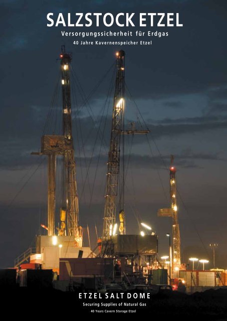
<strong>SALZSTOCK</strong> <strong>ETZEL</strong><br />
V erso r g u n gssicherhe it für E r dga s<br />
40 Jahre Kavernenspeicher Etzel<br />
<strong>ETZEL</strong> S AL T D OME<br />
S ecuring Supplies of Natural Gas<br />
40 Years Cavern Storage Etzel
The company<br />
The company was founded in 1978 by Dipl.-Ing. Juergen<br />
Becker and has been active mainly in the design of<br />
national projects but also international projects.<br />
rm employs more than 90 professionals located<br />
ces in Oldenburg, Berlin, Magdeburg, Wurzen<br />
enhofen.<br />
activity are:<br />
• Buildings and Industrial Construction<br />
• Water Management<br />
• Road Construction<br />
• Surveying and Geo-Information<br />
• Mobile and Radio Communication<br />
• Civil-Structural Engineering<br />
Contact<br />
Ingenieurgesellschaft Nordwest mbH<br />
Oldenburg<br />
Berlin<br />
Magdeburg<br />
Wurzen<br />
enhofen<br />
Head Offi ce<br />
Germany<br />
E-Mail: info@ing-nordwest.de<br />
Internet: www.ing-nordwest.de<br />
elds of<br />
Projects for the enlargement of the<br />
IVG Gas cavern fi eld at Etzel<br />
• Project Management<br />
• Construction of Manifolds<br />
and Cavern Pads for Gas<br />
• Road Design<br />
• Pipeline Construction<br />
• Construction of Bridges<br />
• Surveying and GIS<br />
• Legal Consultancy<br />
• Design of a Gas Storage Plant<br />
• Construction of Special Buildings<br />
Further customers in the energy sector<br />
• Gaz de France Deutschland <strong>GmbH</strong><br />
• Bayerngas <strong>GmbH</strong><br />
• DEEP. <strong>Underground</strong> Engineering <strong>GmbH</strong><br />
• ExxonMobil Production Deutschland <strong>GmbH</strong><br />
• Wingas <strong>GmbH</strong><br />
• Nord-West Oelleitung <strong>GmbH</strong><br />
• EKB (bp, Dong, ZMB)<br />
• Stadtwerke Kiel AG<br />
• Gasspeicher Hannover <strong>GmbH</strong><br />
• E.ON Engineering <strong>GmbH</strong><br />
• E.ON Energie AG<br />
Design of a gas storage plants
SALzSTock ETzEL – Versorgungssicherheit für Erdgas<br />
ETzEL SALT DoME – Securing supplies of natural gas<br />
Salz und nochmals Salz….<br />
Salt, salt everywhere…<br />
40 Jahre IVG – Öl- und Gasspeicher Etzel<br />
IVG: 40 years of in-depth experience Etzel oil and gas storage<br />
zukünftige Strukturen der Erdgasversorgung und Erdgasspeicherung<br />
Future natural gas supplies and natural gas storage structures<br />
Impressionen von den Bohrplätzen in Etzel<br />
Impressions from the Etzel drilling site<br />
INHALT 3<br />
Neue Wege der geologischen Interpretation und Darstellung des Salzstocks Etzel<br />
New approaches to the geological interpretation and 3D modelling<br />
of the Etzel salt dome<br />
Neue Messtechniken für neue kavernen<br />
New surveying techniques for new caverns<br />
SoMIT-Verfahren: Praktische Erfahrungen mit Gasdichtheitstests<br />
SoMIT method: Practical experience with mechanical integrity tests<br />
Neue kavernen mit neuen Ideen<br />
New caverns with new ideas<br />
Neue Technologie hilft kosten zu reduzieren und die Qualität anzuheben<br />
New technology helps to reduce costs and increase quality<br />
optimierung der Planung und des Solens von Salzkavernen in Etzel<br />
optimising the planning and leaching of salt caverns at Etzel<br />
Weatherford – Angewandte Technologien im kavernenfeld Etzel<br />
Weatherford - Applied technologies in the Etzel cavern field<br />
Verschweißter Einbau von Gasförderrohrtouren<br />
Welded gas production strings<br />
Aspekte des Betriebs von Speicherkavernen im Salz<br />
Aspects concerning the operation of storage caverns in salt<br />
Erweiterung der Gasspeicherkapazität in Etzel<br />
Expansion of the gas storage capacities in Etzel<br />
Neuauflage (2012) der Projektbroschüre SALzSTock ETzEL mit inhaltlicher Aktualisierung. Bearbeitung<br />
Layout und Druck oFFIcINA oldenburg. Luftbilder oLAR (oldenburger-Luftbildarchiv), oldenburg.<br />
New edition (2012) of the project brochure ETzEL SALT DoME with actualisation. Layout and printing<br />
oFFIcINA oldenburg. Aerial pictures oLAR (oldenburger Luftbildarchiv), oldenburg.<br />
6<br />
7<br />
13<br />
17<br />
19<br />
24<br />
25<br />
27<br />
32<br />
34<br />
39<br />
40<br />
42<br />
46
Erdgasspeicher der EWE Oldenburg<br />
<strong>KBB</strong> <strong>Underground</strong> <strong>Technologies</strong> <strong>GmbH</strong> (vormals <strong>KBB</strong> Kavernen Bauund<br />
Betriebs-Gesellschaft mbH) plant, baut und betreibt seit 1971 Untertagespeicher<br />
für gasförmige und flüssige Kohlenwasserstoffe, insbesondere:<br />
Erdgasspeicher zum Ausgleich von Bedarfsspitzen.<br />
Rohölspeicher zur strategischen Bevorratung bei Lieferunterbrechungen.<br />
Produktspeicher zur versorgungstechnischen und strategischen<br />
Bevorratung.<br />
Energiespeicher, Speicherung von Druckluft und Wasserstoff.<br />
<strong>KBB</strong> UT plant, baut und betreibt Anlagen für die Sole-/ Salzgewinnung.
DEEP. <strong>Underground</strong> Engineering <strong>GmbH</strong><br />
plans, constructs and operates since 1995<br />
underground storages for gaseous and<br />
liquid hydrocarbons, in particular:<br />
Natural gas storages for peak shaving<br />
and arbitrage.<br />
Crude oil storages as strategic reserve<br />
in cases of interruption of delivery.<br />
Product storages as supply and strategic<br />
reserve.<br />
Energy storage, storage of compressed<br />
air and hydrogen.<br />
DEEP. plans, constructs and operates<br />
salt production by solution mining.
6<br />
DEEP. I kBB<br />
Salz und nochmals Salz….<br />
Das Salz von Norddeutschland I The salt of Northern Germany<br />
Salz in<br />
nOrddeutSchland<br />
Salz, auch als Steinsalz bezeichnet,<br />
kommt in fester Form weltweit<br />
als Sedimentgestein vor. Es<br />
hat sich durch das Austrocknen<br />
salzreicher Meere in teilweise<br />
sehr mächtigen Ablagerungsschichten<br />
gebildet. Es wird<br />
auch als Halit (griechisch: halo<br />
für Salz und lithos für Stein) bezeichnet,<br />
chemisch als Natriumchlorid<br />
oder Nacl. Geringe Beimengungen<br />
anderer Salze oder<br />
anderer Mineralien bestimmen<br />
das Aussehen (u. a. die Farbe)<br />
oder die Erscheinungsform des<br />
Salzes. Bedeutende historische<br />
Fundorte sind das Salzkammergut<br />
in Österreich, Wieliczka in<br />
Polen und Lüneburg in Deutschland.<br />
Die größten Vorkommen<br />
in Deutschland befinden sich<br />
in Norddeutschland im Bereich<br />
zwischen oder und Ems. Diese<br />
Salzablagerungen entstanden<br />
vor etwa 250 Mio. Jahren in einer<br />
mit zechstein bezeichneten<br />
geologischen Epoche. Die Ablagerungen<br />
sind nicht gleichförmig<br />
mächtig, sondern haben sich<br />
durch den Druck der ebenfalls<br />
mächtigen, aber viel schwereren<br />
aufliegenden Sedimentschichten<br />
teils zu sogenannten Salzstöcken<br />
aufgewölbt. Eine überschlägige<br />
Berechnung des Gesamtvolumens<br />
der Salzablagerungen im<br />
norddeutschen Bereich ergibt<br />
mehr als 80.000 kubikkilometer.<br />
Dies würde anschaulich dargestellt<br />
einem Würfel mit einer<br />
kaum vorstellbaren kantenlänge<br />
von etwa 45 km entsprechen.<br />
Salt in<br />
nOrthern Germany<br />
Salt, also known as rock salt,<br />
is present all around the world<br />
in solid form as a sedimentary<br />
rock. Deposits, exceedingly thick<br />
in some cases, developed over<br />
millions of years by the drying out<br />
of seas with high concentrations<br />
of salt. Another name for salt is<br />
halite (Greek: halo for salt and<br />
lithos for stone), and its chemical<br />
name is sodium chloride or Nacl.<br />
The appearance (including the<br />
colour), and the fabric of the salt<br />
is determined by the presence of<br />
minor quantities of other salts or<br />
minerals. Major and historically<br />
important salt deposits in central<br />
Europe are found in places<br />
including the Salzkammergut in<br />
Austria, Wieliczka in Poland and<br />
Salt, salt everywhere…<br />
Lüneburg in Germany. The largest<br />
deposits in Germany are in<br />
the North between the oder and<br />
Ems rivers. These salt deposits<br />
were formed around 250 million<br />
years ago in the geological<br />
time period known as the zechstein.<br />
Salt is originally deposited<br />
in flat layers, but the pressure<br />
of very thick and heavier overlying<br />
sediments has squeezed up<br />
the salt in many places to form<br />
salt domes with very large volumes.<br />
The total volume of rock<br />
salt deposits in North Germany<br />
is estimated to be more than<br />
80,000 cubic kilometres. This<br />
is equivalent to a cube with 45<br />
km long sides.
40 Jahre IVG – Öl- und Gasspeicher Etzel<br />
ÖlimpOrt<br />
Unter dem Eindruck des begin-<br />
nenden zusammenschlusses<br />
erdölexportierender Länder<br />
zu einem kartell (oPEc organisation<br />
of the Petroleum Exporting<br />
countries) zu Beginn<br />
der sechziger Jahre des vergangenen<br />
Jahrhunderts, mit<br />
dem ziel einer gemeinsamen<br />
Förderpolitik und der Stützung<br />
der Preise, wurde man<br />
sich in den Abnehmerländern<br />
nach und nach der Abhängigkeit<br />
von diesem Energieträger<br />
bewusst. Im Mittel lag die Eigenförderung<br />
in Europa zu diesem<br />
zeitpunkt bei etwa 20 %,<br />
in der Bundesrepublik bei<br />
etwa 10 %.<br />
BevOrratunG in<br />
Kavernen<br />
Bereits im Jahr 1965 erließ die<br />
Bundesregierung das „Gesetz<br />
über die Mindestvorratsmenge<br />
an Erdölerzeugnissen“, welches<br />
die deutsche Mineralölwirtschaft<br />
verpflichtete, Reserven<br />
für 65 Tage vorzuhalten. Später<br />
empfahl die oEcD eine Aufstockung<br />
der krisenbevorratung<br />
um 25 Tage, diese führte 1970<br />
zum Beschluss der Bundesregierung<br />
zu einer sogenannten<br />
„Bundesrohölreserve“. Die zu<br />
der zeit in Bundesbesitz befindliche<br />
IVG (Industrieverwaltungsgesellschaft<br />
<strong>GmbH</strong>,<br />
Bonn) wurde mit der Realisierung<br />
einer zentralen Lagerung<br />
von 10 Mio. Tonnen Rohöl beauftragt.<br />
zu diesem zeitpunkt<br />
lagen in Deutschland kaum<br />
Erfahrungen für die Speicherung<br />
von kohlenwasserstoffen<br />
in Salzkavernen vor. Für die geplanten<br />
Speichermengen der<br />
Bundesrohölreserve war aus<br />
kosten- und Umweltschutzgründen<br />
keine andere Alternative<br />
denkbar. Daher wurde<br />
im Jahr 1971 die kBB kavernen<br />
Bau und Betriebs-<strong>GmbH</strong><br />
in Hannover gegründet und<br />
mit der Planung dieses bedeutenden<br />
Projektes beauftragt.<br />
Die kBB war eine gemeinsame<br />
Gründung der Salzgitter AG/<br />
Deutsche Schachtbau und<br />
Tiefbohr AG und Preussag AG<br />
(zu je 50 %). In diesen Gesellschaften<br />
waren genügend<br />
kenntnisse für die Planung<br />
und Durchführung vorhanden.<br />
prOjeKt SalzStOcK etzel<br />
zur Realisierung des Projektes<br />
wurde der Salzstock Etzel mit<br />
einem Salztop bei 800 bis 900 m<br />
ausgewählt. Die Lage war in<br />
Bezug auf die in etwa 20 km<br />
Entfernung liegende Niedersachsenbrücke<br />
(Tanklager<br />
NWo mit Ölanlandung, Entnahme<br />
von Seewasser zum<br />
Solen und Einleitung der Sole<br />
in die Nordsee) ideal gewählt.<br />
Geplant waren insgesamt 33<br />
kavernen mit einem mittleren<br />
Durchmesser von 35 m<br />
bis zu etwa 400 m Höhe. Der<br />
Solbeginn war nach vorbereitenden<br />
Arbeiten (insbesondere<br />
Pipelines und Pumpenstation)<br />
im Herbst 1973. Die Befüllung<br />
DEEP. I kBB 7<br />
IVG: 40 years of in-depth experience Etzel oil and gas storage<br />
Darstellung von Öl- und Gaskavernen der IVG-kavernenspeichers Etzel,<br />
links abgelenkte Bohrung und kaverne im Solprozess<br />
View on IVG salt cavern storage ETzEL: oil and gas caverns as well as leaching<br />
process via deviated well
8<br />
DEEP. I kBB<br />
Betriebsanlagen des kavernenpeichers Etzel: Im Vordergrund Gasbetriebanlagen, im Hintergrund Ölbetriebsanlagen, dahinter<br />
neue Bohrplätze I operations facilities at the Etzel cavern storage: gas facilities in the foreground, oil facilities in the background,<br />
new drill pads at the back of the picture<br />
der kavernen war 1977 abge-<br />
schlossen, damit wurde ein ka-<br />
vernenvolumen von insgesamt<br />
13 Mio. m³ genutzt.<br />
Da die Reserve nur als Notfall-<br />
reserve angesehen wurde, war<br />
im Bedarfsfall ein Betrieb mit-<br />
tels Verdrängung durch See-<br />
wasser vorgesehen. Dies hätte<br />
nach zehnmaligem Umschlag<br />
zu einer Verdoppelung des ka-<br />
vernenvolumens geführt, was<br />
gebirgsmechanisch bereits Be-<br />
rücksichtigung gefunden hatte.<br />
Insofern war ein „zurückhal-<br />
tender“ Betrieb angeraten. Be-<br />
reits 1973 hatte sich die Rich-<br />
tigkeit dieser Entscheidung<br />
bestätigt. Als es infolge der<br />
Erhöhung der Rohölpreise<br />
zur ersten Ölkrise kam, folgten<br />
hieraus auch wirtschaftliche<br />
Rezessionen (Sonntagsfahrverbote<br />
und Geschwindigkeitsbeschränkungen).<br />
Im<br />
Jahr 1979 kam es infolge der<br />
Revolution im Iran und des<br />
irak-iranischen krieges zur<br />
zweiten Ölkrise. Später deutete<br />
sich im zusammenhang<br />
mit der zeitweiligen Annektierung<br />
kuwaits durch den Irak<br />
eine weitere krise an. Nach<br />
2000 kam es dann zu klimabedingten<br />
und logistischen Beeinflussungen<br />
in der Verfügbarkeit<br />
von Rohöl, insgesamt<br />
drückte sich dies auch in der<br />
Preisgestaltung aus. Mit der<br />
Verfügbarkeit der Rohölreserve<br />
in Etzel konnte hier regierungsseitig<br />
gegengesteuert werden.<br />
erSte GaSKavernen<br />
in etzel<br />
Seit den achtziger Jahren des<br />
vergangenen Jahrhunderts<br />
stieg der Erdgasverbrauch in<br />
Deutschland drastisch an. Mit<br />
der von der norwegischen Statoil<br />
geforderten zusicherung,<br />
selbst im Fall von Pipelineunterbrechungen<br />
(insbesondere<br />
der auf dem Grund der Nordsee<br />
verlegten Pipeline) Gas<br />
liefern zu können, sicherte<br />
sich die Statoil 1992 vertrag-<br />
lich kavernenraum bei der<br />
IVG. Hierzu wurden zunächst<br />
9 bestehende kavernen zu<br />
Gaskavernen mit einem Arbeitsgasvolumen<br />
von mehr<br />
als 500 Mio. m³ umgerüstet.<br />
1994 übernahm die Ruhrgas<br />
als Gasabnehmer der Statoil<br />
einen Teil des Erdgasspeichers.<br />
Neben den bestehenden<br />
Betriebsanlagen des<br />
Rohölspeichers wurde eine<br />
Gasbetriebsanlage errichtet,<br />
diese wurde mit dem Anlandungspunkt<br />
der Norpipe bei<br />
Emden über eine 65 km lange<br />
Pipeline verbunden. 1999<br />
wurde eine weitere Pipeline<br />
(Europipe I) zur besseren Gaseinspeisung<br />
in das deutsche<br />
Versorgungsnetz in Betrieb<br />
genommen.<br />
1994 bis 1998 plante und baute<br />
die kBB für die IVG abermals<br />
6 kavernen zur Erweiterung<br />
des Rohölspeichers.<br />
Eine weitere kaverne kam<br />
unter Regie von DEEP. 2002<br />
bis 2004 hinzu. Hierbei wurden<br />
in Etzel erstmalig abgelenkte<br />
Bohrungen von einem<br />
zentralen kavernenplatz niedergebracht;<br />
einem Prinzip,<br />
welches ab 2007 für die Erweiterung<br />
des Gaskavernenspeichers<br />
zur Regel werden<br />
sollte. Mit den neuen Rohölkavernen<br />
verfügte der Speicher<br />
Etzel wieder annähernd<br />
über das anfangs festgelegte<br />
Bevorratungsvolumen.<br />
Die Betriebsführung des gesamten<br />
Speicherprojektes Etzel<br />
obliegt der IVG kavernen<br />
<strong>GmbH</strong> in Etzel. Hierbei fallen<br />
regelmäßige kontroll-, Wartungs-,<br />
Instandsetzungs- und<br />
Modernisierungsarbeiten an.<br />
Das Ein- und Auslagern des<br />
Gases wird direkt von der zentrale<br />
der Statoil und später der<br />
Ruhrgas gesteuert.<br />
vOm Öl- zum GaS-<br />
KavernenSpeicher<br />
In Bezug auf Öl, ebenso wie<br />
auf Gas, hat sich die Anlage<br />
des Notfallspeichers bewährt,<br />
wenngleich seither auch keine<br />
Situationen eingetreten sind,<br />
die beide Teile der Anlage entsprechend<br />
ihrer zweckbestimmung<br />
gefordert hätten. Mit der<br />
Speicherung untertage wurde<br />
eine äußerst kostengünstige,<br />
betriebstechnisch sichere und<br />
umweltfreundliche Alternative<br />
gewählt. Seit der Errichtung<br />
des Speichers Etzel wurden<br />
in Deutschland zahlreiche weitere<br />
Öl- und Gaskavernenspeicher<br />
geplant und gebaut. Dies<br />
hat den daran beteiligten Firmen,<br />
im Besonderen den Gesellschaften<br />
DEEP. und kBB<br />
als Planer eines Teils der Anlagen,<br />
einen beträchtlichen<br />
Vorsprung an kenntnissen<br />
beschert, die seither im Inland,<br />
aber auch weltweit zum
Einsatz kommen konnten. Ins-<br />
besondere finden sie auch Nie-<br />
derschlag bei der Erweiterung<br />
des Speichers Etzel ab 2006,<br />
womit dieser Speicher vorran-<br />
gig Bedeutung als Gaskaver-<br />
nenspeicher erlangen wird.<br />
auSBlicK 2050<br />
In Bezug auf Öl, ebenso wie<br />
auf Gas, hat sich die Anlage<br />
des (Untergrund-)kavernenspeichers<br />
zur Gewährleistung<br />
der Versorgungssicherheit in<br />
Deutschland bewährt, wenngleich<br />
seither auch keine krisensituation<br />
eingetreten ist,<br />
die beide Teile der Anlage entsprechend<br />
ihrer zweckbestimmung<br />
gefordert hätte. Mit der<br />
Speicherung Untertage wurde<br />
eine äußerst kostengünstige,<br />
betriebstechnisch sichere und<br />
umweltfreundliche Alternative<br />
gewählt. In 30 bis 40 Jahren<br />
können wir mit einer Situation<br />
konfrontiert werden, in der<br />
bedeutend weniger Öl und<br />
Gas genutzt wird. Erneuerbare<br />
Energien – vor allem aus<br />
Wind- und Sonnenkraft – sollen<br />
Vorrang vor fossilen Energieträgern<br />
erhalten. Wenn<br />
das so eintreten sollte, kann<br />
überschüssige Elektrizität<br />
zum Beispiel aus Windkraftanlagen<br />
durch Umwandlung<br />
in Speichermedien wie Wasserstoff<br />
oder Biomethan in kavernen<br />
gespeichert werden.<br />
Die Bundesregierung hat in<br />
2010 diese Möglichkeit in ihren<br />
Beschlüssen ausdrücklich<br />
erwähnt. Die nachhaltige Versorgung<br />
mit sauberer, erneuerbarer<br />
Energie macht kavernen<br />
wertvoll für den klimaschutz<br />
in Deutschland. Der derzeitige<br />
Ausbau der kavernen ist<br />
erforderlich, weil eine sich ere<br />
Energieversorgung Wachstum<br />
und Wohlstand der Menschen<br />
kavernenkopf einer Rohöl-Speicherkaverne I cavern head of a crude oil storage cavern<br />
in Deutschland gewährleistet.<br />
Auch sichert das Expansions-<br />
programm Arbeitsplätze in der<br />
Region und sorgt für zusätz-<br />
liche Steuereinnahmen vor ort.<br />
crude Oil impOrt<br />
oil importing countries first became<br />
truly aware of their dependence<br />
on this fuel when oil<br />
exporting countries launched<br />
their plans to form a cartel<br />
(oPEc organisation of the Petroleum<br />
Exporting countries)<br />
at the beginning of the 1960s,<br />
with the aim of underpinning<br />
prices and exercising a joint<br />
oil production policy. Average<br />
domestic production in Europe<br />
at this time was around<br />
kavernenkopf einer Gas-Speicherkaverne I cavern head of a gas storage cavern<br />
DEEP. I kBB 9<br />
20 % of national demand, and<br />
only around 10 % in Germany.<br />
crude Oil reServe<br />
In 1965, the German government<br />
adopted the “Minimum<br />
Storage Volume of Petroleum<br />
Products Act” which forced the<br />
German petroleum industry to<br />
maintain reserves to cover a
10<br />
DEEP. I kBB<br />
Niedersachsenbrücke bei Wilhelmshaven (2008): Entnahme von Seewasser und<br />
Sole I Niedersachsenbrücke at Wilhelmshaven: Seawater intake and brine disposal<br />
period of 65 days. The oEcD<br />
later recommended that these<br />
strategic reserves be increased<br />
to cover demand for a period<br />
of 90 days. This led the German<br />
government to adopt a<br />
policy in 1970 to establish a<br />
“German strategic oil reserve”.<br />
IVG (Industrieverwaltungsgesellschaft<br />
<strong>GmbH</strong>, Bonn) an<br />
industry administration company<br />
owned by the state, was<br />
handed the responsibility of<br />
establishing a central strategic<br />
reserve containing 10 mil-<br />
www.tpsd.de<br />
lion tonnes of crude oil. By that<br />
time, Germany had nearly no<br />
experience in the storage of hydrocarbons<br />
in salt caverns. For<br />
cost and environmental protection<br />
reasons, this was the only<br />
means considered feasible at<br />
the time for implementing the<br />
storage volumes planned for<br />
the German Strategic oil Reserve.<br />
kBB kavernen-Bau und<br />
Betriebs-<strong>GmbH</strong> was therefore<br />
established in Hannover in<br />
1971 with the task of planning<br />
this major project. kBB was a<br />
joint venture between Salzgitter<br />
AG/Deutsche Schachtbau<br />
und Tiefbohr AG and Preussag<br />
AG(each owning a 50 %<br />
share). These companies had<br />
the necessary expertise to plan<br />
and implement the project.<br />
prOject etzel Salt dOme<br />
The Etzel salt dome with a salt<br />
top at 800 to 900 m depth was<br />
selected for the realisation of<br />
this ambitious project. Its location<br />
was considered ideal with<br />
respect to the Niedersachsenbrücke<br />
lying approx. 20 km<br />
away (extraction of seawater<br />
to solution mine the caverns,<br />
and the disposal of brine in the<br />
North Sea an the NWo-tank<br />
farm with jetty for oil delivery).<br />
35 caverns were planned with<br />
an average diameter of 35 metres<br />
and a height of around<br />
up to 400 metres. once the<br />
preparations were completed<br />
(mainly involving the construction<br />
of pipelines and pumping<br />
stations), solution mining<br />
began in autumn 1973.<br />
Filling the caverns was completed<br />
in 1977, involving a total cavern<br />
volume of 13 million m³. Because<br />
the reserve was only<br />
scheduled to be used during<br />
a crisis, the caverns were<br />
designed for the oil to be displaced<br />
by seawater. one of the<br />
consequences of this displacement<br />
method is that it would<br />
have doubled the size of the<br />
cavern volume after completely<br />
displacing the oil ten times.<br />
This increase in size was naturally<br />
already factored in to<br />
the rock-mechanical design,<br />
but also meant that the caverns<br />
could only be emptied<br />
a limited number of times.<br />
The wisdom of setting up the<br />
strategic oil reserve was confirmed<br />
in 1973 during the first<br />
oil crisis, arising from the significant<br />
rise in oil price and the<br />
associated economic recession<br />
(Sunday driving bans, and strict<br />
speed limits). 1979 saw the<br />
second oil crisis as a result of<br />
the Iranian revolution and the<br />
Iraq – Iran war. A third crisis<br />
nearly arose as a result of the<br />
temporary annexation of kuwait<br />
by Iraq. The availability of crude<br />
oil was influenced after 2000<br />
by climate-related and logistics<br />
factors which also had an<br />
overall effect on oil prices. The<br />
government was able to counteract<br />
these trends because of<br />
its ability to call on the strategic<br />
oil reserve in Etzel.<br />
FirSt GaS cavernS<br />
in etzel<br />
Natural gas consumption in<br />
The whole world of tubular piping products<br />
• OCTG - oil country tubular goods<br />
- Premium Tubing, Casing & Accessories<br />
TPS - MULTISEAL, TPS - TECHNISEAL, TPS - OPTIFLOW<br />
- Rotary Drill Pipe<br />
• heat exchanger tubes ex stock or new production<br />
• stainless, nickel alloys, titanium<br />
• extended surface tubes, finned or studded tubes<br />
• sheets, plates, fittings, flanges, valves<br />
• hydraulic & instrumentation tubing<br />
TPS-Technitube<br />
Röhrenwerke <strong>GmbH</strong><br />
P.O. Box 1509<br />
DE-54541 Daun<br />
Tel.: +49 6592 7120<br />
Fax: +49 6592 1305<br />
service@tpsd.de
Germany has dramatically<br />
increased since the 1980s.<br />
Against the background of<br />
the guarantee issued by the<br />
Norwegian company Statoil to<br />
continue to supply gas even<br />
if pipelines had to be shut<br />
down (particularly its submarine<br />
pipeline on the floor of the<br />
North Sea), Statoil contractually<br />
leased cavern space at IVG<br />
in 1992. This initially involved<br />
the conversion of 9 existing<br />
crude oil caverns to gas caverns<br />
to create a working gas<br />
volume of more than 500 million<br />
m³. In 1994, Ruhrgas acquired<br />
part of the natural gas<br />
storage as one of Statoil’s gas<br />
customers. The gas processing<br />
plant was installed next to the<br />
surface facilities for operating<br />
the crude oil storage. The gas<br />
facilities were connected by a<br />
65 km long pipeline to the Norpipe<br />
beachhead near Emden.<br />
Another pipeline (Europipe I)<br />
was commissioned in 1999 to<br />
improve the supply of gas feeding<br />
into the German gas grid.<br />
From 1994 to 1998, kBB<br />
planned and constructed another<br />
6 caverns for IVG to expand<br />
the crude oil storage. Another<br />
cavern was built by DEEP.<br />
between 2002 to 2004. These<br />
were the first caverns in Etzel<br />
to be constructed using deviated<br />
boreholes drilled from a<br />
central cavern pad. This became<br />
the standard technique<br />
for the expansion of the gas<br />
cavern storage facilities from<br />
2007 onwards. The new crude<br />
oil caverns meant that the Etzel<br />
storage again had almost<br />
the same volume of strategic<br />
oil reserves as it had at the<br />
beginning. The management<br />
and operation of the whole<br />
Etzel storage facility is the re-<br />
sponsibility of IVG kavernen<br />
<strong>GmbH</strong> in Etzel. This involves<br />
regular control, maintenance,<br />
repair and modernisation work.<br />
The injection and withdrawal<br />
of gas is controlled by remote<br />
control directly from the Statoil,<br />
and later on the Ruhrgas<br />
headquarters.<br />
FrOm Oil tO GaS StOraGe<br />
The construction of the emergency<br />
storage for both oil and<br />
gas has proven its worth even<br />
though no situations have<br />
arisen recently demanding<br />
the emergency operation of<br />
either part of the storage. Deciding<br />
to construct the storages<br />
underground was also a very<br />
prudent choice given the extremely<br />
cost-effective, environmentally<br />
friendly method, and<br />
the safe, secure and reliable<br />
operations. Numerous other oil<br />
and gas cavern storages have<br />
been planned and constructed<br />
in Germany since the Etzel<br />
storage was built. The companies<br />
involved in these projects,<br />
particularly DEEP. and kBB, as<br />
the planners of some of these<br />
facilities, acquired a considerable<br />
lead in the associated<br />
expertise. This know-how has<br />
since been used nationally and<br />
internationally for the benefit of<br />
their many clients. This competence<br />
has also been harnessed<br />
for the expansion of the Etzel<br />
storage since 2006, which will<br />
primarily increase the significance<br />
of the facility as a gas<br />
cavern storage.<br />
OutlOOK thrOuGh 2050<br />
In regard to petroleum, as well<br />
as to gas, the construction of<br />
the (subsoil) cavern storage<br />
to ensure supply security for<br />
Germany has proven to be a<br />
sound decision, even if no crisis<br />
situation has arisen since that<br />
would have required both parts<br />
of the system. opting for underground<br />
storage has translated<br />
into an extremely affordable,<br />
operationally safe, and environmentally<br />
friendly alternative.<br />
We could be confronted with a<br />
situation of reduced oil and gas<br />
consumption 30 to 40 years<br />
down the road. Renewable<br />
energies – especially those of<br />
wind and solar power – are to<br />
be prioritised over fossil energy<br />
sources. Assuming this<br />
comes to pass, excess electricity<br />
from wind turbines, for<br />
instance, could be converted<br />
into storage mediums like hy-<br />
DEEP. I kBB 11<br />
drogen or organic methane and<br />
stored in caverns. The decrees<br />
of the Federal Government expressly<br />
mention this option in<br />
2010. The need to ensure a<br />
sustainable supply of clean renewable<br />
energy assign caverns<br />
a valuable role in Germany’s<br />
climate protection effort. The<br />
ongoing expansion of the caverns<br />
is necessary because a<br />
secure energy supply will be instrumental<br />
in ensuring growth<br />
and prosperity for the people<br />
of Germany. Moreover, the expansion<br />
program secures jobs<br />
in the region and generates additional<br />
tax revenues for the<br />
local communities.<br />
Betriebsanlagen Etzel 2010, obere Bildhälfte IVG, darunter Etzel Gas-Lager/Statoil<br />
operation facilities Etzel 2010, in the upper half of the picture IVG, below Etzel Gas-<br />
Lager/Statoil
Gas Storage Products & Services<br />
From the leaching and de-watering<br />
stages, right through to production,<br />
Cameron provides an extensive prod-<br />
uct portfolio to meet your gas storage<br />
needs. By bringing together a grow-<br />
ing range of proven fl ow equipment,<br />
products, systems, services and brands<br />
into one company, Cameron delivers<br />
quality throughout the gas storage<br />
process.<br />
NTS<br />
Connection<br />
Injection cycle<br />
Withdrawal cycle<br />
CAMERON QUALITY THROUGHOUT<br />
THE GAS STORAGE PROCESS<br />
Gas Plant<br />
MEASUREMENT SYSTEMS<br />
Cameron’s Measurement Systems Division designs, manufactures and distributes measurement and control instrumentation<br />
for the global oil and gas and process control industries. The Division is a leader in four key product sectors:<br />
chart recorders, turbine meters, fl ow analysers and positive displacement meters.<br />
COMPRESSION SYSTEMS<br />
Cameron’s Compression Systems division is a leading global supplier of reciprocating and centrifugal compressors.<br />
Our reciprocating gas compressors are legendary due to their performance and reliability in the transport of natural<br />
gas, while our centrifugal air compressors continue to set industry standards for oil-free plant air application and<br />
process gas handling.<br />
ENGINEERED & PROCESS VALVES<br />
Cameron’s Engineered Valve & Process Valve divisions are the global valve manufacturer that helps you continuously<br />
raise performance through our comprehensive solutions, technical leadership and proven brands. For gas storage<br />
applications, the Grove and Orbit brands offer a wide range of ball valves manufactured in a variety of materials,<br />
sizes and trims to meet specifi c requirements.<br />
SURFACE SYSTEMS<br />
When it comes to surface systems, Cameron offers all the advantages of working with the global market leader.<br />
At Cameron, you are always assured the most innovative approach to solving any technological challenge. Every<br />
Cameron system incorporates Cameron-quality components including wellheads, Christmas trees, actuators, chokes<br />
and controls. All are available with material trims ranging from low pressure/low temperature to extreme high<br />
pressure/high temperature.<br />
PETRECO PROCESS SYSTEMS<br />
Petreco Process Systems is a worldwide market leader in custom-engineered process packages and technology for the<br />
separation of oil, gas, produced water and solids. The Petreco line of products includes such well-known trade names<br />
as Petreco, Vortoil, Wemco, Metrol, Krebs, BFCC, and KCC.<br />
CAMSERV<br />
Cameron’s commitment to customer service and support is showcased in our world class CAMSERV Aftermarket<br />
Services network. Cameron has the largest network of aftermarket and repair facilities of anyone in the industry.<br />
These centres are staffed with experienced people who know how to provide maintenance services, reconditioned<br />
products, technical support, repair services, and OEM replacement parts to ensure Cameron quality for the life of<br />
your equipment.<br />
Metering<br />
For more information, visit our website at www.c-a-m.com<br />
Dehydration<br />
Gas<br />
Cooling<br />
Compression<br />
Separation<br />
Pressure<br />
Reduction<br />
Heating<br />
Caverns<br />
Wellheads<br />
& Trees
zukünftige Strukturen der Erdgasversorgung und Erdgasspeicherung<br />
vOn Öl- zur<br />
GaSSpeicherunG<br />
Der Energiespeicher Etzel war<br />
bisher, mit Ausnahme des von<br />
der Statoil aus transportstrategischen<br />
Gründen angemieteten<br />
kavernenraums zur Aufnahme<br />
von etwa 500 Mio. m³ Erdgas<br />
(Arbeitsgas), kein eigentlicher<br />
Gaskavernenspeicher. Etzel ist<br />
nach wie vor bekannt als Rohölspeicher.<br />
Seit 2007 ist das anders,<br />
der Standort befindet sich<br />
in der Entwicklung zu einem der<br />
größten Gasspeicherplätze in<br />
Deutschland und auch im weltweiten<br />
Vergleich. Über die Ende<br />
2010 bestehenden 45 kavernen<br />
mit einem Lagervolumen<br />
von rund 25 Mio. m3 Öl und Gas<br />
hinaus, werden voraussichtlich<br />
bis zum Jahr 2022 weitere ca.<br />
85 Speicherhohlräume im Salzstock<br />
Etzel geschaffen. Dies<br />
ist aus heutiger Sicht etwa<br />
1/5 des Gesamtvolumens aller<br />
deutschen Erdgasspeicher.<br />
Etzel steht jedoch nicht allein<br />
da, auch andere bisherige oder<br />
zukünftige Speicherplätze lassen<br />
an Planungs- und Bauaktivitäten<br />
erkennen, dass ein weiterer<br />
Ausbau bevorsteht. Aus<br />
ersten bescheidenen Speichervorhaben<br />
Mitte der 1970er Jahre<br />
entwickelten sich, im Takt mit<br />
der stets weiter zunehmenden<br />
Erdgasnachfrage aus Inlandsförderung<br />
(20 %) und Importen<br />
(80 %), bedeutende Projekte.<br />
Bezugsquellen für die Gasimporte<br />
sind vor allem Russland,<br />
Norwegen und die Niederlande.<br />
Hierbei liegt die Strategie<br />
zugrunde, mit bevorratetem<br />
Gas den Mehrbedarf im Winter<br />
decken zu können. Des Weiteren<br />
können jegliche andere<br />
Bedarfsspitzen, aber auch Versorgungsschwankungen<br />
oder<br />
gar -unterbrechungen, ausgeglichen<br />
werden. Dies ist vor<br />
dem Hintergrund zu sehen,<br />
dass Erdgasförderung und<br />
Pipelinetransport aus den weit<br />
entfernten Erdgasfeldern normalerweise<br />
kontinuierlich und<br />
damit nicht bedarfsgerecht erfolgten,<br />
weil im Winterhalbjahr<br />
deutlich mehr Erdgas benötigt<br />
wird als im Sommerhalbjahr.<br />
Aufgrund der Liberalisierung<br />
des europäischen Gasmarktes<br />
werden zunehmend flexible<br />
Handelsspeicher interessant,<br />
was auch den Aus- und zubau<br />
von kavernenspeichern antreibt.<br />
Die jährliche zunahme<br />
des Speichervolumens betrug<br />
bisher im Schnitt etwa 15 %.<br />
Die zahl der Neuprojekte, der<br />
Projekte in Erweiterung wie z.B.<br />
der kavernenspeicher in Etzel<br />
und des zu speichernden Gasvolumens<br />
übersteigt jedoch<br />
den bekannten Rahmen. Dem<br />
erhöhten Speicherbedarf liegt<br />
nicht nur eine in jeder Beziehung<br />
weiter gestiegenen Nachfrage<br />
nach Speicherraum zugrunde,<br />
sondern ebenso ein Wandel der<br />
Transportmittel und kapazitäten.<br />
neue pipelineS<br />
Voraussichtlich im zweiten Halbjahr<br />
2011 wird die Bunde-Etzel-<br />
Pipeline (BEP) fertiggestellt, die<br />
die kavernenanlage Etzel über<br />
60 km mit dem Gasleitungsknoten<br />
in Bunde/oude Statenzijl<br />
verbindet. Von hier aus<br />
wird das Erdgas ins niederländische<br />
Gasnetz weitergeleitet.<br />
Die Pipeline hat einen Durchmesser<br />
von 1,2 m. Die kosten<br />
für das Projekt belaufen sich auf<br />
rund 160 Mio. Euro.<br />
DEEP. I kBB 13<br />
Future natural gas supplies and natural gas storage structures“<br />
Die Verbreitung und Teufenlage der Salzstöcke im norddeutschen küstenraum I Situation and depths of saltdomes in the<br />
North German coastal area<br />
Derzeit gebaut wird u. a. die<br />
neue Pipeline NoRD STREAM<br />
(konsortium GAzPRoM,<br />
BASF, E.oN Ruhrgas, GAS-<br />
UNIE und GDF SUEz), die auf<br />
dem Grund der ostsee direkt<br />
von Russland nach Deutschland<br />
(Anlandungspunkt Greifswald)<br />
geführt wird. Der Durchmesser<br />
der Pipeline liegt bei<br />
fast 1,5 m. Die jährliche Liefermenge<br />
soll 55 Mrd. m³ betragen.<br />
Die kosten des Gesamtprojektes<br />
werden auf etwa<br />
15 Mrd. Euro geschätzt, davon<br />
9 Mrd. Euro für die Pipeline<br />
durch die ostsee.<br />
Ein weiteres bedeutendes<br />
Gasinfrastrukturprojekt ist die<br />
Nabucco Gas Pipeline. Ab<br />
2017 soll sie Erdgas aus der<br />
kaspischen Region sowie<br />
dem Nahen und Mittleren osten<br />
nach Europa bringen. Die<br />
Durchführung des Projektes<br />
obliegt einem Joint Venture
14<br />
14<br />
DEEP. I kBB<br />
<br />
<br />
<br />
<br />
Derzeitige Gas-Kavernenspeicher Gas-kavernenspeicher und Gas-Pipelines Gas-Pipelines in Europa I Today’s gas cavern storages and gas pipelines pipelines in Europe (2010)<br />
der OMV oMV und weiteren (ost-)<br />
europäischen europäischen GasgesellschafGasgesellschaften.<br />
Die Pipeline erreicht mit<br />
den Teilabschnitten der beteiligten<br />
Länder eine Gesamtlänge<br />
von 3.900 km. Sie wird im<br />
Endausbau bis zu 31 Mrd. m³<br />
Erdgas transportieren können.<br />
Die Investitionskosten belaufen<br />
sich auf etwa 8 Mrd. Euro.<br />
Baubeginn für für die die Nabucco Nabucco ist<br />
für ist 2013 für 2013 geplant, geplant, ab 2017 ab 2017 soll<br />
das soll erste das Gas erste nach Gas Europa nach Eur- fl ießen.opa<br />
fließen. Insbesondere Insbesondere die zuletzt die<br />
aufgeführten zuletzt aufgeführten TransportkapaziTranstätenportkapazitäten erfordern beträchtlichen erfordern<br />
Speicherraum beträchtlichen zu Speicherraum<br />
Zeiten geringer<br />
zu zeiten Abnahme. geringer Abnahme.<br />
Ein internatiOnaliSierunG<br />
weiterer Aspekt der Speicherung<br />
deS GaSmarKteS<br />
von Erdgas in Salzkavernen<br />
Ein weiterer Norddeutschlands Aspekt ist der die<br />
<br />
<br />
<br />
<br />
zunehmende Speicherung Internationalisie-<br />
von Erdgas in<br />
rung Salzkavernen auch des Verteilermarktes,<br />
Norddeutsch-<br />
d.h. lands der ist Erdgasverteilung die zunehmende bis In- zu<br />
den ternationalisierung Abnehmern einschließlich auch des<br />
seiner Verteilermarktes, Verfügbarkeit d. h. zu der Zeiten Erd-<br />
des gasverteilung Spitzenbedarfs. bis zu den Erdgas- Ab-<br />
Versorgungsgesellschaften nehmern einschließlich seiner der<br />
benachbarten Verfügbarkeit zu europäischen zeiten des<br />
Länder Spitzenbedarfs. haben die Erdgas-Ver- günstigen<br />
Möglichkeiten sorgungsgesellschaften des Einmietens der<br />
in benachbarten Großspeicher, europäischen<br />
wie z.B. Etzel,<br />
rechtzeitig Länder haben erkannt die und günstigen werden<br />
hiervon Möglichkeiten zunehmend des Einmietens Gebrauch<br />
machen. in Großspeicher, Ähnlich wie z. es B. bereits Etzel,<br />
auf rechtzeitig dem Strommarkt erkannt und werden praktiziert<br />
hiervon wird, zunehmend beginnen Gebrauch sich die<br />
Speicher machen. Ähnlich in ein europäisches<br />
wie es bereits<br />
Verbundnetz auf dem Strommarkt einzufügen. prakti- Die<br />
Verfügbarkeit ziert wird, beginnen von zahlreichen sich die<br />
Salzstöcken Speicher in ein gerade europäisches im norddeutschen<br />
Verbundnetz Raum einzufügen. ist hierbei eine Die<br />
ideale Verfügbarkeit Gegebenheit, von zahlreichen um weitere<br />
<br />
<br />
<br />
<br />
<br />
<br />
Salzstöcken Kavernen anzulegen. gerade im Küstennorddeutschennahe Lage und Raum bereits ist hierbei beste-<br />
eine hende ideale Pipelines Gegebenheit, zum Trans- um<br />
weitere port von kavernen Seewasser anzulegen. und Sole,<br />
küstennahe ebenso Gaspipelines, Lage und sind bereits hier<br />
bestehende beträchtliche Standortvorteile.<br />
Pipelines zum<br />
Transport Über beide von verfügt Seewasser Etzel, wenn- und<br />
Sole, gleich ebenso die derzeitige Gaspipelines, Schaffung<br />
sind des neuen hier beträchtliche Kavernenvolumens Standortvorteile.<br />
auch eine Ausweitung Über beide verfügt der In-<br />
Etzel, frastruktur wenngleich und insbesondere<br />
die derzeitige<br />
Schaffung der Betriebsanlagen des neuen erforderkavernenvolumenslich macht. auch eine Ausweitung<br />
der Infrastruktur und<br />
insbesondere Except for der the Betriebs- cavern<br />
anlagen space that erforderlich Statoil hired macht. for<br />
transport strategy reasons in<br />
FrOm order to Oil store tO GaS about StOraGe 500 mil-<br />
Except lion cubic for the metres cavern of natural space<br />
that gas Statoil (working hired gas), for transport the Etzel<br />
strategy energy storage reasons did in not order use to to<br />
store be a gas about cavern 500 storage. million cubic Etzel<br />
<br />
<br />
<br />
<br />
<br />
<br />
<br />
<br />
metres has been, of and natural continues gas (work- to be,<br />
ing known gas), as the a crude Etzel oil energy storage<br />
storage site. This did changed not used in 2007, to be as a<br />
gas the cavern location storage. is currently Etzel being has<br />
been, developed and into continues one of the to larg- be,<br />
known est gas as storage a crude sites oil storage in Ger-<br />
site. many This and changed indeed in worldwide. 2007, as<br />
the Beyond location the is 45 currently caverns still that<br />
being were in developed existence into by the one end of<br />
the of 2010 largest and gas that storage have sites a stor- in<br />
Germany age volume and of indeed around world- 25 milwide.lion<br />
cubic Beyond metres the 45 of caverns oil and<br />
that gas, were around in existence 90 new storage by the<br />
end cavities of 2010 will prospectively and that have be<br />
a created storage in volume the Etzel of salt around dome<br />
25 before million 2022. cubic From metres today’s of oil<br />
and perspective, gas, around this 90 equals new about storage<br />
one cavities fi fth of the will total prospectively volume of<br />
be all created German in natural the Etzel gas stor- salt<br />
dome ages. before At the same 2022. time, From Etzel today’s<br />
is anything perspective, but a singular this equals phe-<br />
about nomenon, one fifth as ongoing of the total planning vol-
ume of all German natural gas<br />
storages. At the same time,<br />
Etzel is anything but a singular<br />
phenomenon, as ongoing<br />
planning and construction<br />
activities at other existing or<br />
planned storage sites clearly<br />
suggest that expansion is<br />
the wave of the future. From<br />
the first modest storage projects<br />
midway through the<br />
1970s, significant projects<br />
kept evolving in sync with<br />
the rising demand for natural<br />
gas, be it from domestic<br />
production (20 %) or imports<br />
(80 %). Supply sources for<br />
gas imports are primarily Russia,<br />
Norway and the Netherlands.<br />
The underlying strategy<br />
is to use pre-stored gas<br />
to meet extra demand in the<br />
wintertime. Moreover, it is a<br />
good way to meet other kinds<br />
of peak demand and to offset<br />
supply fluctuations or indeed<br />
supply disruptions. This<br />
needs to be contextualised<br />
with the fact that natural gas<br />
production and pipeline transportation<br />
from distant natural<br />
gas fields is normally continuous<br />
and thus out of sync with<br />
demand, which in Germany is<br />
substantially higher in winter<br />
than it is in the warm season.<br />
The liberalisation of the European<br />
gas market has made<br />
flexible trading storage an increasingly<br />
interesting proposition,<br />
triggering a construction<br />
boom in flexible cavern<br />
storage sites. So far, the storage<br />
volume has grown at a<br />
rate of about 15 % annually.<br />
The number of new projects<br />
and expansion projects such<br />
as the cavern storage in Etzel,<br />
however, exceeds known<br />
para meters, as does the vol-<br />
ume of gas to be stored. The<br />
heightened storage need is ex-<br />
plained not just by the steadily<br />
increasing demand for storage<br />
space but also by a transfor-<br />
mation that the means of trans-<br />
ports and capacities have un-<br />
dergone.<br />
neW pipelineS<br />
The Bunde Etzel Pipeline (BEP)<br />
that will connect the Etzel cavern<br />
system with the gas hub in<br />
Bunde/ oude Statenzijl 60 kilometres<br />
away is slated for completion<br />
during the second semester<br />
of 2011. From here,<br />
natural gas is fed into the Dutch<br />
gas grid. The pipeline has a diameter<br />
of 1.2 metres. The project<br />
costs approximate 160 million<br />
Euro.<br />
Actually under construction is,<br />
for instance, the new NoRD<br />
STREAM pipeline (by the<br />
GAzPRoM, BASF, E.oN Ruhrgas,<br />
GDF SUEz and GASUNIE<br />
syndicate) that will run in the<br />
seabed of the Baltic Sea, and<br />
directly connect Russia with Germany<br />
(making landfall at Greifs-<br />
DEEP. I kBB 15<br />
kavernenprojekt Etzel mit Betriebsanlagen, im Hintergrund neues kavernenfeld<br />
mit Mehrfach-kavernenplätzen.<br />
cavern site Etzel with operation facilities, in the foreground the new cavern field<br />
with cluster cavern pads.<br />
Messwarte der IVG in Etzel: Rund um die Uhr besetzt an 365 Tagen I IVG's central control room at Etzel: Serviced around the clock 365 days a year<br />
wald). This pipeline’s diameter<br />
is nearly 1.5 metres. The annual<br />
delivery quantity is supposed to<br />
equal 55 billion m³. Total project<br />
costs are estimated to come to<br />
approximately 15 billion Euro,<br />
of which 9 billion Euro will be<br />
spent on the pipeline through<br />
the Baltic Sea.<br />
Another important gas infrastructure<br />
project is the Nabucco<br />
Gas Pipeline. Starting in 2017,<br />
it is supposed to pipe natural
16<br />
DEEP. I kBB<br />
kavernenplatz für sieben abgelenkte kavernenbohrungen, Piplinetrasse und<br />
Betriebsplatz (Hintergrund) I cavern pad for seven deviated cavern boreholes,<br />
pipeline route and operations site (background)<br />
gas from the caspian Sea region<br />
and the Near and Middle<br />
East to Europe. The execution<br />
of this project is in the hands of<br />
a joint venture formed by oMV<br />
and other (Eastern) European<br />
gas companies. The pipeline<br />
„UnSere Art, HerAUSforderUngen zU MeiStern: Sofort, vor ort Und zU 100 Prozent.“<br />
Mit hochqualifizierten fachkräften, kurzen reaktionszeiten, eigenem Maschinenpark und einem umfassenden<br />
Portfolio verfolgen wir ein klares Konzept: Kompetenter und zuverlässiger dienstleister für die energiewirtschaft<br />
zu sein – von der ortsversorgung über industrie- und Anlagenbau, rohrleitungsbau bis zum Wasserbau.<br />
Jeder einzelne unserer 1500 Mitarbeiter steht tag für tag dafür ein, dass unsere Kunden von optimalem<br />
Service profitieren. das ist schon lange so – und wird auch in zukunft so bleiben. Wort drauf.<br />
www.bohlen-doyen.com<br />
Wir führen Schweißarbeiten vorrangig für den Offshore-Bereich aus.<br />
(Werkstattfertigungen: Stückgewicht bis 10 t)<br />
LEISTUNGSSPEKTRUM:<br />
FOLGENDE PRODUKTE WERDEN GEFERTIGT:<br />
• Auftragsschweißen / Panzerung • Leitungssysteme<br />
• Wärmebehandlung mit<br />
• Druckbehälter<br />
Diagramm (PWHT)<br />
• Erdgaskavernen<br />
• Wasser-Druckproben bis 1000 bar • Gasspeicher<br />
• Zerstörungsfreie Werkstoffprüfungen • Bioreaktoren<br />
• Komplette Dokumentation<br />
• Absperrorgane (Spools, Housing, Preventer)<br />
der Schweiß arbeit<br />
• Gasmengenmessstationen<br />
FIERUS Rohr- und Anlagenbau<br />
will extend over a total length of<br />
3,900 kilometres when including<br />
the sub-segments in the countries<br />
involved in the project. With<br />
the final construction stage completed,<br />
it will have a transport<br />
capacity of up to 31 billion cu-<br />
DEA-Str. 8<br />
29323 Wietze<br />
bic metres. The investment costs<br />
add up to approximately 8 billion<br />
Euro. The construction of Nabucco<br />
is scheduled to start in 2013,<br />
with the first gas to be pumped<br />
to Europe by 2017. Especially the<br />
transport capacities last mentioned<br />
require vast storage space<br />
during times of low demand.<br />
internatiOnaliSatiOn<br />
OF the GaS marKetS<br />
Another aspect relevant to natural<br />
gas storage in salt caverns<br />
in Northern Germany is the rising<br />
degree of internationalisation<br />
of the distribution market,<br />
i. e. the distribution of the natural<br />
gas up to the point of consumption,<br />
including its availability<br />
during times of peak<br />
demand. Natural gas supply<br />
companies of adjacent European<br />
countries have become<br />
aware of the affordability of hiring<br />
contingents in large-scale<br />
Tel.: 0 51 46 / 98 90-0<br />
Fax: 0 51 46 / 98 90-33<br />
www.creaviva.de<br />
storage sites such as Etzel in<br />
time, and will increasingly make<br />
use of this option. In analogy to<br />
the trend on the power market,<br />
the storage sites are beginning<br />
to be integrated into a cross-<br />
European grid. The availability<br />
of numerous salt domes specifically<br />
in the northern part of<br />
Germany presents the perfect<br />
possibility to construct additional<br />
caverns. Being located close<br />
to shore and having access to<br />
existing pipelines for hauling<br />
seawater and brine, as well as<br />
gas pipelines, represent key advantages.<br />
Etzel features both,<br />
even if the ongoing creation of<br />
the new cavern volume calls<br />
for a substantial expansion of<br />
the infrastructure and of the<br />
operational facilities in particular<br />
at the same time.<br />
Marc Schnau,<br />
Projektleiter<br />
E-Mail: info@fi erus-anlagenbau.de<br />
www.rohr-anlagen-druckbehaelterbau.de
Impressionen von den Bohrplätzen in Etzel<br />
cAMERoN 17<br />
Impressions from the Etzel drilling site
Optimized<br />
Bearing Design<br />
Reaming<br />
Gage Feature<br />
Pressure<br />
Relief System<br />
Premium Tungsten<br />
Carbide Inserts<br />
Hochaufl ösende räumliche Erkundung<br />
von Salzstrukturen<br />
Der Bau und Betrieb von Salzkavernen setzen eine möglichst<br />
detaillierte Kenntnis des geologischen Aufbaus der Lagerstätte<br />
voraus. Zur Vorerkundung von der Erdoberfl äche werden insbesondere<br />
hochaufl ösende 2D/3D-seismische Messungen durchgeführt.<br />
Hierfür stehen, zur Erzeugung von seismischen Wellen, je nach<br />
Erkundungstiefe die unterschiedlichsten Quellen zur Verfügung. Zur<br />
Vermeidung von Schäden werden an der Oberfl äche üblicherweise<br />
Vibrationsfahrzeuge mit den unterschiedlichsten Signalfrequenzen,<br />
die an die örtlichen Gegebenheiten angepasst sind, eingesetzt.<br />
Die Aufdeckung der Strukturen eines Salzstocks kann jedoch oft<br />
nicht mit der notwendigen Genauigkeit von der Oberfl äche aus<br />
durchgeführt werden. Zur Ergänzung herkömmlicher Techniken für<br />
eine zusätzliche Erkundung steht die gerichtete Bohrloch-Radar-<br />
Technik zur Verfügung, mit der eine 3D-Erkundung der Lagerstätte<br />
im Umfeld des Bohrlochs bzw. der Kaverne bis in Entfernungen von<br />
über 250 m erfolgen kann.<br />
Das Radar-Verfahren (Elektromagnetische Refl exion, EMR) ist<br />
ein Wellenverfahren, bei dem elektromagnetische Impulse abgestrahlt<br />
werden und das zurückkehrende Signal empfangen wird.<br />
Das Em pfangssignal beinhaltet Refl exionen, die von Inhomogenitäten<br />
aus dem anliegenden Gebirge hervorgerufen werden. Solche<br />
Inhomogenitäten können beispielsweise Anhydrit- und Toneinlagerungen<br />
sowie Kalifl öze sein.<br />
Die materielle Zusammensetzung eines refl ektierenden Bereiches<br />
geht im Allgemeinen nicht direkt aus den Radarmessungen hervor.<br />
Die Messdaten werden in Zusammenarbeit mit Geologen<br />
interpretiert.<br />
Ergebnisse aus Radarmessungen liefern eine wichtige Voraussetzung<br />
für die Berechnung eines geologischen 3D-Modells der<br />
Lagerstätte und dienen zur erweiterten Absicherung der Ergebnisse<br />
der Vorfelderkundung. Das verbesserte geologische Modell<br />
kann letztlich zur optimierten Einstellung von Kavernen und zur<br />
Festlegung eines zielgerichteten Solkonzeptes für neue oder zu<br />
erweiternde Kavernen genutzt werden.<br />
Optimized<br />
Leg Protection<br />
Enhanced<br />
Hydraulics<br />
Bohrturm mit kompletter Sonde<br />
Drilling rig with complete radar tool<br />
Prinzipskizze einer vertikalen Bohrlochmessung im Salz<br />
Outline of vertical borehole measuring within the salt area<br />
2D-Seismik über einen Salzstock<br />
2D-Seismic above a salt deposit<br />
Premium Shirttail<br />
Hard Facing<br />
DMT <strong>GmbH</strong> & Co. KG<br />
Exploration & Geosurvey<br />
www.dmt.de<br />
Application Specifi c<br />
Cutting Structures<br />
ENGINEERING KONTOR<br />
Enko <strong>GmbH</strong><br />
Oheweg 13 C<br />
29308 Winsen (Aller)<br />
Tel.: 05143-665785<br />
Fax: 05143-665787<br />
E-Mail: enko-celle@t-online.de<br />
Bohrmeißel für Kavernenbohrungen<br />
<strong>ETZEL</strong> & NÜTTERMOOR<br />
High resolution 3D salt exploration<br />
The construction and the operation of caverns need a detailed<br />
knowledge of geological structures in the saline deposit. Especially<br />
for investigations from the earth’s surface, high resolution 2D/3Dseismic<br />
measurements are applied. To generate seismic signals<br />
within the required frequency band, several sources are available.<br />
To minimize damages of the earth’s surface usually seismic vibrators<br />
are used, having different signal frequencies which are adjusted<br />
at the local conditions in the survey area.<br />
However, the essential detailed information about the salt structures<br />
cannot be obtained with an adequate accuracy by investigations<br />
from the earth’s surface only. For completion of conventional<br />
techniques, the directional borehole radar technique is applicable.<br />
This method enables the 3D investigation of deposits within the<br />
radius around the borehole of respectively up to distances of more<br />
than 250 m.<br />
The radar method (electromagnetic refl ection, EMR) uses electromagnetic<br />
waves which are emitted into the salt and received<br />
by antennas. The received signals contain refl ections, generated<br />
by inhomogeneities in the salt deposit. Usual inhomogeneities are<br />
anhydrite and clay layers or potassic seams.<br />
The physical properties of a refl ecting area, however, cannot be<br />
extracted directly from the radar signals. The recorded data are<br />
interpreted in close cooperation with geologists.<br />
Results from radar surveys provide an important input to the generation<br />
of a geological 3D-model of the deposit and are useful for<br />
further validation of the results of usual applied techniques.<br />
Moreover, this improved geological model can fi nally be used<br />
to optimise the geometry of the caverns and to defi ne a targetoriented<br />
solution concept for new caverns or for the expansion of<br />
existing ones.
Neue Wege der geologischen Interpretation<br />
und Darstellung des Salzstocks Etzel<br />
auFBau deS diapirS<br />
Das kavernenfeld auf dem<br />
Salzstock Etzel stellt ein besonders<br />
gutes Beispiel dafür<br />
dar, wie moderne Untersuchungsmethoden<br />
eingesetzt<br />
werden, um eine sehr genaue<br />
Vorstellung über den internen<br />
geologischen Aufbau eines<br />
Salzstocks (Diapir) zu entwickeln<br />
und diese in einem<br />
digitalen Modell dreidimensional<br />
darzustellen. Das 3D-<br />
Modell, das bereits im Vorfeld<br />
der aktuellen Bohrkampagne<br />
aufgebaut wurde, liefert aktuell<br />
eine sichere Planungsgrundlage,<br />
um das geologische<br />
Risiko jeder einzelnen<br />
Bohrung, und damit der gesamten<br />
Feldentwicklung, zu<br />
minimieren.<br />
KOmpleXe<br />
GeOlOGiSche StruKtur<br />
Ein Diapir ist eine komplexe<br />
geologische Struktur, in deren<br />
Inneren Salze unterschiedlicher<br />
zusammensetzung sowie<br />
andere chemische Sedimente<br />
wie karbonate und<br />
Sulfate scheinbar chaotisch<br />
nebeneinander vorkommen.<br />
Die Hauptaufgabe der geologischen<br />
Bearbeitung besteht<br />
darin, den internen Aufbau<br />
eines solchen Salzkörpers, d. h.<br />
den räumlichen Verlauf unterschiedlicher<br />
Salzeinheiten, zu<br />
verstehen, um gezielt die Bereiche<br />
zu erschließen, in denen<br />
das für den kavernen-<br />
DEEP. I kBB 19<br />
New approaches to the geological interpretation<br />
and 3D modelling of the Etzel salt dome<br />
Bohrkerne: Steinsalz und Mischsalzlagen der Staßfurt-Folge I cores: Rock salt and mixed salt layers in the Staßfurt Series<br />
bau besonders gut geeignete<br />
Steinsalz (Nacl) in möglichst<br />
reiner Form ansteht. Die möglichst<br />
exakte kenntnis der geologischen<br />
Situation entlang<br />
jeder kavernenbohrung und<br />
dem angrenzenden Gebirge<br />
ist somit eine Grundvoraussetzung<br />
für die Planung, die<br />
soltechnische Herstellung und<br />
den sicheren Betrieb von kavernen<br />
zur Gas- und Ölspeicherung.<br />
GeOlOGiSche<br />
interpretatiOn<br />
zur geologische Interpretation<br />
stehen zum einen Informationen<br />
zur Verfügung, die wäh-<br />
rend der Bohrphase erhoben<br />
werden, zum anderen werden<br />
der anschließende Solprozess<br />
und die Volumenentwicklung<br />
des Hohlraums dazu genutzt,<br />
die anfängliche geologische<br />
Modellvorstellung regelmäßig<br />
zu verifizieren und ggf. anzupassen.<br />
Die Genauigkeit der<br />
geologischen Interpretation<br />
steht dabei immer in direkter<br />
Abhängigkeit von der vorhandenen<br />
Datendichte.<br />
BOhrunGen<br />
lieFern daten<br />
zu den Daten, die bereits während<br />
der Bohrphase erhoben<br />
werden, gehören:<br />
• Das Bohrklein, das teufenbezogen<br />
aufbereitet und geologisch<br />
eingeordnet wird,<br />
• Bohrkerne, die aus unterschiedlichen<br />
Teufen entnommen<br />
werden und einen direkten<br />
Beleg für die Beschaffenheit des<br />
Gebirges und den charakter vorhandener<br />
geologischer Strukturen<br />
liefern,<br />
• Bromidgehalte des Bohrkleins<br />
entlang der Salzstrecke, die eine<br />
genaue stratigraphische Einordnung<br />
der erbohrten Salze erlauben,<br />
sowie<br />
• Ergebnisse von unterschied-
20<br />
DEEP. I kBB<br />
Entnahme von Salzkernen im Bohrturm<br />
Extracting cores on the rig floor<br />
Bildausschnitt übernehmen<br />
Blick auf das Salzstock-Modell von Südwesten<br />
Looking at the salt dome model from the south-west<br />
Blick auf das Salzstock-Modell von Süden<br />
Looking at the salt dome model from the south<br />
lichen geophysikalischen Bohrlochmessungen,<br />
die Aufschluss<br />
über Bedingungen entlang der<br />
Bohrlochwand (z. B. die Gesteinsdichte),<br />
oder aus bis zu<br />
300 m Entfernung von der Bohrspur<br />
(Elektromagnetische Reflexionsmessung,<br />
EMR) geben.<br />
3d-mOdelle deS<br />
SalzStOcKS<br />
Für den Aufbau des 3D-Modells<br />
des Salzstocks im Bereich<br />
des kavernenfeldes Etzel<br />
wurde in den Jahren 2003<br />
bis 2006 zunächst umfangreiches<br />
Material (u.a. Bohrkerne<br />
und geophysikalische<br />
Logs) aus den ersten Bohrkampagnen<br />
der 1970er bis<br />
1990er Jahre neu aufbereitet,<br />
untersucht und bewertet.<br />
Dabei kam als neues Verfahren<br />
u. a. die verbesserte<br />
Möglichkeit zur Interpretation<br />
von Bromidgehalten in Salzserien<br />
des norddeutschen<br />
zechsteins zum Einsatz, die<br />
von der Bundesanstalt für<br />
Geowissenschaften und Rohstoffe<br />
(BGR) im zusammenhang<br />
mit der Erkundung von<br />
Salzstöcken entwickelt wurde.<br />
Des Weiteren lagen umfangreiche<br />
Erkenntnissen zur<br />
Formentwicklung der bestehenden<br />
kavernen vor. Die<br />
Reinterpretation der Gesamtheit<br />
an Daten führte zur Entwicklung<br />
einer sehr genauen<br />
Modellvorstellung vom internen<br />
Aufbau des Salzstocks,<br />
die mit Hilfe einer neuen Software<br />
digital dreidimensional<br />
umgesetzt wurde. Damit war<br />
eine sehr verlässliche Grundlage<br />
geschaffen, um vor Beginn<br />
einer jeden neuen Bohrung<br />
die einzelnen Standorte<br />
der neuen kavernen in Hin-<br />
blick auf ihr geologisches Risiko<br />
zu bewerten. Die derzeitige<br />
Bohrkampagne bestätigt<br />
die ursprüngliche Modellvorstellung<br />
mit erheblicher Genauigkeit.<br />
Für die aktuelle Bohrkampagne<br />
bedeutet das u. a.,<br />
dass bereits im Vorfeld der<br />
Aufwand an geologischen<br />
Untersuchungen individuell<br />
optimiert werden kann. Die<br />
erhöhte bohrbegleitende Datendichte<br />
erlaubt es zudem,<br />
die tatsächlichen Verhältnisse<br />
im Bohrloch online sehr genau<br />
zu erfassen und somit sehr<br />
kurzfristig potentielle Risiken<br />
zu erkennen und mit geeigneten<br />
Maßnahmen schnell zu<br />
reagieren.<br />
BemerKenSWerte<br />
FOrtSchritte<br />
Insgesamt ermöglichen diese<br />
neuen Interpretationsansätze<br />
und computerprogramme eine<br />
beträchtliche optimierung des<br />
Nutzungskonzeptes für den<br />
Salzstock Etzel bzw. der Anlage<br />
des neuen kavernenfeldes.<br />
Dies sind auf dem Gebiet der<br />
Planung und Realisierung von<br />
kavernen bemerkenswerte<br />
Fortschritte gegenüber den<br />
vergleichbaren Verfahren der<br />
ersten Phase des kavernenbaus<br />
auf dem Salzstock Etzel<br />
und vergleichbaren Projekten.<br />
Structure<br />
OF the diapir<br />
The cavern field in the Etzel<br />
salt dome is a particularly<br />
good example of how modern<br />
investigation methods can be<br />
used to develop a very accurate<br />
interpretation of the internal<br />
geological structure of<br />
a salt dome (diapir), and to
show this in a three-dimen-<br />
sional digital model. The 3D<br />
model which had already been<br />
prepared in the run-up to the<br />
current drilling campaign pro-<br />
vides a sound basis for plan-<br />
ning, and to minimise the ge-<br />
ological risk of each well and<br />
thus the development risk of<br />
the whole field. A diapir is a<br />
complex geological structure<br />
containing a range of<br />
salt and other chemical sediments<br />
such as carbonates<br />
and sulphates, all co-existing<br />
in an apparently chaotic state.<br />
internal Salt<br />
Structure<br />
The main priority of the geological<br />
interpretation is to understand<br />
the internal structure<br />
of such a salt body, i. e. the<br />
spatial distribution of the different<br />
types of salt and salt<br />
units, with the ultimate aim of<br />
revealing the zones containing<br />
the purest possible form<br />
of rock salt (Nacl), because<br />
this salt is particularly suitable<br />
for constructing caverns.<br />
The most accurate possible<br />
understanding of the geology<br />
of each cavern well and<br />
the surrounding rock is therefore<br />
essential for the proper<br />
planning, solution mining,<br />
and subsequent safe operation<br />
of caverns for oil and gas<br />
storage.<br />
GeOlOGical<br />
interpretatiOn<br />
The geological interpretation<br />
is initially based on information<br />
acquired during drilling.<br />
In addition, information<br />
acquired during the subsequent<br />
leaching and increase<br />
in volume of the cavity are<br />
used to verify regularly and<br />
adapt the original geological<br />
interpretation. The accuracy<br />
of the geological model is always<br />
directly dependent on<br />
the amount of data available.<br />
drillinG data<br />
The data acquired during the<br />
drilling phase includes:<br />
• Drill cuttings, which are collected<br />
at regular depth intervals<br />
and geologically interpreted<br />
• cores cut at various depths,<br />
which provide direct evidence<br />
of the property of the rock and<br />
the character of the geological<br />
structures<br />
• The bromide content of the<br />
cuttings throughout the drilled<br />
salt sequence, which is used<br />
to accurately classify the stratigraphy<br />
of the penetrated salt<br />
• Results of the different geophysical<br />
logs run in the well,<br />
which record the properties of<br />
the rock directly surrounding<br />
the well bore (e. g. rock density),<br />
and even up to 300 m<br />
away from the well bore (electromagnetic<br />
refraction measurement,<br />
EMR)<br />
3d mOdel OF<br />
the Salt dOme<br />
The interpretation of the 3D<br />
model of the salt dome around<br />
the Etzel cavern field made use<br />
of large amounts of material<br />
(including cores and geophysical<br />
logs) collected during the<br />
first drilling campaigns in the<br />
1970s to 1990s, which were<br />
analysed, investigated and reevaluated<br />
between 2003 to<br />
2006. one of the new methods<br />
used during the evaluation<br />
was the improved means of in-<br />
DEEP. I kBB 21<br />
Lage der kavernen im Salzstock Etzel, die obere dargestellte Fläche entspricht<br />
der Teufenlage 700 m I Position of the caverns in the Etzel salt dome, the upper<br />
surface corresponds to a depth of 700 m<br />
Geologisches Vollkörpermodell des bestehenden kavernenfeldes Etzel mit Verlauf<br />
der Bohrspuren, beginnend an der Geländeoberkante (die Deckgebirgseinheiten<br />
sind nicht dargestellt). In Grün: Hutgestein des Salzstocks; in Blau, Violett und<br />
Rot: Lagerung unterschiedlicher Salzvarietäten im Inneren des Salzstocks.<br />
Three dimensional geological model of the current Etzel cavern field showing the<br />
well tracks starting from the surface (cover rocks not shown). In green: salt dome<br />
cap rock; in blue, violet and red: structural position of different types of salt within<br />
the salt dome.<br />
Geologisches Vollkörpermodell des bestehenden kavernenfeldes Etzel mit Verlauf<br />
der Bohrspuren, beginnend an der Geländeoberkante (die Deckgebirgseinheiten<br />
und das Hutgestein sind nicht dargestellt). In Blau, Violett und Rot: Lagerung<br />
unterschiedlicher Salzvarietäten im Inneren des Salzstocks.<br />
Three dimensional geological model of the current Etzel cavern field showing the<br />
well tracks starting from the surface (cover rocks and cap rock are not shown).<br />
In blue, violet and red: structural position of different types of salt within the salt<br />
dome.
22<br />
DEEP. I kBB<br />
Bohrkerne: Staßfurt-Steinsalz mit streifig verteilten Anhydrit-Flocken<br />
cores: Staßfurt rock salt with anhydrite flakes in banded layers<br />
terpreting the bromide content<br />
in salt series within the North<br />
German zechstein sequence<br />
developed by the Federal Institute<br />
for Geosciences and<br />
Natural Resources (BGR) for<br />
the specific aim of exploring<br />
salt domes.<br />
Surface Geophysical Exploration<br />
Saltdome<br />
Borehole logging<br />
A great deal of additional information<br />
is also available<br />
on the development in the<br />
shapes of the existing caverns<br />
when they were being solution<br />
mined. This reinterpretation<br />
of all the old data allowed<br />
the construction of a very ac-<br />
internal<br />
Structure<br />
Cavern GPR<br />
Surface<br />
Erdöl-Erdgas Workover <strong>GmbH</strong> & Co. KG<br />
• Bohrungen<br />
• Workover-Services<br />
• Instandhaltungen<br />
• Reparaturen<br />
• Wireline-Services<br />
curate model of the internal<br />
structure of the salt dome,<br />
which was turned into threedimensional<br />
digital graphics<br />
with the help of new software.<br />
This created a very reliable basis<br />
for evaluating the geological<br />
risk of each new borehole<br />
at each new cavern location<br />
before drilling proceeded.<br />
SiGniFicant advanceS<br />
The current drilling campaign<br />
confirms the accuracy<br />
of the regional model.<br />
For the current drilling campaign,<br />
this also means that<br />
the amount of geological<br />
investigation required in<br />
each well can be individually<br />
optimised in advance.<br />
The additional data acquired<br />
during drilling also allows<br />
the real conditions in the<br />
well to be recorded very ac-<br />
Do you really know your salt dome?<br />
Outer Structures?<br />
Boundaries, shape, overburden,<br />
volume<br />
Our Service:<br />
■ 2D / 3D geophysical surface measurements<br />
■ Borehole logging<br />
■ Geological modelling<br />
Brietzer Weg 4<br />
29410 Salzwedel<br />
Tel.: 03901/83520<br />
Fax: 03901/35056<br />
E-Mail: info@ee-workover.de<br />
Web: www.ee-workover.de<br />
curately online and therefore<br />
to very quickly identify<br />
any potential risks, and implement<br />
suitable countermeasures<br />
at a very early stage.<br />
These new interpretation approaches<br />
and computer programs<br />
led to the significant<br />
optimisation overall of the<br />
utilisation concept for the Etzel<br />
salt dome, including the<br />
layout of the new cavern field.<br />
In terms of the planning and<br />
realisation of caverns, these<br />
represent significant advances<br />
compared to the analogous<br />
techniques available during<br />
the first phase of cavern construction<br />
at the Etzel salt dome<br />
and similar projects.<br />
Inner Structures?<br />
Flanks, potassic seams,<br />
clay layers, anhydrite<br />
Our Service:<br />
■ Directional radar surveys (GPR) in<br />
boreholes and caverns<br />
■ Geological modelling<br />
DMT <strong>GmbH</strong> & Co. KG<br />
Exploration & Geosurvey<br />
www.dmt.de
Ihr zuverlässiger Partner seit mehr als 90 Jahren<br />
Fahrbare und stationäre Anlagen<br />
für Bohrungen und Aufwältigungen<br />
Öl<br />
Gas<br />
Geothermie<br />
Untergrundspeicher<br />
ITAG Tiefbohr <strong>GmbH</strong><br />
Itagstraße · D-29221 Celle / Germany<br />
Tel. (0 5141) 914-0 · Telefax (0 5141) 914-3 88<br />
www.itag-celle.de · E-Mail: info@itag-ce.de<br />
DDS, an independent, self-supported directional drilling<br />
contractor with a broad fi eld of services in the oil and gas,<br />
geothermal and HDD industry<br />
■ Project Management<br />
■ Directional and Horizontal Drilling<br />
■ Orienteer MWD and LWD Services<br />
■ Rotary Vertical Drilling Systems<br />
■ Steering Tool Services<br />
■ Mining Services<br />
■ Tool Rentals: Jars, Shock Tools<br />
Stabilizer, etc.<br />
DDS Directional Drilling Service <strong>GmbH</strong><br />
phone: +49 (0)5141 98610<br />
web: www.directional-drilling-service.de<br />
■ Survey Services<br />
■ Electromagnetic Surveys<br />
■ Performance Drilling<br />
■ Coring Services<br />
■ Hole Opener, Bits etc.<br />
Kiefernweg 31, D-29227 Celle, Germany<br />
fax: +49 (0)5141 986161<br />
e-mail: info@directional-drilling-service.de
24<br />
SocoN<br />
Neue Messtechniken für neue kavernen<br />
Die echometrischen Hohlraum-<br />
vermessungen sowie die geophy-<br />
sikalischenÜberwachungsmes- sungen für die neuen kavernen<br />
in Etzel werden von SocoN So-<br />
nar control kavernenvermes-<br />
sung <strong>GmbH</strong>, Giesen, durchge-<br />
führt. Eigens für dieses Projekt<br />
wurde von SocoN ein neuer<br />
kabelmesswagen zur Durchführung<br />
der echometrischen kavernenvermessungen<br />
gebaut sowie<br />
ein spezieller Spiegelmesswagen<br />
konzipiert. Die mit diesen<br />
und weiteren neuen Messfahrzeugen<br />
bei SocoN einhergehende<br />
kapazitätserweiterung<br />
war zwingend notwendig, um<br />
unter Berücksichtigung der aktuellen<br />
Marktsituation dauerhaft<br />
sicherzustellen, dass bei einem<br />
Projekt dieser Größenordnung<br />
die erforderlichen Messungen<br />
auch bei kurzen Vorankündigungen<br />
termingerecht erfolgen<br />
können.<br />
Die Messwagen sind mit modernster<br />
Messtechnologie ausgestattet,<br />
die der eigenen Entwicklungsabteilung<br />
entstammt<br />
und auf einer über 40-jährigen<br />
Erfahrung der SocoN in diesem<br />
Metier basiert. Bei dem neuen<br />
obertage-Messsystem cavScan<br />
sind nun alle komponenten in<br />
einer kompakten Workstation<br />
untergebracht. Ein integrierter<br />
Messcomputer übernimmt die<br />
kommunikation mit der Sonde<br />
und die Signalverarbeitung in<br />
Echtzeit. zwei Flachbildschirme<br />
geben jederzeit Auskunft über<br />
alle betrieblichen und sicherheitsrelevanten<br />
Funktionen,<br />
Abläufe sowie die Verhältnisse<br />
in der kaverne.<br />
Ebenfalls neu sind die weiterentwickelten<br />
BSF II-Echosonden.<br />
Diese sind nach dem bewährten<br />
modularen konzept aufgebaut<br />
und ermöglichen Messungen<br />
in allen relevanten Medien wie<br />
beispielsweise Sole, Rohöl und<br />
Erdgas. Die zur optimalen Steuerung<br />
des Messablaufs sowie zur<br />
Auswertung einer Hohlraumvermessung<br />
erforderlichen physikalischen<br />
Parameter können mit<br />
den SocoN-Echosonden im<br />
Rahmen einer einzigen Messfahrt<br />
kontinuierlich als Log erfasst<br />
werden.<br />
New surveying techniques for new caverns<br />
The sonar surveying of cavities<br />
as well as the geo-physical surveillance<br />
of the new caverns in<br />
Etzel are carried out by SocoN<br />
Sonar control kavernenvermessung<br />
<strong>GmbH</strong>, Giesen, Germany.<br />
For this project SocoN specially<br />
built a new wire line truck for carrying<br />
out the sonar cavity surveys,<br />
and moreover designed a<br />
special survey truck for inter-face<br />
measurements. The increase in<br />
surveying capability and capacity<br />
resulting from these and other<br />
new SocoN survey trucks is<br />
not only significant, but also essential.<br />
considering the present<br />
market situation it is now possible<br />
to guarantee in the long term<br />
that the necessary surveys can<br />
be performed on time even at<br />
short notice for projects as big<br />
as this one.<br />
The survey trucks are fitted with<br />
the latest surveying technology,<br />
which is based on more than 40<br />
years of experience in this field of<br />
work and which was developed<br />
and manufactured in the R&D<br />
department of SocoN.<br />
An innovation in the new data<br />
acquisition system cavScan is<br />
that now all the components are<br />
housed in one compact workstation.<br />
An integrated survey computer<br />
performs the communication<br />
with the tool and the signal<br />
processing in real time. Two flat<br />
screens constantly display the<br />
relevant data of all operating procedures,<br />
safety-relevant features<br />
and conditions in the cavern.<br />
Further development has also<br />
been carried out on the BSF sonar<br />
tools, which are now available<br />
in a new BSF II version.<br />
These tools are constructed in<br />
the proven modular design and<br />
enable measurements to be carried<br />
out in all media types found<br />
underground, for instance brine,<br />
crude oil and natural gas. The<br />
physical parameters needed to<br />
optimally control the measuring<br />
procedure as well as to interpret<br />
the results of a cavern survey can<br />
be recorded in a continuous log<br />
measured during a single run of<br />
the SocoN tool.
SoMIT-Verfahren: Praktische Erfahrungen mit Gasdichtheitstests<br />
SocoN I kBB 25<br />
SoMIT method: Practical experience with mechanical integrity tests<br />
Im zuge von Umstrukturie-<br />
rungs- und Erweiterungsmaßnahmen<br />
des kavernenfeldes<br />
Etzel rüstet die IVG<br />
caverns <strong>GmbH</strong> seit November<br />
2005 Rohölkavernen zur<br />
Speicherung von Erdgas um.<br />
Im Rahmen der Umrüstungskampagne<br />
ist vor Beginn der<br />
komplettierungsarbeiten die<br />
Gasdichtheit der einzelnen<br />
zugangsbohrungen nachzuweisen.<br />
zu diesem zweck wurde in<br />
zusammenarbeit SocoN/kBB<br />
<strong>Underground</strong> <strong>Technologies</strong><br />
<strong>GmbH</strong> erstmalig das SoMIT-<br />
(Sonar Mechanical Integrity<br />
Testing)-Verfahren erfolgreich<br />
angewendet. Dieses Verfahren<br />
stellt eine Weiterentwicklung<br />
der herkömmlichen In-situ-Bilanz<br />
Methode dar. Anstatt einer<br />
periodischen Messung mit einerGamma-Gamma-Messsonde<br />
wird bei der SoMIT-Methode<br />
die Spiegelteufe kontinuierlich<br />
durch eine Ultraschall-Sonde<br />
gemessen. Der schematische<br />
Aufbau der unterschiedlichen<br />
Test-Methoden ist in Abbildung 1<br />
dargestellt.<br />
Durch die Verwendung einer<br />
Ultraschallmesssonde (siehe<br />
Abb. 3: Vergleich konventioneller Test mit dem SoMIT-Verfahren<br />
Fig. 3: comparison of the conventional test vs. SoMit-Method<br />
Abb. 1: Schematischer Aufbau für den Gasdichtheitstest nach der ISB Methode<br />
und dem SoMIT-Verfahren<br />
Fig. 1: Schematic diagram showing the layout of mechanical integrity tests using<br />
the ISB method and the SoMIT method<br />
Abbildung 2) wird die Bestimmung<br />
der Spiegelteufe etwa um<br />
eine zehnerpotenz genauer.<br />
Die kontinuierliche Messweise<br />
erlaubt zudem ein zeitnahes<br />
Auswerten von Trends. Da IVG<br />
bei Umrüstungsmaßnahmen<br />
im kavernenfeld Etzel mit der<br />
Messgenauigkeit des konventionellen<br />
Testverfahrens sehr<br />
gute Betriebserfahrung gesammelt<br />
hat, wird der Genauigkeitsvorteil<br />
des SoMIT-Verfahrens<br />
genutzt, die Testdauer zu<br />
verkürzen (siehe Abbildung 3).<br />
Dadurch führt das neue<br />
Testverfahren zu geringeren<br />
Windenstandzeiten und<br />
kosten.<br />
Nach Anwendung der Gasdichtheitstests<br />
hat sich das SoMIT-<br />
Verfahren gegenüber konventionellen<br />
Methoden als vorteilhaft<br />
hinsichtlich Durchführung und<br />
Auswertung erwiesen. Unter<br />
bestimmten Projekt-Randbedingungen<br />
stellt das Verfahren
26<br />
DEEP. I kBB<br />
Vorbereitung der Hochdruckschleuse I Preparation of the high pressure lubricator<br />
zudem, wie im Fall Etzel, die<br />
kostengünstigere Variante dar.<br />
As part of the restructuring and<br />
extension measures of the Etzel<br />
cavern field, IVG kavernen<br />
<strong>GmbH</strong> has been converting<br />
crude oil caverns into natural<br />
gas storage caverns since<br />
November 2005. During the<br />
conversion campaign, the gas<br />
tightness of each of the access<br />
wells has to be confirmed prior<br />
to starting the completion work.<br />
These mechanical integrity tests<br />
were successfully conducted for<br />
the first time using the SoMIT<br />
technique - (Sonar Mechanical<br />
Integrity Testing) as a result<br />
of the cooperation SocoN/<br />
kBB <strong>Underground</strong> <strong>Technologies</strong><br />
<strong>GmbH</strong>. This method is a<br />
further development of the conventional<br />
in-situ-balance method.<br />
Instead of taking periodic<br />
measurements with a Gamma-<br />
Gamma log, the SoMIT method<br />
continually records the gas/<br />
brine interface depth using an<br />
ultrasonic logging tool. Figure 1<br />
shows the layout of the different<br />
test methods.<br />
The position of the gas/brine interface<br />
depth can be determined<br />
ten times more accurately<br />
using the ultrasonic logging<br />
Aufbau der Hochdruckschleuse I Installation of the high pressure lubricator<br />
tool (see Figure 2). continuous<br />
measurement also allows<br />
any trends to be identified very<br />
early on.<br />
Because IVG has a great deal<br />
of very useful operational experience<br />
with the measuring<br />
accuracy of the conventional<br />
test method during conversion<br />
measures at the Etzel cavern<br />
field, it uses the precision advantages<br />
of the SoMIT method<br />
to reduce the length of the tests<br />
(see Figure 3). The new SoMIT<br />
test method therefore saves rig<br />
stand-by time and costs.<br />
Assessment of the mechanical<br />
integrity tests revealed that the<br />
SoMIT method has advantages<br />
over the conventional methods<br />
in terms of implementation and<br />
evaluation. And under certain<br />
project conditions, such as in<br />
Etzel, the SoMIT method is also<br />
the cheaper alternative.<br />
Abb. 2: SoMIT Sonde der Firma Socon (Durchmesser: 50 mm, Länge: 2,3 m ohne kabelkopf und Schwerstangen)<br />
Fig. 2: SoMIT logging tool from Socon (diameter: 50 mm, length 2.3 m without cable head and drill collars)<br />
Baker Hughes INTEQ <strong>GmbH</strong> Baker-Hughes-Str. 1, 29221 Celle, Tel. 0 51 41/203-0, Fax 0 51 41/203-296 www.bakerhughes.de
Neue kavernen mit neuen Ideen<br />
KavernenBOhrunGen<br />
Der erste Schritt bei der Er-<br />
stellung einer neuen Salzka-<br />
verne ist das Abteufen der<br />
kavernenbohrung. In dem<br />
Bereich, in dem später die<br />
kaverne durch Auflösen des<br />
Salzes (Solprozess) entstehen<br />
soll, muss die Bohrung vertikal<br />
verlaufen (Neigung < 1°).<br />
Im darüber liegenden Gebirge<br />
(Top Hole) ist es aber möglich,<br />
die Bohrungen auch mit<br />
stärkeren Neigungswinkeln<br />
bis 35° zu realisieren. Mit der<br />
Fortentwicklung der Richtbohrtechnik<br />
können heute<br />
Bohrungen in Etzel bis zu<br />
400 m abgelenkt werden.<br />
Die neu entstehenden kavernenbohrungen<br />
haben daher<br />
oftmals die Form eines S.<br />
Der maßgebende Fortschritt<br />
in der Richtbohrtechnik besteht<br />
in der Steuermöglichkeit<br />
des Bohrmeißels. Es wird ein<br />
Motor verwendet, der unmittelbar<br />
über dem speziellen<br />
Bohrmeißel sitzt und über die<br />
Spülflüssigkeit (Bohrspülung)<br />
angetrieben wird. Das Bohrgestänge<br />
dient mit seinem Gewicht<br />
dem Vorschub sowie der<br />
zuführung der Spülflüssigkeit.<br />
Der Vorteil abgelenkter Bohrungen<br />
besteht darin, dass<br />
statt vieler einzelner kavernenplätze<br />
mit separater Anbindung<br />
an die obertägige<br />
Infrastruktur nur wenige kavernenplätze,<br />
so genannte<br />
clusterplätze, benötigt werden,<br />
die die Infrastruktur bündeln<br />
und von denen in Etzel<br />
bis zu sieben kavernenboh-<br />
rungen abgeteuft werden. zusätzlich<br />
können so Salzressourcen<br />
unter oberflächlich<br />
nicht zugänglichen Gebieten<br />
genutzt werden, die mit einer<br />
herkömmlichen vertikalen<br />
Bohrung nicht zu erschließen<br />
wären.“<br />
BOhrprOzeSS<br />
Der eigentliche Bohrprozess<br />
erfolgt bei einer kavernenbohrung<br />
in zwei Abschnitten<br />
mit zwei verschiedenen Meißelgrößen.<br />
Verwendet werden<br />
Rollenmeißel mit langen zähnen,<br />
die speziell für weiche<br />
Formationen gefertigt wurden.<br />
Im ersten Bohrabschnitt wird<br />
mit dem größeren Meißel bis<br />
in den caprock (Hutgestein<br />
der Salzformation) gebohrt.<br />
Um eine Beeinträchtigung<br />
der Grundwasserhorizonte<br />
von vornherein auszuschließen,<br />
wird in diesem Abschnitt<br />
mit einer Süßwasserspülung<br />
gebohrt. Nach Einbau und<br />
zementation der Ankerrohrtour<br />
wird mit dem kleineren<br />
Meißel bis zu der geplanten<br />
Endteufe der Bohrung gebohrt<br />
– in dem tiefsten Bereich<br />
der Bohrung entwickelt<br />
sich später der kavernensumpf.<br />
Damit das Salz an der<br />
Bohrlochwand nicht während<br />
des Bohrprozesses unkontrolliert<br />
in Lösung geht, wird dieser<br />
Abschnitt mit gesättigter<br />
Salzwasserspülung gebohrt.<br />
verrOhrunG<br />
Neben dem Standrohr,<br />
welches die oberen Grundwasserhorizonte<br />
gegen die<br />
DEEP. I kBB 27<br />
New caverns with new ideas<br />
kavernenplatz für sieben abgelenkte kavernenbohrungen (fünf kavernen sichtbar),<br />
im Hintergrund Betriebsanlagen<br />
cavern pad for seven deviated cavern boreholes (five cavern visible), in the background<br />
operation facilities
28<br />
DEEP. I kBB<br />
Bohranlage im kavernenfeld Etzel I Drilling rig at the Etzel cavern field<br />
Bohrspülung und Funda-<br />
mente gegen Unterspülung<br />
abdichten soll, werden zwei<br />
weitere zementierte Rohrtouren<br />
eingebaut: die Ankerrohrtour<br />
und die letzte zementierte<br />
Rohrtour. Die Ankerrohrtour<br />
wird im Gegensatz zu den kavernen<br />
der ersten Bauphase<br />
heute bis in das Hutgestein<br />
der Salzformation eingebaut.<br />
Sie stabilisiert das Bohrloch<br />
und überträgt die Lasten der<br />
späteren Installation in das<br />
Gebirge. Die letzte zementierte<br />
Rohrtour wird bis knapp<br />
über dem Dach der geplanten<br />
kaverne eingebaut. Die ein-<br />
zelnen Rohrlängen der letzten<br />
zementierten Rohrtour werden<br />
miteinander verschweißt,<br />
wodurch die Gasdichtheit sicher<br />
gewährleistet werden<br />
kann, und anschließend bis<br />
zu Tage zementiert.<br />
Da der Salzstock Etzel einen<br />
hohen Erkundungsgrad besitzt,<br />
wird die geologische<br />
Prognose einer Bohrung im<br />
Vorfeld anhand vorhandener<br />
Informationen der Nachbarkavernen<br />
erstellt. Um diese<br />
im Vorfeld erfolgte Beurteilung<br />
des jeweiligen kavernenstandortes<br />
zu validieren, wird<br />
das Bohren in der Salzstrecke<br />
ca. alle 50 - 100 m unterbrochen.<br />
Es werden kerne von<br />
etwa 9 m Länge orientiert gezogen,<br />
anhand derer für den<br />
Solprozess und die Gebirgsmechanik<br />
wichtige Daten und<br />
Erkenntnisse über den lokalen<br />
zustand des Salzgebirges<br />
gewonnen werden. Eine gute<br />
kernqualität ist daher für die<br />
spätere Planung und Realisierung<br />
der kaverne unabdingbar.<br />
vOrBereitunG<br />
SOlprOzeSS<br />
Als Vorbereitung für den<br />
Solprozess wird nach abgeschlossener<br />
zementation der<br />
letzten zementierten Rohrtour<br />
als Vorbereitung für den<br />
Solprozess die Bohrspülung<br />
gegen Sole ausgetauscht sowie<br />
die Solgarnitur und der<br />
Solkopf installiert. Seit 2006<br />
wird in der BVoT auch vor<br />
Solbeginn ein Integritätstest<br />
gefordert. Daher werden die<br />
Neubohrungen in Etzel nach<br />
ausreichender Erhärtung der<br />
zementation und vor Solbeginn<br />
hydraulisch auf Dichtheit<br />
getestet.<br />
Nach Abschluss des Solprozesses<br />
werden die kavernen<br />
für die geplante Nutzung komplettiert.<br />
Meist ist für die Neubaukavernen<br />
eine Nutzung als<br />
Gasspeicher mit einer entsprechendenNutzungsdauer<br />
von 30 oder mehr Jahren<br />
vorgesehen. Die Sicherheit<br />
bzw. Gasdichtheit einer Gasspeicherkaverne<br />
muss über<br />
die gesamte zeit gewährleistet<br />
bleiben. Das ziel der<br />
komplettierungsplanung ist<br />
daher, jedes Bauteil anhand<br />
gängiger Praxis und unter entsprechendenoperationsbe-<br />
dingungen für die gesamte<br />
Einsatzzeit auszulegen.<br />
KOmplettierunG und<br />
GaSerStBeFüllunG<br />
Die Hauptkomponenten der<br />
Gaskavernenkomplettierung<br />
sind:<br />
• die letzte zementierte<br />
Rohrtour,<br />
• der Produktionsstrang,<br />
• der Gasförderkopf,<br />
• das Untertage-Sicherheitsventil,<br />
• der Permanent-Packer,<br />
• der Soleentleerungsstrang<br />
(nur vorübergehend).<br />
Nach Abschluss der komplettierung<br />
wird vor Beginn der<br />
Gas erstbefüllung der behörd-<br />
lich geforderte Gasdichtheits-<br />
test auf die komplettierung<br />
und den Rohrschuhbereich<br />
durchgeführt. Dazu wird<br />
Stickstoff bis in den kavernenhals<br />
injiziert und anschließend<br />
eingeschlossen. Anhand<br />
der Bestimmung der Spiegelteufe,<br />
der Stickstofftemperatur<br />
und des Drucks kann zu<br />
mehreren zeitpunkten die<br />
eingeschlossene Gasmasse<br />
bestimmt und bilanziert werden.<br />
Da kein einheitliches kriterium<br />
für die Dichtheit einer<br />
kaverne existiert, wird im kavernenfeld<br />
Etzel ein mit dem<br />
Bergamt abgestimmtes kriterium,<br />
das aus operativen Erfahrungen<br />
resultiert, für die<br />
Dichtheit der kaverne angewandt.<br />
zusätzlich erfolgt parallel<br />
eine Überwachung der<br />
Drücke an allen Ringräumen.<br />
Um nach Freigabe der kaverne<br />
die Injektion und Entnahme<br />
von Gas im Gasspeicherbetrieb<br />
zu ermöglichen, ist<br />
zuvor während der Gaserst-
efüllung der sichere Austausch<br />
von Sole gegen Gas<br />
zu gewährleisten. Dazu wird<br />
im Rahmen der komplettierung<br />
zusätzlich ein temporärer<br />
Soleentleerungsstrang eingebaut.<br />
Das Gas wird während<br />
der Gaserstbefüllung über<br />
den Ringraum in die kaverne<br />
injiziert und die Sole durch<br />
den Strang verdrängt.<br />
Die Dauer der Gaserstbefüllung<br />
ist durch maximalen<br />
gebirgsmechanisch zugelassenen<br />
Druck am letzten zementieret<br />
Rohrschuh und die<br />
kritische Soleauslagerungsrate<br />
begrenzt. Diese Randbedingungen<br />
bestimmen die<br />
mögliche Auslagerungsrate<br />
der Sole bzw. die daraus<br />
folgende Gasinjektionsrate.<br />
zudem wird die Soleauslagerungsrate<br />
durch den entstehenden<br />
Reibungsverlust<br />
in der Rohrtour beschränkt.<br />
Für die Gaserstbefüllung der<br />
Neubaukavernen wird daher<br />
statt des konventionellen<br />
4 1/2“-Soleentleerungsstrang<br />
ein 7“-Strang verwendet. Dies<br />
ermöglicht eine höhere Soleauslagerungsrate<br />
und somit<br />
eine Verkürzung der Gaserstbefülldauer<br />
ohne Überschreitung<br />
der begrenzenden kriterien.<br />
SOleentleerunG<br />
und SnuBBinG<br />
Nach Beendigung der Gaserstbefüllung<br />
wird der Soleentleerungsstrang<br />
unter Gasdruck<br />
mit Hilfe einer Snubbing Unit<br />
ausgeschleust. Nach Beendigung<br />
des Snubbing-Prozesses<br />
und der Inbetriebnahme des<br />
Untertage-Sicherheitsventils<br />
(USAV) ist die kaverne bereit<br />
für den Gasbetrieb. Das USAV<br />
ist ein untertägiges klappen-<br />
ventil, das eine zusätzliche Sicherheitseinrichtung<br />
zum Abschluss<br />
der kavernen darstellt.<br />
cavern WellS<br />
The first step in constructing<br />
a new salt cavern is drilling<br />
the cavern well. The well<br />
has to be vertical (angle < 1°)<br />
in the zone where the cavern<br />
is subsequently constructed<br />
by dissolving the salt (solution<br />
mining). It is no problem,<br />
however, if the well deviates at<br />
large angles from the vertical<br />
of up to 35° in the overlying<br />
rock (top hole). The advancements<br />
in directional drilling<br />
techno logy made in the mean-<br />
time now make it possible to<br />
drill cavern bore holes whose<br />
deepest point is in Etzel up to<br />
400 metres horizontally away<br />
from the point the drilling rig<br />
is located on the surface. New<br />
cavern wells drilled using this<br />
technology therefore often<br />
have S-shaped tracks. This<br />
is made possible by a crucial<br />
advance in directional drilling<br />
technology – the ability to precisely<br />
steer the specific drill bit.<br />
This involves the use of a motor<br />
positioned directly behind<br />
the drill bit, and which is driven<br />
by the drill mud pumped<br />
down to the drill bit. The drill<br />
string provides the weight to<br />
push the drill bit into the rock<br />
and is also the conduit for the<br />
drilling mud which is pumped<br />
down through the centre of the<br />
drill string.<br />
The advantage of deviated<br />
wells is that instead of constructing<br />
separate cavern<br />
pads at the surface for each<br />
well, and linking each of these<br />
cavern pads up to the surface<br />
infrastructure, only a few multiple<br />
cavern pads or “cluster<br />
Verrohrung einer typischen kavernenbohrung<br />
casing scheme for typical well drilling<br />
Standardkomplettierung mit 7“-Soleauslagerungsstrang<br />
Standard completion with 7“ brine displacement string<br />
DEEP. I kBB 29
30<br />
DEEP. I kBB<br />
Snubbing-Anlage I Snubbing unit<br />
pads” are required. This ena-<br />
bles the infrastructure to be<br />
bundled – in the case of Etzel,<br />
up to seven cavern wells<br />
can be drilled from one cluster<br />
pad. This technique also opens<br />
up salt resources lying directly<br />
beneath built-up or protected<br />
areas which were previously<br />
unexploitable using conventional<br />
vertical wells.<br />
drillinG prOcedure<br />
The actual drilling of the cavern<br />
well is undertaken in two<br />
phases with two different bit<br />
sizes. Specially designed roller<br />
cone bits with long teeth are<br />
used to drill through soft formations.<br />
In the first drilling<br />
phase, a large bit is used to<br />
drill down to the caprock. This<br />
section is drilled with a fresh-<br />
water mud to ensure that no<br />
damage is done to the upper<br />
groundwater aquifer horizons.<br />
An anchor pipe is then run into<br />
this hole and cemented into<br />
place. A smaller bit is then<br />
used to drill the cavern well<br />
down to the planned total<br />
depth. The deepest part of<br />
this well later develops into the<br />
cavern sump. To ensure that<br />
the salt touching the well bore<br />
is not dissolved uncontrollably<br />
whilst the well is being drilled,<br />
this section is drilled with mud<br />
made of saturated salt water.<br />
caSinG<br />
In addition to the conductor<br />
pipe which protects the aquifers<br />
from the drilling mud, two<br />
other cemented casing strings<br />
are installed in the hole: the<br />
anchor casing string and the<br />
last cemented casing string.<br />
The anchor casing string is<br />
nowadays set in the cap rock<br />
of the salt formation (this was<br />
not done during the construction<br />
of the caverns during the<br />
first phase of the cavern field<br />
development). It stabilises the<br />
borehole and transfers the<br />
loads of the subsequent installations<br />
into the rock mass. The<br />
last cemented casing string<br />
is installed slightly above the<br />
roof of the planned cavern.<br />
Each of the casing joints are<br />
welded together to form the<br />
last cemented casing string.<br />
This ensures that the casing is<br />
gas-tight. After it has been run<br />
into the hole, the casing is cemented<br />
into place all the way<br />
to the surface. To guarantee<br />
the safe long-term operation<br />
of the gas cavern, it is essential<br />
that the transition between<br />
the salt, cementation and the<br />
casing in the casing shoe zone<br />
is absolutely gas-tight.<br />
Because the Etzel salt dome<br />
is very well explored, the geology<br />
of a particular well can be<br />
accurately interpreted in advance<br />
based on the geo logy<br />
of neighbouring caverns. To<br />
validate the geological interpretation<br />
of each cavern site<br />
during drilling, drilling in the<br />
salt is stopped approx. every<br />
50 to 100 metres and the drill<br />
bit replaced by a core barrel to<br />
cut an approx. 9 metres long<br />
core. This oriented core provides<br />
important data and information<br />
on the local lithology of<br />
the salt subsequently used to<br />
plan the solution mining process<br />
and calculate the main<br />
rock-mechanical parameters.<br />
High quality cores are therefore<br />
vital for the later planning<br />
and realisation of the caverns.<br />
preparinG SOlutiOn<br />
mininG prOcedure<br />
once the cementation of the<br />
last cemented casing string<br />
has been completed, preparations<br />
for the solution mining<br />
process include replacing the<br />
drilling mud with brine and installing<br />
the leaching assembly<br />
and the leaching head. Integrity<br />
testing is obligatory. once<br />
the cementation around the<br />
casing string has hardened<br />
adequately, the new wells in<br />
Etzel are therefore hydraulically<br />
tested to confirm their<br />
tightness before initiating the<br />
solution mining process.<br />
once solution mining has<br />
come to a close, the caverns<br />
are equipped (or “completed”)<br />
for their planned use.<br />
Most of the new caverns are<br />
scheduled for use as gas<br />
storages with service lives of<br />
30 or more years. The stability<br />
and gas tightness of a<br />
gas storage cavern must be<br />
guaranteed over the whole of<br />
this time. The aim of completion<br />
planning is therefore to<br />
design each component for<br />
the planned operational conditions<br />
on the basis of best<br />
practise so that it works safely<br />
throughout this period.<br />
cOmpletiOn and<br />
GaS FirSt Fill<br />
The main components of a<br />
gas cavern completion are as<br />
follows:<br />
• The last cemented casing<br />
string<br />
• The production tubing<br />
• The gas production head<br />
• The subsurface safety valve<br />
• The permanent packer
Bohrplatz mit Bohranlagen in Etzel I Etzel drilling site with drilling rigs<br />
• The brine displacement<br />
string (temporarily)<br />
When the completion is ready,<br />
but prior to gas first fill, a mandatory<br />
mechanical integrity<br />
test is conducted to confirm<br />
the gas tightness of the completion<br />
and the casing shoe<br />
zone. This mechanical integrity<br />
test involves injecting<br />
nitrogen all the way down to<br />
the cavern neck and sealing it<br />
in. The trapped gas mass can<br />
be measured and balanced at<br />
several points in time using the<br />
measured depth of the gas/<br />
brine interface, the nitrogen<br />
temperature and the pressure.<br />
Because there is no standard<br />
criterion for the tightness of a<br />
cavern, the Etzel cavern field<br />
uses a criterion agreed with<br />
the Mining Authorities, and<br />
which is based on empirical<br />
operating data. The pressure<br />
in all of the annuluses is also<br />
monitored during the mechani<br />
cal integrity test.<br />
once the cavern has operational<br />
authorisation, the brine<br />
has to be safely replaced by<br />
gas during the gas first fill<br />
phase to ensure that the gas<br />
can be safely injected and<br />
withdrawn during gas storage<br />
operations. Removing<br />
the brine involves the installation<br />
of a temporary brine<br />
displacement string which is<br />
built-in as part of the completion.<br />
During gas first fill, gas<br />
is injected into the cavern via<br />
the annulus and the brine is<br />
displaced through the string.<br />
Bohrplatz in Etzel I Etzel drilling site<br />
Bohrplatz mit Bohranlagen in Etzel I Etzel drilling site with drilling rigs<br />
The time required to complete<br />
the gas-first-fill operation depends<br />
on the maximum pressure<br />
limit specified for the last<br />
cemented casing string by the<br />
Mining Authorities, and the critical<br />
speed of brine flow. These<br />
parameters determine the possible<br />
displacement rate of the<br />
brine and the associated gas<br />
injection rate. The brine displacement<br />
rate is also limited<br />
by the friction losses between<br />
the brine flow and the casing<br />
string. When new caverns are<br />
filled with gas for the first time,<br />
the conventional<br />
4 ½” brine displacement string<br />
is replaced by a 7” string.<br />
This would enable higher brine<br />
displacement rates and thus a<br />
shorter gas first fill phase without<br />
exceeding the limiting criteria.<br />
DEEP. I kBB 31<br />
Brine diSplacement<br />
and SnuBBinG<br />
When the gas first fill phase<br />
comes to an end, the brine displacement<br />
string is pulled out of<br />
the hole under gas pressure using<br />
a snubbing unit. The completion<br />
is ready for gas operations<br />
when the snubbing process has<br />
ended, and the subsurface safety<br />
valve (SSV) has been commissioned.<br />
The SSV is a subsurface<br />
flap valve which acts as an<br />
additional safety device to seal<br />
off the cavern in an emergency.
32 DEEP HALLIBURToN I kBB<br />
Neue Technologie hilft kosten zu reduzieren und die Qualität anzuheben<br />
Übliche Bohrung<br />
conventionally Drilled<br />
Der Einsatz modernster Ölfeld-<br />
technologie und erfahrener In-<br />
genieure führte zu hervorra-<br />
genden Ergebnissen in zwei<br />
Bereichen:<br />
Bohren: Hier wird daran gearbeitet,<br />
unproduktive zeit zu<br />
minimieren durch den Einsatz<br />
modernster und dem zweck<br />
angepasster Technologie. Das<br />
schließt das neue Slick-Bore-<br />
System ein, das die Bohrlochsqualität<br />
verbessert und<br />
als Resultat zu einer besseren<br />
zementation führt. Als beeindruckendes<br />
Ergebnis kann<br />
verbesserte Bohrlochsqualität,<br />
verbesserte Bohrlochsreinigung<br />
und der leichtere Einbau der<br />
Futterrohre in einem Bohrloch<br />
mit S-kontur angeführt werden.<br />
Die zukunft einer Gaskaverne<br />
hängt in erster Linie von einer<br />
zeit-Teufen-Diagramm I Time-Depth-Diagram<br />
New technology helps to reduce costs and increase quality<br />
Bohrung mit Slick Bore<br />
Drilled with Slick Bore<br />
erfolgreichen zementation ab,<br />
da das Gas sicher und langfristig<br />
vor ort gehalten werden muss.<br />
Die zeit-Teufen-kurve verdeutlicht<br />
die beträchtlichen Einsparungen<br />
und weitere Vorteile:<br />
30 % zeiteinsparung und gleichzeitig<br />
erhöhte Qualität.<br />
komplettierung / Aufwältigung:<br />
zum Schutze der Umwelt setzt<br />
man hier auf das höchst mögliche<br />
Niveau an zuverlässigkeit,<br />
um bei der Förderung den<br />
höchsten Sicherheitsanforderungen<br />
gerecht zu werden.<br />
Untertagesicherheitsventile<br />
(UTSVs) in den Größen von bis<br />
zu 9 5/8” sowie Produktionspacker<br />
in 13 3/8” haben in der Industrie<br />
neue Standards gesetzt.<br />
Für die sogenannten “Snubbingarbeiten”,<br />
bei denen der Solentleerungsstrang<br />
unter Gasdruck<br />
ausgebaut wird, haben wir die<br />
neue “EURoPEAN QUIck RIG<br />
UNIT” vorgestellt. Die neue Unit<br />
wird bis zu 30 % zeitersparnis<br />
beim ziehen des 4 1/2” Stranges<br />
möglich machen und wird<br />
ab August 2008 den Service<br />
aufnehmen. Gleichzeitig arbeitet<br />
Halliburton an einem Sicherheitskonzept,<br />
das der IVG den<br />
Einsatz eines 7” Solentleerungsstranges<br />
erlaubt. Durch den<br />
größeren Querschnitt kann die<br />
Sole wesentlich schneller gegen<br />
Gas ausgetauscht werden. Diese<br />
Technik kann die zeit zum Befüllen<br />
einer kaverne auf 3 Monate<br />
reduzieren. Der normale zeitbedarf<br />
bei Einsatz eines 4-1/2”<br />
Stranges liegt bei ca. 9 Monaten.<br />
Halliburton applies proven oil<br />
field technology and well experienced<br />
engineering with excellent<br />
results in two areas:<br />
Drilling: The focus here is on<br />
reducing Non Productive Time<br />
(NPT) by utilizing state-of-theart<br />
and fit-for- purpose technology.<br />
This includes the SlickBore<br />
System that increases well bore<br />
quality reflecting in successful<br />
cementing jobs. The impressive<br />
results are improved hole<br />
quality, better hole cleaning and<br />
the easier running of casing into<br />
S-shaped wells-all of major importance<br />
because the future life<br />
cycle of a gas cavern depends<br />
on a successful cementing job<br />
to keep the gas in place.<br />
A graph comparing actual time<br />
with depth highlights considerable<br />
savings thanks to drilling<br />
the well in about 30 % less time<br />
and with improved quality.<br />
completion / Workover: Here the<br />
focus is on achieving the highest<br />
level of reliability to produce the<br />
gas at the highest level of safety<br />
for people and the environment.<br />
Big bore sub surface safety systems<br />
in sizes up to 9 5/8” diameter<br />
have set new industry<br />
standards. For the planned<br />
“snubbing operations” where<br />
the brine removal string is pulled<br />
out of hole under pressure, the<br />
new “EURoPEAN QUIck RIG<br />
UNIT” will be introduced. This<br />
will save 30 % time in pulling the<br />
4 1/2” string out of hole at working<br />
pressure, at the same time<br />
as boasting the highest quality<br />
and safety standards available<br />
on the market! Meanwhile, work<br />
continues on developing a safe<br />
completion/snubbing concept<br />
that will allow IVG to use a 7”<br />
brine removal string to displace<br />
the brine with gas at a much<br />
faster rate than usual. These efforts<br />
will bring the Etzel wells on<br />
production about 5 - 6 months<br />
earlier then normal.<br />
European Quick Rig HWo Unit
Dynamik auf gutem Fundament.<br />
Als deutscher Marktführer im Straßen- und Tiefbau bieten wir unseren Kunden<br />
innovative Lösungen und komplexe Dienstleistungen rund um das Thema Bau.<br />
STRABAG AG · Direktion Straßenbau Hamburg<br />
Bereich Nordwest · Gruppe Leer<br />
Schleusenweg 7 · 26789 Leer<br />
Tel.: +49(0)491/92865-0 · Fax: +49(0)491/3997<br />
www.strabag.de<br />
H. Anger's Söhne<br />
Bohr- und Brunnenbaugesellschaft mbH<br />
Gutenbergstraße 33 • 37235 Hessisch Lichtenau<br />
Tel. (0 56 02) 93 30-0 • Fax (0 56 02) 93 30-70<br />
info@angers-soehne.de • www.angers-soehne.com<br />
Anger’s Leistungsspektrum:<br />
• Erdwärme und Geothermiebohrung<br />
• Lagerstättenbohrungen für<br />
die Öl- und Gasindustrie<br />
• Speicheraufschluss<br />
• Kavernen u. Schachtsicherungsarbeiten<br />
• Workover- und Bergbaufolgearbeiten
34<br />
DEEP. I kBB<br />
optimierung der Planung und des Solens von Salzkavernen in Etzel<br />
teStS an KernprOBen<br />
Für die Herstellung einer kaverne<br />
ist es wichtig, die Entwicklung<br />
der kaverne den<br />
salzgeologischen und gebirgsmechanischen<br />
Bedingungen<br />
anzupassen. Proben der entnommenen<br />
kerne liefern hierzu<br />
wichtige Informationen. An<br />
ihnen werden in gebirgsmechanischen<br />
Laborversuchen<br />
Druck- und zugtests, ebenso<br />
optimising the planning and leaching of salt caverns at Etzel<br />
kriech- und Verheilungsversuche<br />
durchgeführt. Mit den<br />
Ergebnissen dieser Tests werden<br />
dann, um die Standfestigkeit<br />
der kavernen sicherzustellen,<br />
die kavernendimensionen<br />
sowie die Abstände zu den<br />
Nachbarkavernen ermittelt.<br />
Im eigenen Labor führt DEEP.<br />
<strong>Underground</strong> Engineering<br />
im Auftrag von IVG caverns<br />
Gebirgsmechanisches Prüflabor I Rockmechanical test laboratory<br />
Laborinstallation für gebirgsmechanische Tests I Rock mechanical test installations<br />
Übersicht zu kräftewirkung und Resultaten gebirgsmechanischer Versuche<br />
Force diagram and results of rock mechanical tests<br />
zudem an kernproben Sol-<br />
versuche durch, um die Lö-<br />
sungsgeschwindigkeiten und<br />
den Feststoffgehalt des Salzes<br />
zu bestimmen.<br />
3d-Kavernen-<br />
SimulatiOnS-prOGramme<br />
Aus diesen Ergebnissen lassen<br />
sich mit Hilfe eines 3D-kavernensimulationsprogrammes<br />
Sol konzepte entwickeln, um<br />
einen realistischen zeitlichen<br />
Ablauf des gesamten Solprozesses<br />
zur Herstellung der<br />
kaverne(n) darzustellen.<br />
zur kontrolle der Formentwicklung<br />
werden in regelmäßigen<br />
Abständen (ca. 100.000<br />
bis 150.000 m³ Hohlraumzuwachs)Hohlraumvermessungen<br />
geplant. Mit Hilfe der<br />
resultierenden Ergebnisse werden<br />
die bisherigen Solkonzepte<br />
überarbeitet und die Simulation<br />
angepasst.<br />
SOlverFahren<br />
zur soltechnischen Herstellung<br />
der kaverne werden das<br />
direkte und indirekte Solverfah-<br />
ren angewandt. Dazu werden<br />
zwei konzentrisch ineinander<br />
hängende Rohrstränge eingebaut.<br />
Beim direkten Solverfahren<br />
erfolgt die Injektion<br />
des Frischwassers durch<br />
den inneren Rohrstrang und<br />
die Produktion der Sole durch<br />
den inneren Ringraum. Dieses<br />
Verfahren führt zu einer<br />
schnellen Volumenentwicklung<br />
im unteren Bereich der<br />
kaverne. Um die Hohlraumentwicklung<br />
der kaverne im oberen<br />
Bereich zu beschleunigen,<br />
kommt das indirekte Solverfah-<br />
Drucktest I Pressure Test
en zum Einsatz. Hierbei wird<br />
das Frischwasser in den inneren<br />
Ringraum gepumpt und<br />
die Sole durch den inneren<br />
Rohrstrang produziert. Durch<br />
gezielte kombination beider<br />
Verfahren lässt sich die vorgesehene<br />
kavernenform erreichen.<br />
Während des Solens darf der<br />
maximal zulässige Druck am<br />
letzten zementierten Rohrschuh<br />
nicht überschritten<br />
werden, da sonst das Gebirge<br />
aufgebrochen werden könnte.<br />
Über den Ringraum zwischen<br />
der äußeren Rohrtour und der<br />
letzten zementierten Futterrohrtour<br />
wird in den darunter<br />
befindlichen unverrohrten<br />
Bohrlochbereich sowie im vorher<br />
definierten Dachbereich<br />
der kaverne, der nicht gesolt<br />
werden soll, Rohöl oder Stickstoff<br />
als Schutzmedium (Blanket)<br />
eingebracht.<br />
Eine kaverne wird gemäß dem<br />
Stand der Technik in mehre-<br />
ren Phasen (Sumpfsolphase,<br />
2 - 3 Hauptsolphasen, Dachsolphase)<br />
hergestellt. Hierzu<br />
sind Rohrstandsänderungen<br />
mittels Workover, Blanketbewegungen<br />
sowie Perforationen<br />
erforderlich.<br />
FernüBerWachunG<br />
Die IVG verfügt über die Erlaubnis,<br />
Wasser aus der Nordsee<br />
zu entnehmen und dieses<br />
zum Solen der kavernen<br />
zu nutzen. Bei einer Rate<br />
von 300 m³/h pro kaverne<br />
DEEP. I kBB 35<br />
Soltest im Labor I Laboratory solution mining test Auflösung von Salz beim Solen<br />
Dissolution of salt during leaching<br />
process<br />
Wir sind da, wo Sie uns brauchen.<br />
Montage, Technik und Zubehör von Robke.<br />
■ professioneller Service für Wellhead-Ausrüstung<br />
■ Wartung und Reparatur von Kavernenköpfen und Armaturen<br />
■ drehmomentgenaue Kraftverschraubungen<br />
■ Durchführung von Druckproben mit Flüssigkeit und Stickstoff<br />
■ kostengünstige Lieferung von Zubehörteilen KOOPERATIONSPARTNER<br />
ist es mittels eines hierfür<br />
erarbeiteten Steuerungsprogramms<br />
und der disziplinierten<br />
Überwachung der Solprozessdaten<br />
möglich, bis zu 30 kavernen<br />
gleichzeitig zu solen.<br />
Mit Hilfe einer Software werden<br />
alle solrelevanten Daten<br />
automatisch in eine Datenbank<br />
übertragen.<br />
Hierbei handelt es sich um<br />
Analysewerte der Sole, Dichtewerte<br />
des Frischwassers und<br />
der Sole, Frischwasser- und<br />
Salbeiweg 3 | D-49377 Vechta-Calveslage | Germany<br />
Tel. +49 (0) 4441 85260-0 | Fax +49 (0) 4441 85260-2<br />
info@robke-erdoel-erdgas.de | www.robke-erdoel-erdgas.de
36<br />
DEEP. I kBB<br />
Solemengen sowie die Drücke<br />
am kavernenkopf. Diese<br />
können nicht nur vor ort<br />
in Etzel abgerufen werden.<br />
Mittels eines Fernüberwachungssystems<br />
ist es möglich,<br />
die Solprozessdaten im<br />
externen Büro abzurufen und<br />
den Fortschritt der kavernenentwicklung<br />
zu kontrollieren.<br />
cOre analySiS<br />
When constructing a cavern, it<br />
is important to adjust the development<br />
of the cavern to the<br />
halo-geological and rock-mechanical<br />
conditions. Important<br />
information for guiding this process<br />
is provided by core samples.<br />
Samples from these cores<br />
are analysed in rock-mechanical<br />
laboratories where they undergo<br />
compression and tensile<br />
testing, as well as creep and<br />
healing tests. The results of<br />
these tests are used to determine<br />
the cavern dimensions<br />
and the separations between<br />
neighbouring caverns – to ensure<br />
that the caverns remain<br />
stable in the long term.<br />
In its own laboratory, DEEP.<br />
<strong>Underground</strong> Engineering also<br />
carries out leaching tests for<br />
IVG caverns on core samples<br />
Prozessdaten der Solfernüberwachung<br />
Process data from solution mining monitoring<br />
to accurately determine the dissolution<br />
speed and the concentration<br />
of insolubles in the salt.<br />
3d SimulatiOn prOGramS<br />
These results are combined<br />
in a 3D cavern simulation program<br />
to develop solution mining<br />
concepts which simulate<br />
the realistic sequence of steps<br />
over time in the whole leaching<br />
process involved in constructing<br />
the caverns.<br />
To check that the cavern shape<br />
is developing as planned, cavity<br />
surveys are conducted at<br />
regular intervals (approx. every<br />
100,000 to 150,000 cubic<br />
metres cavern volume<br />
increase). The results are<br />
used to review the planned<br />
leaching concept and to adjust<br />
the simulation model.<br />
SOlutiOn mininG prOceSS<br />
Solution mining is carried out<br />
by direct and indirect leaching.<br />
This involves the installation<br />
of two strings of pipe in<br />
the well, one lying inside the<br />
other. During direct leaching,<br />
fresh water is injected through<br />
the inner string and the brine<br />
is displaced through the inside<br />
Solsimulationsprogramm mit eingelesener kavernenvermessung<br />
Solution mining simulation program with integrated cavern measurement<br />
Frischwasser<br />
Sole<br />
Schutzmedium<br />
Ankerrohrtour<br />
Zwischenrohrtour<br />
letzte<br />
zementierte<br />
Rohrtour<br />
Schutzmedium<br />
äußerer<br />
Solstrang<br />
innerer<br />
Solstrang<br />
Sumpf<br />
DIREKTES<br />
SOL-<br />
VERFAHREN<br />
Top Salzstock<br />
Direktes und indirektes Solverfahren<br />
Direct and indirect solution mining method<br />
Fernüberwachung des Solens von kavernen<br />
Remote monitoring of cavern leaching process<br />
Sole<br />
Frischwasser<br />
Schutzmedium<br />
Ankerrohrtour<br />
Zwischenrohrtour<br />
letzte<br />
zementierte<br />
Rohrtour<br />
Schutzmedium<br />
äußerer<br />
Solstrang<br />
innerer<br />
Solstrang<br />
Sumpf<br />
INDIREKTES<br />
SOL-<br />
VERFAHREN<br />
Top Salzstock
annulus. This method leads to<br />
a rapid increase in the volume<br />
of the lower part of the cavern.<br />
To speed up the growth of cav-<br />
ity volume in the upper part<br />
of the cavern, use is made of<br />
the indirect leaching method.<br />
This involves fresh water being<br />
injected through the inside annulus<br />
and displacement of the<br />
brine through the inner string.<br />
The controlled combination<br />
of these two methods is used<br />
to achieve the desired cavern<br />
shape.<br />
During leaching, care must<br />
be taken never to exceed the<br />
maximum permitted pressure<br />
at the last cemented casing<br />
string, because excess pressure<br />
could frac the rock (create<br />
fractures). crude oil is used<br />
as a protective medium (blanket)<br />
inside the cavern to prevent<br />
the planned roof of the cavern<br />
from being leached. The crude<br />
oil or nitrogene is injected into<br />
the cavern via the annulus between<br />
the outer string and the<br />
last cemented casing. The oil<br />
fills up the underlying uncased<br />
part of the borehole as well<br />
as the area planned for construction<br />
of the cavern roof.<br />
The current state-of-the-art involves<br />
caverns being solution<br />
mined in several phases (sump<br />
leaching phase, 2 - 3 main<br />
leaching phases, roof leaching<br />
phase). This requires the position<br />
of the leaching strings to be<br />
changed during work-overs, as<br />
well as repositioning the blanket<br />
and perforating the pipes.<br />
remOte cOntrOl<br />
IVG has authorisation to extract<br />
water from the North Sea for injection<br />
into the caverns for solution<br />
mining purposes. At a rate<br />
of 300 cubic metres per hour<br />
and per cavern solution mining<br />
can be performed simultaneously<br />
by using a sophisticated<br />
control program, elaborat specifically<br />
for this purpose, and<br />
thanks to professional monitoring<br />
and evaluation of the leaching<br />
process data. Software is<br />
used to record automatically all<br />
of the leaching-relevant data in<br />
a database.<br />
This data includes brine analysis<br />
figures, the density of the fresh<br />
water and the brine, fresh water<br />
and brine volumes, as well<br />
as cavern head pressures. This<br />
data is not only available on site<br />
in Etzel: a monitoring system enables<br />
this leaching process data<br />
to be accessed in an external<br />
office to remotely control the<br />
cavern development progress.<br />
Wir schaffen Raum für Ihren Erfolg.<br />
We create scope for your success.<br />
Ob Gaseanwendungen in der Industrie, innovative Produkte<br />
oder maßgeschneiderte Services – Linde ist der perfekte Partner.<br />
From gas applications in the industry to innovative products to<br />
customised services – Linde is the perfect partner.<br />
www.linde-gas.de<br />
Smith Liner Hanger<br />
Hydr. & Mech. Liner Hanger<br />
– Rotating / Non Rotating<br />
Tie Back Packer & Tie Back Stringer<br />
Smith Production Equipment<br />
On-Off Tool & Nipple<br />
Retr. & Permanent Production Packer<br />
Bridge Plug & Retainer<br />
Tam Infl atable Packer<br />
Open Hole Packer / ECP<br />
Bridge Plug & Retainer<br />
TT Packer set on Coil, E-Line or Wireline<br />
www.ed-oiltools.de<br />
35<br />
DEEP. I kBB 37<br />
E.D. Oil Tools<br />
Sales Service Rental <strong>GmbH</strong><br />
Vechtaer Marsch 5<br />
D-49377 Vechta<br />
Phone: +49 (0) 4441 7935<br />
Fax: +49 (0) 4441 7937<br />
E-Mail: info@ed-oiltools.de<br />
home: www.ed-oiltools.de<br />
EDOT Equipment<br />
Brush & Casing Scraper<br />
– Rotating / Non Rotating<br />
Boot Basket<br />
Pump Down Plug / Circulating Valve<br />
... Ihr Partner<br />
für die Zukunft!<br />
Moderne<br />
Vielzweckräume<br />
einfach mieten:<br />
Büro-, Wohn-, Aufenthalt-, Sanitär-, Lagercontainer <br />
Zeppelinstr. 19–21 · 49733 Haren (Ems) · $ (05932) 5 06-0<br />
www.container.de
Weatherford – Angewandte Technologien im kavernenfeld Etzel<br />
Weatherford ist weltweit einer<br />
der größten Service-Provider für<br />
die Erdöl- und Erdgasindustrie.<br />
Nahezu alle für das Abteufen<br />
von Tiefbohrungen zur Exploration<br />
auf kohlenwasserstoffe<br />
notwendigen Dienstleistungen,<br />
einschließlich der dazu benötigten<br />
Geräte, werden an über 400<br />
Standorten weltweit zur Verfügung<br />
gestellt.<br />
Ein Großteil der Geräte und Ausrüstungsteile<br />
sind firmeneigene<br />
Entwicklungen, die speziell auf<br />
die Bedürfnisse des kunden<br />
zugeschnitten sind. Beim Projekt<br />
„Etzel“ kommen die unterschiedlichsten<br />
Dienstleistungen<br />
und Technologien zum Einsatz,<br />
die dazu beitragen, die Speicherbohrungen<br />
wirtschaftlich und<br />
vor allem sicher abzuteufen und<br />
zu komplettieren.<br />
richtBOhrService<br />
Der Richtbohrservice von Weatherford<br />
kann weltweit eine hohe<br />
Reputation vorweisen: Bohrungen<br />
unter Einsatz von Log-<br />
Einbau eines Packers<br />
Packer installation<br />
WEATHERFoRD 39<br />
Weatherford - Applied <strong>Technologies</strong> in the Etzel cavern field<br />
ging While Drilling (LWD) unter<br />
hohen Drücken (30.440 psi /<br />
210 Bar) 2006 in Mexiko, mit der<br />
höchsten Temperatur (379° F /<br />
193° c) 2005 in der Nordsee,<br />
die tiefste offshore-Bohrung mit<br />
LWD Übertragung (34,189 ft /<br />
10.421 m) 2005 im Golf von Mexiko<br />
und die mit dem höchsten<br />
Dogleg (61° auf 100 ft (33 m))<br />
2007 in Saudi Arabien. Im Projekt<br />
„Etzel“ führt der Richtbohrservice<br />
der Weatherford Energy<br />
Services <strong>GmbH</strong> die richtbohrtechnischen<br />
Arbeiten durch.<br />
Aufgabenschwerpunkt dabei:<br />
das Ablenken von Bohrungen<br />
mit großem Durchmesser (23‘‘)<br />
in geringer Teufe (ab 60 m) mit<br />
Neigungsaufbauraten von bis zu<br />
3° auf 30 m.<br />
KOmplettierunG<br />
11 kavernen im Feld „Etzel“ von<br />
Öl- auf Gasbetrieb umzurüsten,<br />
war Aufgabe der completions-<br />
Abteilung der Weatherford oil<br />
Tool <strong>GmbH</strong>. In einer 1. Stufe<br />
wurde hierfür ein 13 3/8“ x<br />
9 5/8“ Produktionspacker eingebaut,<br />
mit 7“-Tailpipe, Petroline<br />
QN/QNB Landenippelsystem<br />
und Lockable Pump-out-Sub<br />
am Arbeitsstrang. In der 2. Stufe<br />
wurde eine 9 5/8“ Produktionsrohrtour<br />
mit Anchor-Seal Assembly<br />
konzipiert und oberhalb des<br />
Produktionspackers mit einem<br />
eigens entwickelten Aggregat zementiert<br />
und abschließend mit<br />
dem Sector Bond Gerät überprüft.<br />
Weatherford installierte<br />
bis heute 10 dieser technisch<br />
äußerst anspruchsvollen Systeme<br />
und zog daraus wertvolle<br />
Erkenntnisse für die komplettierungsarbeiten<br />
in der nächsten<br />
Ausbaustufe des Gasspeichers.<br />
Die Verrohrung und komplettierung<br />
einer Gasspeicherbohrung<br />
erfordert Erfahrung, ausgebildetes<br />
Personal und eine<br />
zur Rohrtour passende Ausrüstung.<br />
Traditionell übernehmen<br />
Hydraulik-zangen das kontrollierte<br />
Verschrauben von gasdichten<br />
Gewindeverbindern.<br />
Vielseitiger, sicherer und zuverlässiger<br />
ist der Einsatz des<br />
neu entwickelten, ferngesteuerten<br />
overDrive-Systems. Es<br />
besteht aus einem hydraulisch<br />
betriebenen Greifelement, dem<br />
TorkDrive, das unter einen Topdrive<br />
geschraubt wird und so<br />
unterschiedliche Geräte wie<br />
Elevator, hydraulische zange,<br />
Single-Joint compensator sowie<br />
Einrichtungen zum Spülen und<br />
Auffüllen der Rohrtour in einem<br />
einzigen Gerät vereint.<br />
Wireline - Service<br />
Der Wireline-Service der Weatherford<br />
Energy Services <strong>GmbH</strong><br />
führt im zuge der Neubohrungen<br />
im kavernen-Projekt<br />
„Etzel“ open Hole Messungen<br />
mit Gamma Ray, 6-Arm kaliber<br />
sowie dem Spectral Pe Density<br />
Tool durch. Bei Bedarf kann<br />
auch auf den gesamten Geräte-<br />
Park der Bereiche Resistivity-,<br />
Radioactive-, Acoustic- sowie<br />
Speciality Services zurückgegriffen<br />
werden. Weitere optionen<br />
während des Solprozesses<br />
sind der Einsatz von Perforationskanonen<br />
zur Herstellung der<br />
Flüssigkeits-zirkulation bei<br />
Weatherford Wireline Service<br />
verstopften Solsträngen und<br />
die Überwachung des Ringraumspiegels<br />
mittels Pulsed<br />
Neutron Tool, die Überwachung<br />
des Rohrzustands<br />
durch das Multifinger – Multisensor<br />
caliper Tool sowie<br />
das Setzen von Brigde Plugs.<br />
aBStract: Weatherford is a<br />
provider of equipment and services<br />
used for the drilling, evaluation,<br />
completion, production and<br />
intervention of oil and natural gas<br />
wells. The company operates<br />
from 400 locations worldwide.<br />
A majority of the technologies<br />
and the equipment used for<br />
the service operations are developed<br />
and built in Weatherford<br />
owned R&D and manufacturing<br />
centers. For the „Etzel“-project,<br />
services and products from the<br />
drilling and evaluation services,<br />
well construction, drilling tools<br />
and intervention services as well<br />
as completion and production<br />
systems helped to drill and complete<br />
the wells in an economical<br />
and safe manner.
40 DEEP PPS WINTER I kBB RoHRBAU<br />
Verschweißter Einbau von Gasförderrohrtouren sowie der letzten zementierten<br />
Rohrtour und des Bodenflansches im IVG kavernenspeicher Etzel<br />
Schweißarbeiten an einer Förderohrtour Welding<br />
Works on a production string<br />
verSchWeiSSte<br />
rOhrtOuren<br />
In der Vergangenheit wurden bei<br />
der komplettierung von kaver-<br />
nenbohrungen die Rohrtouren<br />
mittels verschraubter Technologie<br />
eingebaut. Inzwischen hat<br />
sich bei vielen kavernenbetreibern<br />
und Ingenieurgesellschaften<br />
der verschweißte Einbau der<br />
Rohrtouren durchgesetzt.<br />
Im Rahmen der IVG-Projekte<br />
„Umrüstung von Ölkavernen<br />
auf Gasbetrieb“ und „Nordfelderweiterung“<br />
werden 11<br />
Gasförderrohrtouren und 4 zementierte<br />
Rohrtouren gemäß<br />
der technischen Spezifikationen<br />
der kBB <strong>Underground</strong><br />
<strong>Technologies</strong> <strong>GmbH</strong> und der<br />
DEEP. <strong>Underground</strong> Engineering<br />
Welded gas production strings, last cemented casing string<br />
and well head at the IVG cavern storage in Etzel<br />
<strong>GmbH</strong> durch die Niederlassung<br />
Sande des Geschäftsbereiches<br />
WINTER RoHRBAU in der verschweißten<br />
Technologie eingebaut.<br />
Die PPS Pipeline Systems <strong>GmbH</strong><br />
setzt hierfür speziell geschultes<br />
Personal und Sonder-Equipment<br />
ein. Der Einbau wird mit<br />
casing-Rohren nach API ausgeführt.<br />
Dabei sind die Parameter der<br />
Gasförderrohrtour:<br />
• Länge der Förderrohrtour 780-<br />
1.000 m, je nach Packer -<br />
teufe<br />
• Dimension 9 5/8“, Wanddicken<br />
11,05 bzw. 15,11 mm<br />
• Länge der Einzelrohre durch-<br />
schnittlich 12 m<br />
• Werkstoff J55 bzw. N80<br />
gem. API 5 cT<br />
Die Parameter der letzten zementierten<br />
Rohrtour sind:<br />
• Länge der Förderrohrtour<br />
900 – 1.300 m, je nach<br />
Packerteufe<br />
• Dimension 13 3/8“ /<br />
13 5/8“, Wanddicken 12,2<br />
bzw. 15,88 mm<br />
• Länge der Einzelrohre<br />
durchschnittlich 12 m<br />
• Werkstoff J55 bzw. N80<br />
gem. API 5 cT.<br />
Weitere maSSnahmen<br />
Neben dem Verschweißen der<br />
casings sind noch folgende<br />
Leistungen erforderlich:<br />
• Auslegung, Lieferung und<br />
Verschweißen der Montagehilfssegmente<br />
auf den<br />
Rohren<br />
• Lieferung und Einbau der<br />
radioaktiven Markierungen<br />
des Permanentpackers und<br />
des darauf aufzusetzenden<br />
Ankerdichtstückes (9 5/8“<br />
Gasfördertouren)<br />
• Durchführung des Messservice<br />
zur Abstandsbestimmung<br />
des Untertage-Equipments<br />
(9 5/8“ Gasfördertouren)<br />
• Durchführung und Auswertung<br />
der zerstörungsfreien<br />
Prüfungen (100 % Durchstrahlungsprüfung<br />
und 100 %
Ultraschallprüfung),<br />
• Überwachung der Schweißaktivitäten<br />
bei den Equipment-Herstellern(Halliburton,<br />
Weatherford etc.).<br />
• Schweißtechnische Dokumentation<br />
• Gutachtliche Stellungnahme<br />
durch TÜV Nord Systems<br />
Eine Besonderheit des Projektes<br />
ist der kontinuierliche Einbau<br />
der Rohrtouren (24 Std./Tag,<br />
7 Tage/Woche) bis zum Erreichen<br />
des fest im Bereich des<br />
kavernendaches installierten<br />
Permanentpackers bzw. der<br />
Rohrschuhteufe. Außerdem<br />
werden alle Aktivitäten (Vorrichten,<br />
Schweißen, Prüfen)<br />
bei vertikaler Rohrposition auf<br />
der Plattform eines über der kaverne<br />
aufgebauten Bohrturmes<br />
ausgeführt. Hervorzuheben ist<br />
das Verschweißen und Prüfen<br />
der Rohrtouren, in Abhängigkeit<br />
der Dimensionen und Teufen, in<br />
einem zeitraum von jeweils 100<br />
- 140 Stunden. Der verschweißte<br />
Rohreinbau wird von PPS Pipeline<br />
Systems auch in den EWE<br />
- kavernenspeichern in Huntorf<br />
und Nüttermoor durchgeführt.<br />
Welded caSinG StrinGS<br />
In the past, gas wells were<br />
completed with threaded casing<br />
strings. Nowadays though,<br />
the installation of welded casing<br />
strings is common practise<br />
amongst many cavern operators<br />
and engineering companies.<br />
As part of the IVG projects<br />
“converting oil caverns to gas<br />
storages”, and the “North Field<br />
expansion”, 11 gas production<br />
strings and 4 cemented casing<br />
strings were welded before being<br />
run into the hole. This was<br />
carried out by the Sande branch<br />
of the WINTER RoHRBAU division<br />
of PPS Pipeline Systems, in<br />
line with the technical specifications<br />
defined by kBB <strong>Underground</strong><br />
<strong>Technologies</strong> <strong>GmbH</strong> and<br />
DEEP. <strong>Underground</strong> Engineering<br />
<strong>GmbH</strong>.<br />
PPS Pipeline Systems <strong>GmbH</strong><br />
used specially trained staff<br />
and special equipment for the<br />
welding job. The casing strings<br />
were run into hole in line with<br />
API specifications. The gas production<br />
string parameters are:<br />
• Length of production string<br />
780 – 1,000 m depending<br />
on packer depth<br />
• Dimensions 9 5/8”, wall<br />
thicknesses 11.05 or<br />
15.11 mm<br />
• Average length of each pipe<br />
section 12 m<br />
• Material J55 or N80 pursuant<br />
to API 5 cT<br />
The parameters of the last cemented<br />
casing string are as follows:<br />
• Length of production string<br />
900 – 1,300 m depending on<br />
packer depth<br />
• Dimensions 13 3/8” / 13 5/8”,<br />
wall thicknesses 12.2 or<br />
15.88 mm<br />
• Average length of each pipe<br />
section 12 m<br />
• Material J55 or N80 pursuant<br />
to API 5 cT.<br />
additiOnal ServiceS<br />
The following services were also<br />
provided in addition to casing<br />
welding:<br />
• Design, supply and welding<br />
of the stabilisers on the casing<br />
sections,<br />
• Supply and installation of radioactive<br />
markings on the permanent<br />
packer and the anchor<br />
seal nipple set on the<br />
permanent packer (9 5/8” gas<br />
production strings)<br />
• Logging to determine the<br />
clearance of the subsurface<br />
equipment (9 5/8” gas production<br />
strings)<br />
• Implementation and evaluation<br />
of non-destructive testing<br />
(100 % X-ray testing and 100 %<br />
ultrasonic testing)<br />
• Supervising the welding<br />
activity by the equipment<br />
manufacturers (Halliburton,<br />
Weatherford, etc.)<br />
• Documenting the welding<br />
activity<br />
• Independent opinion by TÜV<br />
Nord Systems<br />
one of the special aspects of<br />
the project was the continuous<br />
running into hole of the casing<br />
strings (24 hours a day, 7<br />
days a week) until reaching the<br />
PPS WINTER DEEP RoHRBAU I kBB 41<br />
permanent packer firmly installed<br />
in the cavern roof zone,<br />
or down to the casing shoe<br />
depth. In addition, all of the activities<br />
(setting up, welding, testing)<br />
were carried out on vertical<br />
casing positioned on the drill<br />
floor of a rig installed above the<br />
caverns.<br />
The casing strings were welded<br />
and tested during the continuous<br />
running into hole operations<br />
lasting 100 – 140 hours depending<br />
on the dimensions and the<br />
depths.<br />
Welded casings were also run<br />
into hole by PPS Pipeline Systems<br />
at the cavern storages in<br />
Huntorf and Nüttermoor operated<br />
by EWE.<br />
Schweißarbeiten an einer Förderohrtour I Welding works on a production string
42<br />
DEEP. I kBB<br />
Aspekte des Betriebs von Speicherkavernen im Salz<br />
„Beanspruchungen“ einer kaverne<br />
“Stress” acting on a cavern<br />
viSKOSitÄt deS SalzeS<br />
Ein bemerkenswerter Satz<br />
fiel kürzlich in einer Diskussion<br />
zwischen zwei kavernenfachleuten:<br />
“Das Volumen von<br />
Gaskavernen verringert sich<br />
bei stetigem Speicherbetrieb,<br />
das von Ölkavernen vergrößert<br />
sich“. Das klingt in der Tat recht<br />
merkwürdig. Diese zunächst<br />
widersprüchlich erscheinende<br />
Aussage fordert, den Gründen<br />
nachzugehen und die Prozesse<br />
des Speicherbetriebs mit seinen<br />
Randbedingungen näher zu beleuchten.<br />
zunächst jedoch sollte<br />
die Materie Salz, in der die kavernen<br />
durch Aussolen hergestellt<br />
werden, genauer betrachtet<br />
werden.<br />
Im Gegensatz zu den meisten<br />
anderen Gesteinen zeigen Salzgesteine<br />
ein temperatur-, druckund<br />
zeitabhängiges Formänderungsverhalten.<br />
Dieses Verhalten<br />
ergibt sich unter normalen<br />
Lagestättenbedingungen,<br />
verstärkt aber in Bezug auf<br />
künstlich hergestellte Hohlräume.<br />
Mit anderen Worten wird es<br />
Aspects concerning the operation of storage caverns in salt<br />
auch als kriechverhalten oder<br />
Viskosität bezeichnet. Dieses<br />
Verhalten lässt sich in Salzbergwerken<br />
sehr gut beobachten,<br />
ebenso tritt es in kavernen auf.<br />
Soweit durch Berechnungen<br />
und Formgebung der kaverne<br />
möglich, wird versucht dieses<br />
Verhalten, welches die kaverne<br />
langsam kleiner werden lässt,<br />
einzuschränken bzw. zu verhindern.<br />
Dieses Verhalten, als konvergenz<br />
bezeichnet, ist stets bei<br />
Planung und Betrieb der kavernen<br />
zu berücksichtigen.<br />
SpeicheraSpeKte<br />
Ölkavernen (ebenso alle Speicherkavernen<br />
für andere flüssige<br />
kohlenwasserstoffe) werden<br />
aus technischen Gründen<br />
durch Verdrängung des Speichermediums<br />
mittels Wasser<br />
oder im optimalen Fall mittels<br />
Sole betrieben. Die Verdrängung<br />
mittels Sole würde hinreichend<br />
groß dimensionierte<br />
obertägige Solependelbecken<br />
erforderlich machen. Da Sole,<br />
je nach Sättigung, kaum noch<br />
zusätzliches Salz aufnimmt,<br />
bleiben die kavernen im Volumen<br />
annähernd konstant, bzw.<br />
es ergibt sich ein Wechselspiel<br />
zwischen dezentem Nachsolen<br />
und kavernenkonvergenz.<br />
Frischwasser führt demgegenüber<br />
zum Nachsolen der kavernen,<br />
weshalb dieses Verfahren<br />
aus gebirgsmechanischen Gründen<br />
auf eine vorher berechnete<br />
Anzahl von Produktumschlägen<br />
beschränkt werden muss. Die<br />
Ölkavernen von Etzel sind eine<br />
Notreserve, Entnahmen erfolgen<br />
nur im Notfall, weshalb der vorgesehene<br />
Umschlag durch Verdrängung<br />
mittels Seewasser ein<br />
praktikables Verfahren ist. Ansonsten<br />
trifft die Aussage zu: Die<br />
kaverne vergrößert sich, nach<br />
zehnmaligen Umschlag erreicht<br />
sie annähernd das Doppelte des<br />
ursprünglichen Volumens. Bei<br />
der Positionierung der kaverne<br />
wird dies berücksichtigt. Im Übrigen<br />
erzeugt das Speicherprodukt<br />
einen gegen die konvergenz<br />
wirkenden Gegendruck,<br />
wenngleich dieser auch nur einen<br />
geringen Teil des auf das<br />
Salz wirkenden Gebirgsdrucks<br />
ausmacht.<br />
drucKBedinGunGen<br />
Bei der Produkteinspeicherung<br />
muss die Pumpenleistung die<br />
Gewichtsdifferenz zwischen<br />
Wasser bzw. Sole und dem<br />
Speichermedium sowie entstehenden<br />
Reibungsverlusten<br />
übersteigen, während beim<br />
Langzeit-Drucktest am Salzkern,<br />
vorher I Long-time pressure test on<br />
salt core, before<br />
Ausspeichern das Speichermedium<br />
durch das gewichtigere<br />
Wasser bzw. die Sole verdrängt<br />
wird. Bei Gaskavernen wird nach<br />
abgeschlossenem Solprozess<br />
im zuge der Erstbefüllung der<br />
kaverne mit Gas die Sole ausgefördert,<br />
d. h. die verbliebene<br />
Sole in der kaverne wird durch<br />
das eingepresste Gas über die<br />
verbliebene innere Rohrtour verdrängt.<br />
Danach wird diese Rohrtour<br />
unter Druckbedingungen<br />
herausgezogen, ein als Snubbing<br />
bezeichnetes technisch<br />
kompliziertes Ausschleusungsverfahren.<br />
Danach ist die kaverne<br />
betriebsbereit. Das Gas wird<br />
stets durch den vorhandenen<br />
Überdruck ausgefördert, der<br />
Betrieb erfolgt innerhalb des<br />
Spielraums von vorgesehenem<br />
Maximaldruck und dem betriebtechnisch<br />
erforderlichen<br />
Minimaldruck. Der Druck wird<br />
durch kompressoren erzeugt.<br />
Beim Einspeichern wird durch<br />
Langzeit-Drucktest am Salzkern,<br />
nachher I Long-time pressure test on<br />
salt core, after
kompressor (Gasspeicherung) EWE Huntorf I compressor (gas storage) EWE Huntorf<br />
kompression Wärme erzeugt,<br />
das komprimierte Gas muss<br />
gekühlt werden. Beim Ausspei-<br />
chern (Entspannen) kühlt das<br />
Gas entsprechend ab und muss<br />
wieder erwärmt werden.<br />
Der maximale Betriebsdruck er-<br />
zeugt einen Gegendruck gegen<br />
die stetig wirkende konvergenz.<br />
Bei Druckentlastung, also Gas-<br />
ausspeicherung, kann der Ge-<br />
birgsdruck sich so auswirken,<br />
dass sich das kavernenvolumen<br />
verringert, in Abhängigkeit von<br />
der zahl der Umschläge bzw.<br />
der Entnahmen, der Druckbedingungen,<br />
der kavernenteufe<br />
und der zeitfaktoren. Sollte das<br />
kavernenvolumen hierdurch so<br />
reduziert werden, dass dies zum<br />
Nachteil wird, lassen sich die<br />
kavernen jederzeit nachsolen.<br />
KOnverGenz<br />
und StaBilitÄt<br />
konvergenz in Salzkavernen bewirkt<br />
eine oberflächenabsenkung,<br />
die sich wegen der beträchtlichen<br />
Teufe der kavernen<br />
jedoch großflächig und äußerst<br />
gleichmäßig auswirkt. Diese Absenkung,<br />
erfahrungsgemäß im<br />
Bereich weniger zentimeter über<br />
einen längeren zeitraum, ist natürlich<br />
abhängig von den oben<br />
genannten Prozessen, d. h.<br />
der tatsächlich auftretenden<br />
konvergenz und der Verringerung<br />
des kavernenvolumens,<br />
und damit von den sie auslösenden<br />
Faktoren. Sie richtet<br />
keinerlei Schaden an.<br />
Die Stabilität der Speicherkavernen<br />
gegenüber dem wirkenden<br />
Gebirgsdruck und den<br />
Beanspruchungen durch den<br />
Speicherbetrieb ist dank bestehender<br />
Erfahrungen durch<br />
Analysen von Salzproben, entsprechender<br />
Berechnungen<br />
und optimaler Festlegung der<br />
Dimensionen der kaverne stets<br />
gewährleistet.<br />
viScOSity OF the Salt<br />
The following paradoxical statement<br />
was overheard during a<br />
discussion between two cavern<br />
experts: “The volume of gas caverns<br />
reduces over time during<br />
continuous storage operations,<br />
whilst the volume of oil caverns<br />
increases.” can that be right?<br />
Understanding this apparently<br />
contradictory statement requires<br />
knowledge of the principles<br />
and processes involved in<br />
storage engineering. But let us<br />
first take a closer look at salt, the<br />
material in which caverns are<br />
constructed by solution mining.<br />
Unlike most other types of<br />
rock, the deformation behaviour<br />
of salt depends on temperature,<br />
pressure and time.<br />
This behaviour is seen under<br />
normal conditions in salt deposits,<br />
but becomes more intense<br />
around artificially constructed<br />
cavities. This deformation behaviour<br />
is also known as creep<br />
or viscosity. This property can<br />
be very well observed in salt<br />
mines, as well as in caverns.<br />
A great deal of work is invested<br />
in analysis, calculations and design<br />
to take all the necessary<br />
precautions to rule out or restrict<br />
this creep behaviour, whose ultimate<br />
effect is to slowly reduce<br />
DEEP. I kBB 43<br />
Pumpenhalle (Rohölspeicherung) IVG Etzel I Pump building (crude oil storage) IVG Etzel<br />
the volume of the caverns. This<br />
volume reduction or “convergence”,<br />
is always taken into consideration<br />
during the planning<br />
and operation of salt caverns.<br />
StOraGe aSpectS<br />
oil caverns (as well as all storage<br />
caverns for other liquid hydrocarbons)<br />
use water, or optimally<br />
brine, to displace the storage<br />
medium from the cavern during<br />
production. This is done for engineering<br />
reasons. Large temporary<br />
brine storage ponds are required<br />
on the surface if the oil is<br />
displaced with brine. Depending<br />
on its degree of saturation, brine<br />
is largely incapable of dissolving<br />
any more salt, which means that<br />
the volumes of caverns using the<br />
brine displacement method re-<br />
BAUUNTERNEHMUNG<br />
Eichenallee 88 ■ 49733 Haren<br />
Tel.: 05934 9304-0 ■ Fax: 05934 9304-60<br />
info@knoll-haren.de ■ www.knoll-haren.de
44<br />
DEEP. I kBB<br />
Betriebwarte der kavernenanlage Etzel I controll room of Etzel cavern site<br />
main largely constant, or that<br />
there is an equilibrium between<br />
cavern convergence and mod-<br />
est secondary leaching. Fresh<br />
water displacement on the other<br />
hand gives rise to significant<br />
secondary leaching in the caverns.<br />
For rock mechanical reasons,<br />
this method is therefore<br />
only used when the number<br />
of product turn-around operations<br />
can be restricted in advance<br />
to a limited number. This<br />
is the case in Etzel where the<br />
oil caverns are a strategic reserve<br />
for emergency use only,<br />
where withdrawal of the oil only<br />
takes place on rare occasions.<br />
Displacement is therefore done<br />
using seawater – a practical alternative<br />
given the small number<br />
of planned withdrawal periods.<br />
But the statement is still true:<br />
The caverns enlarge because<br />
of the use of seawater, and their<br />
original volume would double if<br />
the cavern contents were displaced<br />
with seawater ten times.<br />
This volume increase is taken<br />
into consideration in the positioning<br />
of the caverns. The storage<br />
product also gives rise to<br />
an effective counter-pressure<br />
which acts against the convergence,<br />
even though this counter-pressure<br />
is tiny compared to<br />
the overall formation pressure<br />
acting on salt.<br />
preSSure cOnditiOnS<br />
During product injection, the<br />
capacity of the pumps has to<br />
exceed the weight difference between<br />
water/brine and the storage<br />
medium, as well as any associated<br />
frictional losses. During<br />
withdrawal, the storage medium<br />
is displaced by the heavier water<br />
or brine.<br />
In the case of gas caverns,<br />
when the caverns have been<br />
solution mined to reach their<br />
final volume, they are initially<br />
full of brine. This brine is displaced<br />
from the cavern by gas<br />
during the first fill operation –<br />
which effectively means that<br />
the remaining brine in the cav-<br />
ern is pushed out of the cavern<br />
through the inner casing<br />
string by the injected gas. This<br />
casing string is then pulled out<br />
under pressure using a complicated<br />
engineering technique<br />
called snubbing. The cavern is<br />
then ready for gas operations.<br />
No water is used to displace the<br />
salt: the gas is always produced<br />
by being pushed out of the cavern<br />
by the gas overpressure.<br />
These operations take place<br />
within the pressure range specified<br />
by the maximum internal<br />
cavern pressure and the minimum<br />
internal cavern pressure<br />
as defined by operational engineering<br />
aspects. The pressure<br />
is generated by compressors.<br />
The compressed gas has to be<br />
cooled down during injection<br />
because of the heat generated<br />
by compression. The reverse is<br />
required during production because<br />
the gas cools down as<br />
it loses pressure and therefore<br />
has to be heated up again. Un-<br />
der maximum operational pressure<br />
conditions, the cavern exerts<br />
a counter-pressure against<br />
the continuously acting convergence.<br />
When gas is withdrawn,<br />
and the pressure drops, the<br />
formation pressure can cause<br />
the cavern volume to shrink –<br />
whereby the degree of convergence<br />
depends on the number<br />
of turnovers or withdrawals, the<br />
pressure conditions, the cavern<br />
depth and the time factors. If<br />
this convergence reduces the<br />
volume of a cavern to an unacceptable<br />
level, it can be solution<br />
mined again at any time<br />
to enlarge the volume again.<br />
cOnverGence and<br />
StaBility<br />
convergence in salt caverns<br />
causes surface subsidence. Because<br />
of the depth of the caverns,<br />
however, this subsidence<br />
is usually spread out uniformly<br />
over a large area and normally<br />
only involves a few centimetres<br />
during a longer period. This<br />
is naturally dependent on the<br />
aforementioned processes, i. e.<br />
the actual convergence and<br />
the reduction in cavern volume,<br />
and therefore the factors<br />
which cause this in the first<br />
place. This almost negligible<br />
subsidence causes no damage<br />
at the surface.<br />
The stability of the storage caverns<br />
and their resistance to the<br />
effective formation pressure and<br />
stresses acting on the cavern<br />
during storage operations is always<br />
guaranteed thanks to the<br />
considerable expertise and engineering<br />
experience, the information<br />
gained from the analysis<br />
of salt samples, and the associated<br />
calculations, all used to<br />
define the optimum cavern dimensions.
Seit mehr als 50 Jahren realisieren<br />
wir gemeinsam mit unseren Kunden<br />
innovative Lösungen für Projekte im<br />
Pipeline- und Anlagenbau<br />
In einigen Kavernenfeldern im norddeutschen<br />
Raum verschweißen wir<br />
die einzubauenden Rohrtouren.<br />
DEEP I kBB 45<br />
PPS Pipeline Systems <strong>GmbH</strong><br />
WINTER ROHRBAU<br />
Büro Sande/Whv<br />
Bahnhofstraße 12<br />
26452 Sande<br />
Telefon 04422 9533-0<br />
whv@pipelinesystems.de<br />
www.pipelinesystems.de
46<br />
DEEP. I kBB<br />
Erweiterung der Gasspeicherkapazitäten in Etzel<br />
rund hundert Kavernen<br />
Im Auftrag von IVG legen DEEP.<br />
und kBB seit 2005 über die seit<br />
den 1970ern Jahren bestehenden<br />
kavernenstandorte hinaus<br />
neue Salzkavernen an. Die Gaskavernen<br />
werden an verschiedene<br />
Unternehmen vermietet,<br />
die sie von ihren Betriebsplätzen<br />
aus betreiben werden. zum<br />
Jahreswechsel 2011/12 waren<br />
bereits 10 Neubaukavernen an<br />
Mieter übergeben, 25 befanden<br />
sich im Solbetrieb. Die noch im<br />
Bau befindlichen Betriebsanlagen<br />
sollen ab 2012 mit der Verfügbarkeit<br />
weiterer kavernen in<br />
Betrieb gehen. Ferner wurden<br />
zwei neue Rohölkavernen angelegt.<br />
Insgesamt sind in Etzel<br />
bisher 99 kavernenstandorte<br />
genehmigt und davon 52 kavernen<br />
fertiggestellt worden.<br />
Expansion of the gas storage capacities in Etzel<br />
Blick auf die gesamten Betriebsanlagen (10.2011, teils im Bau) und einige Verteilerplätze des Untertagespeichers Etzel.<br />
View on the complete operation facilities (10.2011, partly under construction) and some cluster well pads of the Etzel underground storage project.<br />
IVG caverns untersucht aktuell die<br />
zukünftige Nutzung von kavernen<br />
zur Wasserstoffspeicherung in Etzel<br />
in Ergänzung zu der Speicherung<br />
konventioneller Energien.<br />
eGl – etzel<br />
GaS-laGer / StatOil<br />
Um die zuverlässige Versorgung<br />
von Deutschland mit norwegischem<br />
Erdgas zu garantieren,<br />
wurden für das Energieunternehmen<br />
Statoil von 1989 bis<br />
1991 neun Ölkavernen für den<br />
Gasspeicherbetrieb umgerüstet.<br />
Der erste Untertagespeicher für<br />
Erdgas, das Etzel Gas-Lager wurde<br />
gebaut und 1993 in Betrieb<br />
genommen. Seit der Gründung<br />
wird das Etzel Gas-Lager von<br />
Statoil Deutschland im Auftrag<br />
der Partner E.oN Gas Storage,<br />
Total und conoco betrieben. Von<br />
2006 bis 2010 wurde die Anlage<br />
erweitert und verfügt heute<br />
über insgesamt neunzehn kavernen.<br />
Die Arbeitsgaskapazität<br />
wurde von 500 Mio. auf über<br />
1,2 Mrd. m³ i. N. gesteigert.<br />
eSe – erdGaS-<br />
Speicher etzel<br />
Der Bedarf an Gasspeicherkapazität<br />
hält auch weiterhin<br />
an an. Die Gesellschaften<br />
E.oN Gas Storage <strong>GmbH</strong>,<br />
oMV Gas and Power <strong>GmbH</strong>,<br />
VNG - Verbundnetz Gas Aktiengesellschaft<br />
und Gas-Union<br />
<strong>GmbH</strong> haben sich zum gemeinsamen<br />
Ausbau ihrer Gasspeicherkapazität<br />
geeinigt. Der neue<br />
Speicher mit einem projektierten<br />
Arbeitsgasvolumen von rund<br />
2,0 Mrd. m³ wird dann stufenweise<br />
von 2012 bis 2014 in Be-<br />
trieb gehen. Der Speicher wird im<br />
Auftrag des konsortiums durch<br />
E.oN Gas Storage <strong>GmbH</strong> technisch<br />
betrieben.<br />
eKB – GaSSpeicher etzel<br />
Die Unternehmen BP, DoNG<br />
Energy und Gazprom Germania<br />
bildeten gemeinsam ein Joint<br />
Venture, die Etzel kavernenbetriebsgesellschaft<br />
mbH & co.<br />
kG (EkB), um einen Speicher<br />
als Dienstleistungsangebot für<br />
die Gasversorgungswirtschaft<br />
zu errichten. Hierzu hat die EkB<br />
mehrere kavernen von der IVG<br />
gemietet und wird sie von einem<br />
eigenen Betriebsplatz aus betreiben.<br />
Auf Verteilerplatz 8 stehen<br />
für dieses Vorhaben insgesamt<br />
sieben kavernen mit einem Gesamthohlraumvolumen<br />
von<br />
5 Mio. m³ für ein Arbeitsgas-
volumen von etwa 0,7 Mrd. m³<br />
zur Verfügung.<br />
FriedeBurGer Speicher-<br />
BetrieBSGeSellSchaFt<br />
mBh / cryStal<br />
cRYSTAL ist ein Joint Venture<br />
der Partner EnBW Etzel Speicher<br />
<strong>GmbH</strong> und EDF Gas Deutschland<br />
<strong>GmbH</strong>. crystal trägt mit seinen<br />
Dienstleistungen zur Deckung<br />
des Flexibilitätsbedarfs des Gasmarktes<br />
und der Versorgungssicherheit<br />
bei. Hierzu betreibt<br />
crystal die obertägige Anlage in<br />
Etzel, welche an vier kavernen<br />
angeschlossen ist. Die cRYSTAL-<br />
Anlage befindet sich seit Beginn<br />
2012 erfolgreich im Probebetrieb.<br />
arOund One<br />
hundred cavernS<br />
DEEP. and kBB have been working<br />
under contract to IVG since<br />
2005 to construct new salt caverns<br />
to join the caverns at the site<br />
constructed in the 1970s. The gas<br />
caverns are leased to a number<br />
of companies that operate them<br />
from their own operations facilities.<br />
By the start of 2012, ten<br />
new caverns had already been<br />
handed over to their leasees,<br />
while another 25 are still in the<br />
process of being solution mined.<br />
The operating facilities still under<br />
construction are scheduled<br />
for commissioning in 2012 when<br />
more caverns become available<br />
for operations. In addition, two<br />
new caverns for storing crude oil<br />
are also being constructed. 99<br />
caverns have been approved for<br />
construction at Etzel to date, and<br />
52 of these have been completed.<br />
IVG caverns is currently investigating<br />
the potential future use<br />
of caverns at Etzel for the storage<br />
of hydrogen to complement<br />
the storage of conventional fuels.<br />
eGl – etzel<br />
GaS-StOraGe / StatOil<br />
To guarantee the reliability of Norwegian<br />
gas supplies to Germany,<br />
nine oil storage caverns of the former<br />
German National Strategic<br />
oil Reserve have been converted<br />
between 1989 an 1991 to gas<br />
storage caverns.<br />
The first underground storage for<br />
gas in the Etzel Gas Storage was<br />
constructed and commissioned in<br />
1993. Since the Etzel Gas Storage<br />
kavernenköpfe von Gasspeicherkavernen auf einem Verteilerplatz.<br />
Gas cavern well heads on a cluster well pad.<br />
was established, it has been operated<br />
by Statoil Deutschland on<br />
behalf of the other partners E.oN<br />
Gas Storage, Total and conoco.<br />
The storage was enlarged from<br />
2006 to 2010 and now has nineteen<br />
caverns in total. The working<br />
gas capacity was boosted by this<br />
enlargement from 500 million to<br />
over 1.2 billion m³ s. V.<br />
eSe – natural GaS<br />
StOraGe etzel<br />
There continues to be a large<br />
demand for gas storage capacities:<br />
E.oN Gas Storage <strong>GmbH</strong>,<br />
oMV Gas and Power <strong>GmbH</strong>,<br />
VNG - Verbundnetz Gas Aktiengesellschaft<br />
and Gas-Union<br />
<strong>GmbH</strong> have reached a joint<br />
agreement to expand the gas<br />
storage capacities. To this end,<br />
they established ESE – Erdgasspeicher<br />
Etzel to realise a storage<br />
facility with a planned working<br />
gas volume of 2 billion m³.<br />
The caverns will come on stream<br />
one by one between 2012 and<br />
2014. The project partners have<br />
commissioned E.oN Gas Storage<br />
<strong>GmbH</strong> to act as the technical site<br />
operator.<br />
DEEP. I kBB 47<br />
eKB – GaS StOraGe etzel<br />
BP, DoNG Energy and Gazprom<br />
Germania set up a joint venture,<br />
Etzel kavernenbetriebsgesellschaft<br />
mbH & co. kG (EkB), to<br />
construct a storage to provide services<br />
to the gas supply industry.<br />
EkB has leased several caverns<br />
from IVG for this purpose, and<br />
will operate them from its own<br />
operations site. The seven caverns<br />
linked to distribution pad 8<br />
for this purpose have a total cavern<br />
volume of 5 million m³ with<br />
a total working gas capacity for<br />
around 0.7 billion m³.<br />
FriedeBurGer Speicher-<br />
BetrieBSGeSellSchaFt<br />
mBh / cryStal<br />
cRYSTAL is a Joint Venture of the<br />
partners EnBW Etzel Speicher<br />
<strong>GmbH</strong> and EdF Gas Deutschland<br />
<strong>GmbH</strong>. crystal contributes with<br />
its service to the flexibility of the<br />
gas market. For this crystal operates<br />
the above ground facility<br />
in Etzel, which is connected to<br />
4 caverns. The cRYSTAL plant<br />
is successfully in trial operation<br />
since the beginning of 2012.<br />
Blick auf einen Teil der neuen (im Bau befindlichen) Betriebsanlagen.<br />
View on a part of the new operation facilities (under construction),