emh2 Electric Mobile Home 2 Wallbox - ABL Sursum
emh2 Electric Mobile Home 2 Wallbox - ABL Sursum
emh2 Electric Mobile Home 2 Wallbox - ABL Sursum

Erfolgreiche ePaper selbst erstellen
Machen Sie aus Ihren PDF Publikationen ein blätterbares Flipbook mit unserer einzigartigen Google optimierten e-Paper Software.
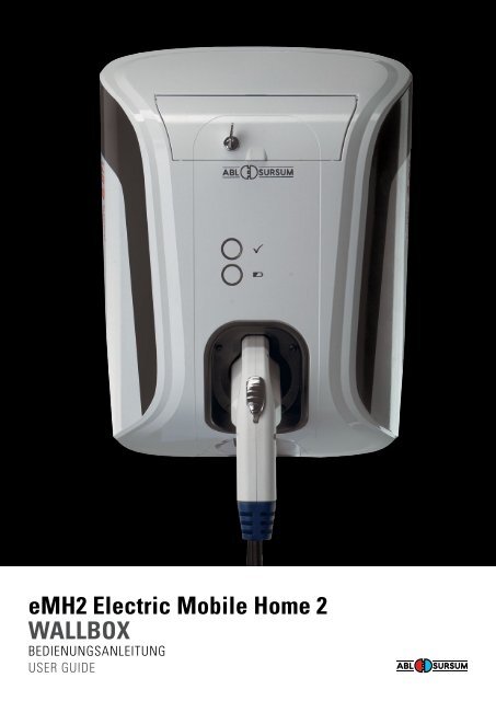
eMH2 <strong>Electric</strong> <strong>Mobile</strong> <strong>Home</strong> 2<br />
<strong>Wallbox</strong><br />
BEDIENUNGSANLEITUNG<br />
USER GUIDE
2<br />
eMH2 ladEbox INHALT<br />
CoNTENTS<br />
1 Einleitung 4<br />
2 Sicherheitshinweise 4<br />
2.1 Bedeutung der Sicherheitshinweise 4<br />
2.2 Allgemeine Sicherheitshinweise 4<br />
3 Allgemeine Kurzbeschreibung 5<br />
3.1 Anzeigen und Bedienelemente 5<br />
4 Komponenten 5<br />
5 Wandmontage 6<br />
5.1 Öffnen der Ladebox 6<br />
5.2 Wandmontage 6<br />
5.3 Elektrischer Anschluss und Inbetriebnahme 7<br />
6 Funktion 7<br />
6.1 Warnhinweise und Bedienung 7<br />
7 Bedienung 8<br />
7.1 Entnehmen des Ladesteckers aus der Ladebox 8<br />
7.2 Ladevorgang 8<br />
Varianten mit integriertem Ladekabel und Stecker 8<br />
Varianten mit eingebauter Ladedose; Ladekabel extern 8<br />
7.3 Ablauf normaler Ladevorgang 9<br />
8 Betriebsstörungen 10<br />
9 Pflege und Wartung 11<br />
10 Technische Daten 11<br />
10.1 Umgebungsbedingungen 11<br />
11 Konformitätserklärung 11<br />
English operating Manual 12
EINLEITUNG<br />
Ladebox<br />
1 Einleitung<br />
Diese Bedienungsanleitung enthält wichtige Hinweise zum Anschließen<br />
und zum sicheren Betrieb des Gerätes. Lesen und<br />
befolgen Sie unbedingt die angegebenen Sicherheitshinweise.<br />
Alle Sicherheitsbestimmungen sollten auch an andere Benutzer<br />
weitergegeben werden.<br />
2 Sicherheitshinweise<br />
2.1 bedeutung der Sicherheitshinweise<br />
GEFaHR!<br />
Die Nichtbeachtung dieses Zeichens kann zur Gefährdung von<br />
Leib und Leben führen.<br />
aCHTUNG!<br />
Die Nichtbeachtung dieses Zeichens kann zu Schäden am Gerät<br />
oder an angeschlossenen Verbrauchern führen.<br />
Dieses Zeichen weist auf Empfehlungen oder Besonderheiten hin.<br />
2.2 allgemeine Sicherheitshinweise<br />
Das Gerät ist nach dem Stand der Technik und den anerkannten<br />
sicherheitstechnischen Regeln gebaut. Dennoch können Personen<br />
verletzt oder kann das Gerät beschädigt werden, wenn die<br />
Sicherheitshinweise in dieser Bedienungsanleitung nicht beachtet<br />
werden. Das Gerät nur in technisch einwandfreiem Zustand be<br />
nutzen. Störungen, die die Sicherheit von Personen oder des Geräts<br />
beeinträchtigen, sofort von Fachpersonal beheben lassen. Fach<br />
personal im Sinne dieser Anleitung ist eine unterwiesene Fachkraft<br />
(nach BGV A3, DIN VDE 0105100 und DIN VDE 100010 oder der<br />
jeweils gültigen Ländernormen).<br />
GEFaHR!<br />
· Die elektrische Anlage entspricht den geltenden Richtlinien<br />
und Normen<br />
· Keine Manipulationen an elektrischer Anlage vornehmen.<br />
· Keine Veränderungen am Gerät vornehmen.<br />
· Elektrischen Anschluss nur von dafür ausgebildetem Fachpersonal<br />
gemäß Bedienungsanleitung durchführen lassen.<br />
· Gerät nicht mit defekten Leitungen oder fehlerhaftem Anschluss<br />
in Betrieb nehmen.<br />
· Keine Wartungsarbeiten am Gerät durchführen, wenn Spannung<br />
anliegt.<br />
· Elektrische Anschlüsse sachgemäß durchführen.<br />
· Richtige elektrische Absicherung sicherstellen.<br />
aCHTUNG!<br />
· Die Ladebox ist ausschließlich für den Anschluss an eine 230 V<br />
oder 230 / 400 V Spannungsversorgung vorgesehen, die<br />
Versorgungsleitungen können unter oder auf Putz verlegt werden.<br />
Der Kabeleintritt in der Rückschale ist bevorzugt unten.<br />
Vor der Inbetriebnahme, dem befestigen oder dem Öffnen<br />
der ladebox Sicherheitshinweise lesen und beachten.<br />
3
ALLGEMEINE KURZBESCHREIBUNG / KoMPoNENTEN<br />
Ladebox<br />
3 allgemeine Kurzbeschreibung<br />
Die Ladebox ermöglicht sicheres und bequemes Laden von Elektrofahrzeugen<br />
gemäß IEC 61851, Lademodus 3. In diesem Lademodus<br />
stellt die Ladebox sicher, dass eine SpannungsAufschaltung auf<br />
das Ladekabel erst dann erfolgt, wenn das Fahrzeug korrekt angeschlossen<br />
ist und die Maximalstromstärken angeglichen wurden.<br />
Durch in die Ladebox eingebaute Fehlerstrom und Leitungsschutzschalter<br />
wird weitere Sicherheit gewährleistet.<br />
3.1 anzeigen und bedienelemente<br />
Die Anzeige des aktuellen Leistungszustands der Ladebox erfolgt<br />
mittels zweier leuchtender Ringe (a und b) oder bei Geräten mit<br />
ECoMode mittels dreier farbig beleuchteter Ringe (a, b und c). Bei<br />
der Geräteausführung mit ECoMode ist zusätzlich ein Taster (d)<br />
vorhanden, um wahlweise die ECoFunktion zu oder abzuschalten.<br />
a)<br />
4<br />
<br />
· zeigt die Betriebsbereitschaft der Ladestation an<br />
· blinkt alle 5 sec. kurz: betriebsbereit<br />
· leuchtet nicht: nicht betriebsbereit oder Ladevorgang aktiv<br />
b) <br />
· zeigt den Ladevorgang an<br />
· leuchtet dauerhaft: Ladevorgang aktiv<br />
· blinkt: Ladung fahrzeugseitig beendet<br />
a)<br />
b)<br />
4 Komponenten<br />
Zum Umfang der Ladebox gehören:<br />
a) Basisstation mit fest verbundenem Ladestecker<br />
oder Ladesteckdose<br />
b) Montage und Bedienungsanleitung<br />
c) Bohrschablone
WANDMoNTAGE<br />
Ladebox<br />
5 Wandmontage<br />
5.1 Öffnen der ladebox<br />
Zur Montage des Gerätes muss das Gehäuse geöffnet werden.<br />
Hierzu ist der mit 4 Schrauben fixierte Steckereinsatz oder<br />
Steckdoseneinsatz zu demontieren.<br />
Steckereinsatz<br />
Dann die Frontabdeckung im Einsatzausschnitt fassen, aufkippen<br />
und, wie in der Abbildung gezeigt vom Rückteil des Gehäuses<br />
nach oben abnehmen.<br />
aCHTUNG:<br />
Die LED für die Leuchtringe sind nach der Montage des Rückteils<br />
in der Frontabdeckung zu fixieren. Kennzeichnung beachten.<br />
5.2 Wandmontage<br />
Die Bohrungen zur Befestigung und für das Zuleitungskabel sind<br />
nach Kenntnis der Befestigungssituation vom Fachpersonal zu<br />
bohren, hierfür sind Zentrierungen vorgesehen. Insbesondere im<br />
unteren Bereich, dem Austritt des Ladekabels, ist für sicheren Halt<br />
der Rückschale zu sorgen, da hier die Zugkräfte des Ladekabels<br />
aufgenommen werden. Die rot gekennzeichneten Befestigungspunkte<br />
sind bevorzugt zu verwenden.<br />
Zur Erleichterung der Montage ist dieser Anleitung eine Bohrschablone<br />
beigefügt.<br />
aCHTUNG:<br />
Bei der Befestigung des Rückteils ist darauf zu achten, dass die<br />
Schutzklasse II erhalten bleibt.<br />
<br />
5
WANDMoNTAGE / FUNKTIoN<br />
Ladebox<br />
5.3 Elektrischer anschluss und Inbetriebnahme<br />
Das Anschluss der elektrischen Zuleitung erfolgt je nach<br />
Ausführung an den mit L1, L2, L3, und N gekennzeichneten<br />
Leitungen, die in WagoKlemmen fixiert sind.<br />
<br />
Die Inbetriebnahme darf ausschließlich durch eine unterwiesene<br />
Fachkraft vorgenommen werden. Die DIN VDE 0105100 und<br />
DIN VDE 100010 oder die jeweils gültigen Ländernormen sind<br />
zu beachten.<br />
Vor der Inbetriebnahme, der Wandmontage oder dem Öffnen<br />
der Ladebox die Sicherheitshinweise lesen und beachten.<br />
6<br />
Die Kabelzuführung<br />
kann an den mit Zentrierungen<br />
versehenen<br />
Stellen einmal oben<br />
oder unten erfolgen.<br />
6 Funktion<br />
6.1 Warnhinweise und bedienung<br />
Die auf dem Gehäuse der Ladebox (siehe Warnhinweise in der<br />
Steckeraufnahme und Typenschild auf der Rückseite) angebrachten<br />
Symbole haben die folgenden Bedeutungen.<br />
<br />
<br />
<br />
<br />
<br />
Zugehörige Informationen sind der Bedienungsanleitung<br />
zu entnehmen<br />
Vorsicht, gefährliche elektrische Spannungen<br />
elektrische Schutzklasse II, d.h. es besteht eine verstärkte<br />
Isolierung zwischen Netzstromkreis und Ausgangsspannung<br />
siehe Bedienungsanleitung<br />
geprüfte CEKonformität<br />
Schutzklasse des Gerätes (geschützt gegen allseitiges<br />
Spritzwasser)<br />
Typenschild seitlich innen<br />
Aufkleber „Warnhinweise“<br />
auf der Innenseite
BEDIENUNG<br />
Ladebox<br />
7 bedienung<br />
Ist die Ladebox fachgerecht an die Stromversorgung angeschlossen,<br />
erfolgt der Beginn des Ladevorgangs mit dem Anschließen des<br />
Ladesteckers in die fahrzeug oder geräteseitige Ladesteckdose.<br />
Der Ladezyklus startet automatisch (siehe Ladevorgang).<br />
Eine Unterbrechung oder Beendigung des Ladevorganges erfolgt<br />
durch Ausstecken des Steckers auf der Fahrzeugseite.<br />
7.1 Entnehmen des ladesteckers aus der ladebox<br />
Ladestecker des Typ I können entnommen werden, indem bei<br />
gedrückt gehaltener Taste der Stecker in der angegeben Richtung<br />
entnommen wird.<br />
Ladestecker des Typ II werden entnommen indem man den Stecker<br />
in der gezeigten Richtung anhebt und dann aus der Halterung<br />
herausnimmt.<br />
7.2 ladevorgang<br />
Varianten mit integriertem ladekabel und Stecker<br />
· Stecker aus der Ladestation entnehmen<br />
· Stecker in Fahrzeugsteckdose einstecken<br />
Ladevorgang startet automatisch<br />
· Stecker vom Fahrzeug trennen und in der Ladestation ablegen<br />
Varianten mit eingebauter ladedose; ladekabel extern<br />
· Ladekabel in FahrzeugSteckdose und Ladestation stecken<br />
· Ladekabel wird in der Ladedose verriegelt<br />
Ladevorgang startet automatisch<br />
· Ladekabel vom Fahrzeug trennen<br />
Ladedose entriegelt automatisch<br />
· Ladekabel von der Ladestation trennen<br />
7
BEDIENUNG<br />
Ladebox<br />
7.3 ablauf normaler ladevorgang<br />
Der Ablauf des Ladevorgangs entspricht IEC 618511 Mode 3<br />
Zustand anzeige<br />
Stand by LED Ring blinkt<br />
<br />
LED Ring aus <br />
Elektrofahrzeug erkannt LED Ring an<br />
<br />
LED Ring aus <br />
Elektrofahrzeug Ladung LED Ring aus<br />
<br />
LED Ring an <br />
Ladung fahrzeugseitig beendet LED Ring aus<br />
<br />
LED Ring blinkt <br />
Stand by LED Ring blinkt<br />
<br />
LED Ring aus <br />
8
BETRIEBSSTÖRUNGEN<br />
Ladebox<br />
8 betriebsstörungen<br />
Bei Ausfall durch automatische Stromunterbrechung ist die<br />
unten dargestellte Klappe an der GehäuseVorderfront zu öffnen<br />
und der ausgelöste Schutzschalter durch Betätigen des Hebels<br />
wieder in seine Arbeitsstellung zu versetzen.<br />
Sollte diese Maßnahme nicht helfen und der Fehlerstromschutzschalter<br />
löst erneut aus so liegt möglicherweise ein Defekt vor,<br />
der nur von Fachpersonal behoben werden kann.<br />
Es ist zu beachten, dass die Gewährleitung bei unsachgemäß<br />
ausgeführter Reparatur erlischt und <strong>ABL</strong><strong>Sursum</strong> nicht für die<br />
dadurch entstandenen Folgeschäden haftet.<br />
Störung Mögliche Ursache abhilfe<br />
Ladevorgang startet nicht obwohl<br />
LED Ring blinkt<br />
<br />
Ladevorgang startet nicht,<br />
LED Ring leuchtet nicht<br />
<br />
Keine LED Anzeige · LED defekt<br />
LED Ring<br />
und<br />
LED Ring <br />
blinken abwechselnd<br />
<br />
· Ladekabel am Fahrzeug oder an der<br />
Ladebox nicht korrekt eingesteckt<br />
· FI Schutzschalter der Ladebox<br />
hat ausgelöst<br />
· Vorgelagerte Sicherung in der<br />
Hausverteilung ausgelöst<br />
· Leitung zur LED fehlerhaft<br />
· Stecker am Fahrzeug und ggf an der<br />
Ladebox auf korrekten Sitz prüfen<br />
(ausstecken, wieder anstecken)<br />
· Stecker am Fahrzeug abstecken, Klappe<br />
der Ladebox öffnen, FISchutzschalter<br />
rückstellen; Stecker wieder einstecken<br />
· Sicherungen der vorgelagerten<br />
Spannungsversorgung (in der Regel<br />
am Hausanschluss) überprüfen<br />
· Kundendienst informieren<br />
· Kundendienst informieren<br />
Fehlerfall Stecker vom Fahrzeug trennen und Laden<br />
wiederholen. Flls das Problem weiterhin<br />
besteht, den Kundendienst informieren.<br />
9
PFLEGE UND WARTUNG<br />
Ladebox<br />
9 Pflege und Wartung<br />
Die Ladebox kann mit einem trockenen Tuch gereinigt werden.<br />
Scharfe Reinigungsmittel könnten zum Eintrüben von Anzeigen<br />
(LEDAnzeige) führen.<br />
Die unter der Deckklappe eingebauten Fehlerstrom und Leitungsschutzschalter<br />
sind halbjährlich auf ihre Funktionsfähigkeit hin<br />
zu überprüfen. Hierzu ist die neben den Schaltern sichtbare Prüf <br />
taste zu betätigen, der Schalter fällt dann automatisch auf „Aus“.<br />
Per Hand ist er dann wieder in Arbeitsstellung zu bringen.<br />
Das eingebaute Ladekabel sollte regelmäßig auf Schadstellen<br />
oder Beschädigungen überprüft werden.<br />
Darüber hinaus gelten die jeweiligen gesetzlichen Bestimmungen<br />
für den Betrieb von elektrischen Geräten.<br />
10 Technische daten<br />
10.1 Umgebungsbedingungen<br />
Umgebungstemperatur (Lagerung) 30°C … 40°C<br />
Umgebungstemperatur (Betrieb) 25°C … 40°C<br />
Luftfeuchtigkeit 10% … 95% rH<br />
(nicht kondensierend)<br />
230 V oder 230 / 400VAC<br />
11 Konfirmitätserklärung<br />
Hiermit bestätigt die Firma <strong>ABL</strong> SURSUM Bayerische Elektrozubehör<br />
GmbH & Co. KG, als Hersteller der Ladebox, die Einhaltung der<br />
folgenden Richtlinien:<br />
CE Konformität 2006 / 95 / EG und 2004 / 108 / EG<br />
IEC 618511 2nd Edition (Grundnorm)<br />
IEC 6185122 2nd Edition (Gerätenorm)<br />
10
1 Ein / aus-Schalter<br />
Das unter der Abdeckklappe befindliche Bedienelement ermöglicht<br />
das Beenden und WiederStarten des Ladevorgangs durch Betätigung<br />
des auf der rechten Seite des Bedienfensters befindlichen<br />
Schalters (Stellung „0 oFF“ bzw. „I oN“). Der Ladevorgang kann<br />
nur in der Schalterstellung „I oN“ gestartet werden.<br />
2 abschließbare abdeckklappe der Sicherungsautomaten<br />
Zur Vermeidung von unbefugtem Manipulieren der Ladestation<br />
kann der Zugang zu den Bedienelemente abgeschlossen werden<br />
(nicht vandalensicher!). Dem Gerät sind zwei Schlüssel beigelegt. Bei<br />
Verlust wenden Sie sich bitte an Ihren zuständigen ServiceBetrieb.<br />
3 bohrschablone für Wandmontage<br />
Zeichnungsblatt 4 im Format DIN A2 ausgedruckt dient der<br />
Positionsfestlegung der Bohrungen für die Wandmontage<br />
des Gerätes. Die Befestigungsfläche muss eine Größe von<br />
mindestens 250 x 360 mm aufweisen!<br />
Download www.ablsursum.com<br />
<br />
<br />
<br />
11
INTRoDUCTIoN<br />
<strong>Wallbox</strong><br />
1 Introduction<br />
This operating manual is intended to provide users with important<br />
information on installing and operating the charging box.<br />
Please read and follow all the safety instructions. All users must<br />
be provided with information regarding health and safety.<br />
2 Safety Instructions<br />
2.1 Safety symbols used in this manual<br />
daNGER!<br />
Indicates a hazardous situation that, if not avoided, may result in<br />
serious injury or death.<br />
WaRNING!<br />
Indicates a hazardous situation that, if not avoided, may result in<br />
damage to the device or connected consumers.<br />
This symbol indicates recommendations or special features.<br />
2.2 General safety instructions<br />
The charging box is manufactured using stateoftheart techniques<br />
and in accordance with approved safety regulations. Nonetheless,<br />
always follow the safety instructions in this operating manual to<br />
prevent personal injuries and damage to the charging box. Make<br />
sure the charging box is in efficient working order before use. Ensure<br />
that any faults which affect personal and operational safety are<br />
eliminated immediately by a qualified member of staff. This manual<br />
defines qualified service personnel as fully trained specialists (in<br />
accordance with BGV A3, DIN VDE 0105100 and DIN VDE 100010<br />
or relevant national standards).<br />
12<br />
daNGER!<br />
· The electrical system corresponds to valid regulations and<br />
standards.<br />
· Do not manipulate the electrical system.<br />
· Do not modify the charging box.<br />
· Ensure electrical connection of the charging box is carried out<br />
by trained and qualified staff in accordance with instructions.<br />
· Never operate the charging box with damaged wires or cables<br />
or faulty connections.<br />
· Never carry out maintenance tasks if the charging box is still<br />
connected to sources of supply.<br />
· Ensure all electrical connections are correct.<br />
· Ensure the electrical safety devices are working properly and<br />
are correct.<br />
WaRNING!<br />
· The charging box is only intended for connection to a 230V or<br />
230/400V power supply; the supply lines can be flush or surface<br />
mounted. The preferred cable entry point is at the bottom of<br />
the rear unit.<br />
Please read and follow the safety instructions prior to<br />
commissioning, fixing or opening the charging box.
GENERAL SHoRT DESCRIPTIoN /CoMPoNENTS<br />
<strong>Wallbox</strong><br />
3 General Short description<br />
The charging box enables safe and convenient charging of electric<br />
vehicles in accordance with IEC 61851, charging mode 3. In this<br />
charging mode the charging box ensures that power is only switched<br />
on, if the vehicle has been connected correctly and current<br />
limits are set. Residual current circuit breakers and circuit breakers<br />
ensure further protection.<br />
3.1 display and operating elements<br />
The current power status of the charging box is displayed via two<br />
illuminated rings (a and b) and for charging boxes with ECo mode<br />
via three colour illuminated rings (a, b and c). An additional button<br />
(d) is provided for ECo mode charging boxes in order to switch the<br />
ECo function on or off.<br />
a)<br />
<br />
· displays the operational availability of the charging station<br />
· flashes briefly every 5 seconds: ready for operation<br />
· not illuminated: not ready for operation or charging cycle active<br />
b) <br />
· displays the charging cycle<br />
· illuminates permanently: charging cycle active<br />
· flashes: charging completed signalled by the vehicle<br />
a)<br />
b)<br />
4 Components<br />
The charging box includes:<br />
a) Base station with permanently connected charging<br />
plug or charging socket<br />
b) Installation and operating instructions<br />
13
WALL INSTALLATIoN<br />
<strong>Wallbox</strong><br />
5 Wall installation<br />
5.1 opening the charging box<br />
open the housing to install the charging box correctly.<br />
Disassemble the 4 screws of the plug insert or the socket insert.<br />
Plug insert<br />
Subsequently use the insert recess to lift up and remove the front<br />
cover from the rear unit as shown.<br />
CaUTIoN:<br />
Fix the LEDs for the illuminated rings in the front cover after<br />
installing the rear unit. Pay attention to the labelling.<br />
14<br />
5.2 Wall installation<br />
Specialist staff familiar with the attachment situation should use<br />
the provided centring guides to drill the holes for attachment and<br />
the feed cable. Make sure the lower part of the rear unit is secured<br />
sufficiently, where the charging cable exists the box, as this section<br />
absorbs the forces created by cable. Preferably use the red attachment<br />
points.<br />
A drilling template supplied with this manual facilitates installation.<br />
CaUTIoN:<br />
Ensure that protection class II is still provided after installing the<br />
rear unit.<br />
WALL INSTALLATIoN / FUNCTIoN<br />
<strong>Wallbox</strong><br />
5.3 <strong>Electric</strong>al connection and comissioning<br />
Depending on the actual version, connect the power supply to the<br />
cables marked L1, L2, L3 and N fixed in Wago terminals.<br />
<br />
The cable can be routed<br />
at the points with the<br />
centring either from the<br />
top or the bottom.<br />
Comissioning should only be carried out by authorized and fully<br />
qualified staff. Always pay attention to relevant national standards.<br />
Please read and follow the safety instructions prior to<br />
commissioning, wall installation or opening the charging box.<br />
6 Function<br />
6.1 Warnings and operation<br />
The symbols specified on the housing of the charging box (see warning<br />
information in the plug holder and the type plate on the rear)<br />
have the following meanings.<br />
<br />
<br />
<br />
<br />
<br />
Refer to the operating manual for respective information<br />
Caution high voltages<br />
<strong>Electric</strong>al protection class II, i.e. there is reinforced<br />
insulation between the main supply circuit and the<br />
output voltage<br />
Refer to the operating manual<br />
Tested CE conformity<br />
Ingress protection of the charging box (protected<br />
against water spray from any direction)<br />
Type plate inside the box<br />
”Warning sticker“ on<br />
the inside<br />
15
oPERATIoN<br />
<strong>Wallbox</strong><br />
7 operation<br />
once the charging box has been connected to the power supply,<br />
start the charging cycle by inserting the charging plug into the<br />
charging socket at the vehicle or the charging box.<br />
The charging cycle starts automatically (see charging cycle).<br />
Interrupt or stop the charging cycle by disconnecting the plug<br />
from the vehicle.<br />
7.1 Removing the charging plug from the charging box<br />
Remove a IEC Type I charging plug by pressing the button and<br />
extracting the plug in the displayed direction.<br />
Remove a IEC Type II charging plug by lifting the plug as displayed<br />
and then extracting it from the holder.<br />
16<br />
7.2 Charging cycle<br />
Versions with integrated charging cable and plug<br />
· Remove the plug from the charging station<br />
· Insert the plug into the vehicle socket<br />
Charging cycle starts automatically<br />
· Disconnect the plug from the vehicle and place it back<br />
in the charging station<br />
Versions with integrated charging socket;<br />
external charging cable<br />
· Insert the charging cable in the vehicle <br />
socket and in the charging station<br />
· The charging cable is locked in the charging socket<br />
Charging cycle starts automatically<br />
· Disconnect the charging cable from the vehicle<br />
Charging socket unlocks automatically<br />
· Disconnect the charging cable from the charging station
oPERATIoN<br />
<strong>Wallbox</strong><br />
7.3 Normal charging cycle<br />
The charging cycle corresponds to IEC 618511 Mode 3<br />
Status display<br />
Stand by LED flashes<br />
<br />
LED off <br />
<strong>Electric</strong> vehicle detected LED on<br />
<br />
LED off <br />
<strong>Electric</strong> vehicle charging LED off<br />
<br />
LED on <br />
Charging completed at the vehicle LED off<br />
<br />
LED flashes <br />
Stand by LED flashes<br />
<br />
LED off <br />
1 Service procider switch<br />
Allows the recharge process to be interrupted by turning the switch<br />
located on the right hand side of the control panel to the „0 oFF“<br />
position. To start the recharge process, the switch must be in the<br />
„1 oN“ position. Charging (normal & eco) can be started only in the<br />
position „1 oN“.<br />
2 lockable circuit breaker cover<br />
In order to prevent tampering, the charging station has a lockable<br />
controls cover (not vandalismproof). The wallbox is supplied with<br />
two keys. If lost, please contact your service provider.<br />
3 drilling template for wall mounting<br />
Schematic drawing No. 4 printed in a size DIN A2 sheet serves<br />
as a template for determining the positions of the holes for wall<br />
mounting. The mounting surface must measure at least 250x360<br />
mm (10"x15")! Download: www.ablsursum.com<br />
<br />
<br />
<br />
17
TRoUBLESHooTING<br />
<strong>Wallbox</strong><br />
8 Troubleshooting<br />
If an automatic power failure occurs, open the front cover shown<br />
below and use the lever to reset the tripped circuit breaker.<br />
If this is unsuccessful and the residual current circuit breaker trips<br />
again, there is probably a fault that can only be eliminated by<br />
trained and qualified personnel.<br />
Please note that the warranty will not apply if unauthorized repairs<br />
are carried out. <strong>ABL</strong>SURSUM shall not be liable for any consequential<br />
damages or losses.<br />
Fault Possible cause Remedy<br />
Charging cycle does not start even<br />
though the LED is flashing<br />
<br />
Charging cycle does not start even<br />
though the LED is not illuminated<br />
<br />
No LED display · LED defective<br />
LED<br />
and<br />
LED <br />
flash alternately<br />
18<br />
<br />
Charging cable not inserted correctly<br />
at the vehicle or at the charging box<br />
· Residual current circuit breaker of<br />
the charging box has tripped<br />
· Upstream fuse in the house fuse box<br />
has blown<br />
· LED wire faulty<br />
Check secure connection of the plug at the<br />
vehicle and, if necessary, at the charging box<br />
(disconnect, reconnect the plug)<br />
· Disconnect the plug at the vehicle, open<br />
the cover of the charging box, reset the<br />
residual circuit breaker; reconnect the plug<br />
· Check the fuses of the upstream power<br />
supply (usually in the house fuse box)<br />
· Contact the Customer Service Department<br />
· Contact the Customer Service Department<br />
Fault Disconnect the plug from the vehicle and<br />
repeat charging. If the problem occurs again,<br />
contact the Customer Service Department
CARE AND MAINTENANCE<br />
<strong>Wallbox</strong><br />
9 Care and Maintenance<br />
Clean the charging box with dry cloth. Aggressive cleaning agents<br />
may damage the finish of displays.<br />
Check the correct functioning of the residual current circuit breakers<br />
and circuit breakers integrated underneath the cover every six<br />
month. Press the test button next to the circuit breakers, which are<br />
then automatically set to ”oFF“. Manually reset it to the operating<br />
position.<br />
Regularly check cables for any signs of fraying, breakage or damage.<br />
Furthermore, the relevant statutory regulations apply for the<br />
operation of electrical devices.<br />
10 Technical data<br />
10.1 ambient conditions<br />
Ambient temperature (storage) 30°C … 40°C<br />
Ambient temperature (operation) 25°C … 40°C<br />
Humidity 10% … 95% rH<br />
(noncondensing)<br />
230 V or 230 / 400VAC<br />
11 declaration of Conformity<br />
<strong>ABL</strong> SURSUM Bayerische Elektrozubehör GmbH & Co. KG as<br />
manufacterer of the charging box hereby confirms adherence<br />
to the following regulations:<br />
CE conformity 2006/ 2006/95/EG und 2004/108/EG<br />
IEC 618511 2nd Edition (basic standard)<br />
IEC 6185122 2nd Edition (equipment standard)<br />
19
Seit über 90 Jahren die Kompetenz beim<br />
Verbinden und Sichern von Strom – weltweit<br />
Worldwide leadership in connecting<br />
and protecting power – for over 90 years<br />
Made in Germany<br />
abl SURSUM<br />
Bayerische Elektrozubehör GmbH & Co. KG<br />
Ottensooser Straße 22<br />
91207 Lauf / Pegnitz<br />
Postfach 10 02 47<br />
91192 Lauf / Pegnitz<br />
Telefon +49 (0) 9123 188-0 info@abl-sursum.com<br />
Telefax +49 (0) 9123 188-188 www.abl-sursum.com<br />
0301402 / 05.2012