LCD-Farbmonitore, VMC-17LCD-PW, VMC-23LCD-PW ... - Videor
LCD-Farbmonitore, VMC-17LCD-PW, VMC-23LCD-PW ... - Videor
LCD-Farbmonitore, VMC-17LCD-PW, VMC-23LCD-PW ... - Videor

Erfolgreiche ePaper selbst erstellen
Machen Sie aus Ihren PDF Publikationen ein blätterbares Flipbook mit unserer einzigartigen Google optimierten e-Paper Software.
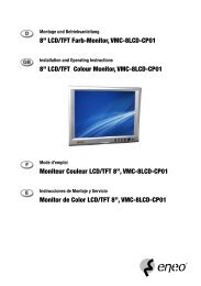
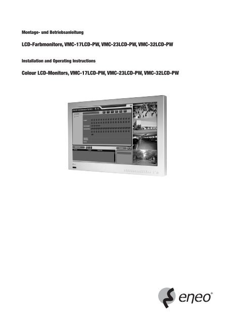
Montage- und Betriebsanleitung<br />
<strong>LCD</strong>-<strong>Farbmonitore</strong>, <strong>VMC</strong>-17<strong>LCD</strong>-<strong>PW</strong>, <strong>VMC</strong>-23<strong>LCD</strong>-<strong>PW</strong>, <strong>VMC</strong>-32<strong>LCD</strong>-<strong>PW</strong><br />
Installation and Operating Instructions<br />
Colour <strong>LCD</strong>-Monitors, <strong>VMC</strong>-17<strong>LCD</strong>-<strong>PW</strong>, <strong>VMC</strong>-23<strong>LCD</strong>-<strong>PW</strong>, <strong>VMC</strong>-32<strong>LCD</strong>-<strong>PW</strong><br />
1
Inhalt<br />
1. Sicherheitshinweise....................................................................................................................................................................................................................... 3<br />
2. Allgemeine Beschreibung............................................................................................................................................................................................................... 3<br />
3. Beschreibung des Monitors und der Bedienelemente ..................................................................................................................................................................... 4<br />
4. Multiplexer-Funktionen .................................................................................................................................................................................................................. 6<br />
5. VCR-, PC- und Component-Betrieb................................................................................................................................................................................................. 7<br />
6. Alarmmodus .................................................................................................................................................................................................................................. 8<br />
7. Einstellungen ................................................................................................................................................................................................................................. 8<br />
8. Programmierung über Bildschirmmenü.......................................................................................................................................................................................... 9<br />
9. Installation der PC-Software......................................................................................................................................................................................................... 26<br />
10. Fernbedienung............................................................................................................................................................................................................................. 29<br />
11. Spezifikationen ............................................................................................................................................................................................................................ 30<br />
12. Maßzeichnungen ......................................................................................................................................................................................................................... 59<br />
Contents<br />
1. Safety instructions ....................................................................................................................................................................................................................... 31<br />
2. General description...................................................................................................................................................................................................................... 31<br />
3. Description of the monitor and the controls.................................................................................................................................................................................. 32<br />
4. Multiplexer Functions................................................................................................................................................................................................................... 34<br />
5. VCR, PC and Component Mode..................................................................................................................................................................................................... 35<br />
6. Alarm Mode ................................................................................................................................................................................................................................. 36<br />
7. Setup Mode ................................................................................................................................................................................................................................. 36<br />
8. Installation of the PC software...................................................................................................................................................................................................... 37<br />
9. Programming Screens ................................................................................................................................................................................................................. 54<br />
10. Remote Control............................................................................................................................................................................................................................ 57<br />
11. Specifications .............................................................................................................................................................................................................................. 58<br />
12. Dimensional Drawings ................................................................................................................................................................................................................. 59<br />
Betriebsanleitung<br />
Installation and Operating Instructions<br />
Mode d’emploi<br />
⇒<br />
www.eneo-security.com/manuals<br />
2
1. Sicherheitshinweise<br />
• Bitte lesen Sie die Sicherheitshinweise und die Betriebsanleitung vor Anschluss und Inbetriebnahme des Geräts durch.<br />
• Bewahren Sie die Betriebsanleitung für spätere Bezugnahme an einem sicheren Ort auf.<br />
• Der Monitor erzeugt während des Betriebs zwar nur eine minimale Wärmeabgabe, aber diese Wärme muss dennoch aus dem Gerät abgeführt und kalte Luft<br />
zugeführt werden.<br />
• Um einen Wärmestau zu vermeiden, niemals die Lüftungsschlitze abdecken.<br />
• Um die Luftzirkulation zu garantieren, sicherstellen, dass das Gerät in einem ausreichenden Abstand von anderen Geräten und Wänden positioniert ist.<br />
Überhitzung reduziert die Lebensdauer des Geräts und kann in Extremfällen zu einem Brand führen.<br />
• Wenn es in geschlossenen Schränken betrieben wird, müssen Sie unbedingt sicherstellen, dass genügend freier Raum für die Belüftung vorhanden ist.<br />
• Wenn der Monitor aus einer kalten Umgebung in einen warmen Raum gebracht wird, lassen Sie ihn erst auf Raumtemperatur aufwärmen, bevor Sie ihn einschalten.<br />
• Schützen Sie das Gerät und die Anschlusskabel vor dem Eindringen von Wasser und Feuchtigkeit. Das Gerät niemals einschalten, wenn dennoch Feuchtigkeit eingedrungen<br />
ist. Lassen Sie es von einem Fachunternehmen prüfen. Feuchtigkeit kann das Gerät schwer beschädigen, und es besteht die Gefahr eines Stromschlags.<br />
• Das Gerät darf nur innerhalb des Temperaturbereichs von 0°C bis +40°C und bei einer Luftfeuchtigkeit von maximal 90% betrieben werden.<br />
• Den Monitor nicht direkter Sonneneinstrahlung aussetzen oder ihn neben ein Fenster stellen. Feuchtigkeit und direkte Sonneneinstrahlung können zu schweren<br />
Schäden führen.<br />
• Niemals irgendwelche metallischen oder anderen Gegenstände in die Belüftungsöffnungen stecken. Dies kann zu bleibenden Schäden am Gerät führen.<br />
• Keinen direkten Druck auf den <strong>LCD</strong>-Bildschirm des Monitors ausüben. Übermäßiger Druck kann zu bleibenden Schäden der Anzeige führen.<br />
• Trennen Sie den Monitor vom Stromnetz, bevor Sie ihn reinigen oder wenn er für längere Zeit nicht benutzt wird. Niemals die Netzspannung nur am Kabel trennen,<br />
immer den Netzstecker aus der Steckdose ziehen.<br />
• Beim Verlegen des Anschlusskabels sicherstellen, dass es nicht unter Zug steht oder geknickt oder beschädigt wird.<br />
• Das Gerät darf nur von autorisiertem Fachpersonal geöffnet werden.<br />
• Nur Originalzubehör und Originalersatzteile verwenden.<br />
• Die Person, die dieses System einsetzt, ist verantwortlich für die Kenntnisnahme und Einhaltung der geltenden lokalen, bundesstaatlichen und nationalen<br />
Bestimmungen und Verordnungen bezüglich Aufzeichnung und Überwachung von Audiosignalen.<br />
2. Allgemeine Beschreibung<br />
Die <strong>VMC</strong>-17<strong>LCD</strong>-<strong>PW</strong> / 23<strong>LCD</strong>-<strong>PW</strong> und <strong>VMC</strong>-32<strong>LCD</strong>-<strong>PW</strong> sind 4-Kanal <strong>LCD</strong>-Farbmonitor für Überwachungszwecke mit einem eingebauten Multiplex-Prozessor für die<br />
gleichzeitige Überwachung von bis zu vier verschiedenen Kamerastandorten und mit einer eingebauten hochauflösenden Kamera.<br />
Dieser Farbmultiplex-Prozessor bietet ein benutzerfreundliches, programmierbares OSD-Menü.<br />
Die Kameras können sequenziell bei Alarm, als Vollbild oder Quad (mit vier Bildern) auf einem Bildschirm angezeigt werden.<br />
• TFT-<strong>LCD</strong> MUX-Farbmonitor<br />
• TFT-<strong>LCD</strong> Farbmonitor mit großer Helligkeit und hohem Kontrast<br />
• Vollbildanzeige<br />
• Hochauflösende Vierfachanzeige<br />
• Doppelfensteranzeige - Haupt- und Nebenfenster<br />
• Bewegungserkennung und Speicherfunktion<br />
• Bilderfassung und Abspielfunktion<br />
• Möglichkeit, den Bildschirm einzufrieren<br />
• Alarmeingang und -ausgang - Ruhekontakt und Schaltkontakt<br />
• Alarm für Videosignalverlust und Bewegungserkennung<br />
• VCR-Eingänge und -ausgänge<br />
• Benutzerfreundliches Programmiermenü - On Screen Display (OSD)<br />
• Key-Lock / Menü-Passwortfunktion<br />
• Zählfunktion für Alarme / Videosignalverlust<br />
• Zeit-und Datumsstempel<br />
Lieferumfang<br />
1x Netzkabel<br />
1x VGA-Kabel<br />
1x Netzteil<br />
1x Montage- und Betriebsanleitung<br />
1x Fernbedienung (inkl. Batterien)<br />
3
3. Beschreibung des Monitors und der Bedienelemente<br />
Front<br />
Nr. Funktion Beschreibung<br />
1 QUAD Drücken Sie die Taste QUAD, um die Vierfachanzeige zu aktivieren.<br />
2<br />
SEQ<br />
3 CAM1-CAM4<br />
4 MENU<br />
MENU<br />
5 AB/AUF<br />
6<br />
( / )<br />
LINKS/RECHTS<br />
( / )<br />
Die QUAD-Taste wird auch zur Anzeige von PC-Daten oder COMPONENT-Video verwendet.<br />
Die Sequenz ist QUAD, PC, COMPONENT, QUAD usw.<br />
Durch Drücken von SEQ wird die Sequenzanzeige gestartet.<br />
In der Vollbildanzeige wird durch Drücken dieser Taste die Sequenzierung der Vollbildanzeige (Cam1-Cam4) oder die benutzerdefinierte<br />
Sequenzierung gestartet.<br />
Wenn das Gerät in diesem Modus arbeitet, wird der Name (Titel) der Kamera des momentan angezeigten Bildes links oben auf dem<br />
Bildschirm angezeigt.<br />
Durch Drücken der Tasten CAM1-CAM4 wird das Bild von Kamera1-Kamera4 als Vollbild angezeigt.<br />
Durch Drücken der Taste MENU wird das Gerät in den Programmiermodus versetzt.<br />
Sie wird auch zum Aufrufen der vorherigen Einstellung oder zum Verlassen des OSD-Systems verwendet.<br />
Dadurch können Kameraoptionen, Alarmoptionen, Bildparameter, Konfiguration und andere Elemente eingestellt werden.<br />
Mit den AUF- und AB-Tasten bewegen Sie sich um OSD-Menü nach oben oder unten.<br />
Ist das OSD-Menü nicht aktiv, werden sie zur Lautstärkeeinstellung verwendet.<br />
Mit den LINKS- und RECHTS-Tasten wird der Wert des ausgewählten Elements verringert bzw. vergrößert.<br />
Bei nicht aktivem OSD-Menü wird mit der LINKS-Taste der Ton ausgeschaltet.<br />
Die RECHTS-Taste wird zur Anzeige der Lautstärke verwendet, wenn das OSD-Menü nicht aktiv ist.<br />
7 FREEZE Diese Taste wird zum Einfrieren des Bildes verwendet.<br />
Zum Verlassen des Einfrierens; die Taste nochmals drücken.<br />
(Diese Funktion ist nicht wirksam, wenn auf der Hauptanzeige das PC-oder S-Video-Signal dargestellt wird.)<br />
8 CAPTURE Mit der CAPTURE-Taste wird das aktuelle Bild gespeichert.<br />
9<br />
10<br />
VCR<br />
ZOOM<br />
11 POP<br />
12<br />
<strong>PW</strong>R<br />
Es werden bis zu 60 Felder unterstützt.<br />
Diese Funktion kann nur ausgeführt werden, wenn im Hauptfenster die Vollbildanzeige aktiviert ist (CA1-CA4).<br />
Mit dieser Taste wird das Videosignal ausgewählt, das über die Anschlüsse VCR IN oder S-VIDEO eingespeist wird.<br />
Der verfügbare Video-Modus kann durch wiederholtes Drücken der VCR-Taste ausgewählt werden.<br />
Das Echtzeit-Videosignal, das an den VCR IN/S-VIDEO-Anschluss angeschlossen ist, wird durch Auswahl des Modus Video/S-Video<br />
angezeigt, und das Multiplex-Video wird in QUAD-Manier durch Auswahl des PB MODE angezeigt.<br />
Zum Zoomen der aktuellen Bildschirmanzeige.<br />
Der Zoom-Bereich kann mit den Tasten AUF/AB/LINKS/RECHTS verschoben werden.<br />
Für normale Bildgröße nochmal die ZOOM-Taste drücken.<br />
Diese Funktion wird im Modus QUAD/PC/COMPONENT VIDEO nicht unterstützt.<br />
Drücken Sie die POP-Taste, um das POP-Fenster anzuzeigen.<br />
Mit der <strong>PW</strong>R-Taste wird der Monitor eingeschaltet. – Die <strong>PW</strong>R-LED leuchtet auf.<br />
Durch nochmaliges Drücken der <strong>PW</strong>R-Taste wird der Monitor wieder ausgeschaltet. – Die <strong>PW</strong>R-LED verlischt.<br />
Grün - Normalbetrieb<br />
Gelb - Stromsparmodus<br />
1<br />
2<br />
4<br />
3 4<br />
5<br />
6<br />
7<br />
9<br />
11<br />
8 10 12
Rückseite<br />
<strong>VMC</strong>-17<strong>LCD</strong>-<strong>PW</strong><br />
<strong>VMC</strong>-23<strong>LCD</strong>-<strong>PW</strong><br />
<strong>VMC</strong>-32<strong>LCD</strong>-<strong>PW</strong><br />
A B C D E F G H I<br />
K<br />
K<br />
A B C D E F G J H I<br />
K<br />
B C D E F G J H I<br />
5<br />
A
Nr. Beschriftung Funktion<br />
M AC IN Netzanschlussbuchse Netzkabel an den Anschluss AC IN an der Rückseite des Monitors anschließen. (<strong>VMC</strong>-32<strong>LCD</strong>-<strong>PW</strong>)<br />
A DC IN Netzteilanschlussbuchse Netzteilstecker an den DC-Stromanschluss an der Rückseite des Monitors anschließen. (<strong>VMC</strong>-17<strong>LCD</strong>-<strong>PW</strong>, <strong>VMC</strong>-23<strong>LCD</strong>-<strong>PW</strong>)<br />
B<br />
CA1 - 4<br />
An die BNC-Anschlüsse, die mit CA1, CA2, CA3 und CA4 beschriftet sind, können vier Kameras angeschlossen werden.<br />
Es kann sowohl der linke als auch der rechte BNC-Anschluss als Eingang oder Ausgang verwendet werden.<br />
Die Anschlüsse haben selbstterminierende interne Schalter.<br />
C S-VIDEO S-VHS-Kabel an den Video-Ausgang von Kamera, VCR oder DVD anschließen.<br />
D<br />
E<br />
F<br />
G<br />
VCR IN/OUT<br />
MONITOR OUT<br />
SPOT OUT<br />
PC<br />
Der BNC VCR-Anschluss wird zum Anschließen eines VCR an den Monitor zu Aurnahmezwecken verwendet.<br />
Der Video-Ausgang kann auch das gemultiplexte oder das Vierfach-Bildsignal führen.<br />
Das BNC-Kabel an andere Monitore anschließen, wenn Sie dasselbe Hauptfenster auch auf anderen Monitoren anzeigen<br />
möchten.<br />
Der Monitor-Ausgang führt das letzte Kamerasignal des Bewegungsmelders, wenn das Hauptfenster in den QUAD-<br />
Modus geschaltet ist.<br />
(PC- und COMPONENT-Videoeingang werden nicht unerstützt.)<br />
SPOT OUT ist der zusätzliche Video-Ausgang.<br />
Er kann das Signal CA1, CA2, CA3, CA4 oder QUAD (REC OUTPUT) führen, außerdem unterstützt er den SEQUENCE-Modus.<br />
Den 15-poligen D-SUB-Stecker mit dem Videosignal des PCs an diesen Videoanschluss an der Rückseite des Monitors<br />
anschließen.<br />
H AUDIO RCA-Audiokabel an die Audio-Ausgänge von VCR oder DVD anschließen.<br />
I<br />
J<br />
ALARM IN / OUT<br />
TRIGGER INPUT<br />
COMPONENT*<br />
Alarmeingang an den Alarmeingangsanschluss anschließen, und den Alarmausgangsanschluss mit anderen Geräten<br />
verbinden, die eine Alarmeingangsfunktion unterstützen.<br />
Synchronisationsimpulse des VCR mit dem Trigger-Eingang des Monitors verbinden (nur <strong>VMC</strong>-32<strong>LCD</strong>-<strong>PW</strong>).<br />
Die COMPONENT-Videoquelle eines DVD- oder anderen Geräts, das einen COMPONENT-Video-Ausgang besitzt, mit dem<br />
RCA-Kabel (nicht mitgeliefert) anschließen.<br />
K SPEAKER Der Audio-Ausgang des VCR kann mit dem eingebauten Lautsprecher des Geräts abgehört werden.<br />
L MAIN POWER SWITCH Schalter für die Spannungsversorgung (nur <strong>VMC</strong>-32<strong>LCD</strong>-<strong>PW</strong>)<br />
4. Multiplexer-Funktionen<br />
Quad Display<br />
Durch Drücken der Taste QUAD wird eine Vierfachanzeige mit vier Kamerabildern angezeigt.<br />
Bei nicht installierten oder deaktivierten Kameras wird ein schwarzer Hintergrund angezeigt.<br />
Verwenden Sie die folgende Tabelle als Anleitung für die im QUAD-Modus möglichen Funktionen.<br />
Taste(n) Bedienvorgang<br />
QUAD (Hauptfenster) QUAD-Taste wiederholt drücken, bis die QUAD-Anzeige im Hauptfenster erscheint.<br />
Vollbild<br />
POP Drücken Sie die POP-Taste, um das Unterfenster anzuzeigen.<br />
POP: Vier vom Bewegungssensor erkannte Bilder<br />
Das zuletzt erkannte Kamerabild ist eine Live-Anzeige, aber die anderen sind eingefroren.<br />
Die Taste mit der gewünschten Kameranummer drücken, um die entsprechende Vollbildanzeige zu aktivieren.<br />
Die ausgewählte Kamera wird im Hauptfenster angezeigt.<br />
Taste(n) Bedienvorgang<br />
CA 1 - 4<br />
(Hauptfenster)<br />
Taste mit der gewünschten Kameranummer drücken, um die Hauptanzeige auf die Vollbildanzeige der Kamera zu schalten.<br />
POP Echtzeitanzeige von vier Kameras<br />
Sequenzanzeige<br />
Durch Drücken von SEQ wird die Sequenzanzeige der Kameras eingeschaltet.<br />
Der Kameratitel wird links oben auf dem Bildschirm angezeigt.<br />
Sind Kameras nicht installiert oder deaktiviert, werden sie in der Sequenz ausgelassen.<br />
Die Verweilzeit jeder Kamera kann im Sequenz-Einstellungsmenü individuell festgelegt werden.<br />
Taste(n) Bedienvorgang<br />
SEQ (Hauptfenster) SEQ drücken, um die Sequenzanzeige der Kameras zu starten.<br />
POP Echtzeitanzeige von vier Kameras<br />
Anzeige einfrieren<br />
Durch Drücken von FREEZE wird die Anzeige eingefroren.<br />
Im Freeze-Modus wird auf dem Bildschirm blinkend FREEZE angezeigt, und das Bild wird auf dem Bildschirm eingefroren, bis die FREEZE-Taste erneut gedrückt wird.<br />
Hinweis: In den Modi PC und COMPONENT ist die FREEZE-Funktion nicht verfügbar.<br />
6
5. VCR-, PC und Component-Betrieb<br />
Übersicht Mit dem VCR-Modus kann der Video-Playback des VCR angezeigt werden.<br />
S-Video Kabel mit dem S-Video-Signal an den S-Video-Anschluss anschließen.<br />
VCR-Taste drücken, bis der Modus S-Video ausgewählt ist.<br />
VCR-Playback Nach dem Drücken der PLAY-Taste des VCR wird durch Drücken der VCR-Taste das VCR-Playback angezeigt.<br />
Der Eingang VCR PLAYBACK kann ein zeitmultiplextes Videosignal von Kameras oder ein Echtzeit-Videosignal sein.<br />
Durch Wählen von QUAD PB MODE wird das zeitmultiplexte Videosignal der Kameras angezeigt und der Video-Modus auf Live-Video geschaltet.<br />
VCR-Ausgang Das Signal des VCR-Ausgangs wird in den Eingang des VCR geführt. Dieser Monitor unterstützt zwei VCR-Ausgangsmodi. Beim einen wird das<br />
feldgeschaltete Ausgangssignal von vier Kameras verwendet, und beim anderen das QUAD-Signal der Kameras. Das Feldschaltintervall kann im<br />
Einstellungsmenü eingestellt werden.<br />
Spot-Ausgang Der Spot-Ausgang ist der Zusatzausgang. Es kann sich um CA1, CA2, CA3, CA4 oder den VCR-Ausgang handeln. Die Auswahl des SPOT-Ausgangs<br />
wird im OSD-Einstellungsmenü eingestellt.<br />
PC-Betrieb Das VGA-Kabel mit dem PC, und dann mit dem Monitor verbinden.<br />
Video-Modus<br />
(Component)<br />
POP-Anzeige<br />
QUAD-Taste drücken, bis der PC MODE ausgewählt ist.<br />
Die Auflösung der Grafikkarte des PCs so einstellen, dass die Anzeigequalität optimal ist.<br />
Die empfohlene Auflösung für den Monitor ist 1024x768 bei 60Hz.<br />
Die Videoquelle eines DVD- oder anderen Geräts, das einen S-Video (oder Y/C-)-Ausgang besitzt, mit dem RCA-Kabel (nicht mitgeliefert) anschließen.<br />
QUAD-Taste drücken, bis der entsprechende Video-Modus (Component) ausgewählt ist.<br />
Hauptfenster Unterfenster<br />
Vollbild 4 Kameras mit Live-Video<br />
PC-Display 1024 x 768 4 Kameras mit Live-Video<br />
FBAS/S-VHS/ Y/C-Anzeige 4 Kameras mit Live-Video<br />
1280 Pixel<br />
1024 Pixel 256 Pixel<br />
Hauptfenster Unterfenster<br />
4-Kanal-Quad-Anzeige Gespeicherte Videobilder des Bewegungsdetektors**<br />
** Wenn das Videosignal, das die Bewegung enthält, von einer der Kameras kommt, wird das Bild mit der Bewegung unter dem vorherigen gespeicherten Bild des<br />
Bewegungsmelders angezeigt.<br />
Bis zu vier Bilder des Bewegungsmelders können gleichzeitig im POP-Fenster angezeigt werden, und nach dem vierten angezeigten Bild des Bewegungsmelders<br />
wird das Unterfenster senkrecht weitergerollt.<br />
Die letzte Kamera mit einem Bild des Bewegungsmelders wird live angezeigt, die anderen sind im POP-Fenster eingefroren.<br />
Anzeigeformat Anzeigefeld Tatsächliches Videoformat<br />
Breite Vollbildanzeige 1280 x 768 720 x 480<br />
Normale Vollbildanzeige 1024 x 768 720 x 480<br />
Breite Quadrantenanzeige 640 x 384 (jeweils) 640 x 384 (jeweils)<br />
Normale Quadrantenanzeige 512 x 384 (jeweils) 512 x 384 (jeweils)<br />
7<br />
192<br />
Zeilen<br />
768 Zeilen
6. Alarmmodus<br />
Übersicht Der Monitor ermöglicht mehrere Alarmfunktionen, einschließlich externem Alarm, Bewegungsmelderalarm und Videoverlustalarm.<br />
Alle diese Alarme werden in diesem Abschnitt erläutert.<br />
Wenn die Tongeberdauer (Beep Time) auf „0” gestellt ist, wird kein akustischer Alarm ausgelöst.<br />
Externer Alarm Wenn der externe Alarm auftritt, werden die folgenden Funktionen ausgelöst.<br />
• Der akustische Alarm ertönt, wenn die Tongeberdauer auf mehr als 0 Sekunden eingestellt wurde.<br />
• Das Alarmrelais wird geschaltet, wenn die Relaisschaltdauer (Relay Time) auf mehr als 0 Sekunden eingestellt wurde.<br />
• Der Text „ALARM” wird blinkend angezeigt.<br />
• Alle oben genannten Funktionen bleiben aktiviert, bis der Alarm zurückgesetzt wird.<br />
Die ALARM-Haltedauer kann im Einstellungsmenü eingestellt werden.<br />
Sie startet zu zählen, nachdem der Alarm ausgelöst wurde.<br />
Die Tongeberdauer des akustischen Alarms (Relais) startet, wenn ein Alarm ausgelöst wurde, und endet, wenn die Tongeberdauer<br />
(Relaisschaltdauer) abläuft.<br />
Bewegungsalarm Wenn in einem Kamerabild Bewegung erkannt wird, werden die folgenden Funktionen ausgelöst.<br />
• Der akustische Alarm ertönt, wenn die Tongeberdauer auf mehr als 0 Sekunden gestellt wurde.<br />
• Der Text „MOTION” (Bewegung) wird angezeigt.<br />
• Alle oben genannten Funktionen bleiben aktiviert, bis der Bewegungsmelder zurückgesetzt wird.<br />
Videoverlustalarm Dieser Monitor kann bei allen angeschlossenen Kameraeingängen den Verlust des Videosignals erkennen.<br />
Wenn der Videoverlustalarm im ALARM-Einstellungsmenü auf OFF gestellt wurde, wird der Verlust eines Videosignals ignoriert.<br />
Wenn die Option auf ON gestellt wurde, werden folgende Funktionen ausgelöst:<br />
• Der akustische Alarm ertönt, wenn die Tongeberdauer auf mehr als 0 Sekunden eingestellt wurde.<br />
• Das Relais wird geschaltet, wenn die Relaisschaltdauer (Relay Time) auf mehr als 0 Sekunden eingestellt wurde.<br />
• Die Meldung „V-LOSS” (Videosignalverlust) wird auf dem Bild angezeigt, dessen Signal verloren gegangen ist.<br />
Die Tonsignaldauer des Videoverlustalarms kann im Einstellungsmenü eingestellt werden.<br />
Die Tonsignaldauer des Videoverlustalarms startet zu zählen, sobald das Gerät den Verlust des Videosignals feststellt.<br />
Das Tonsignal (Relais) des Videoverlustalarms beginnt, wenn das Gerät den Videosignalverlust feststellt, und endet, wenn die Tonsignaldauer<br />
(Relaisschaltdauer) abläuft.<br />
Aber die Meldung „V-LOSS” bleibt stehen, bis das Gerät wieder ein gültiges Videosignal von der Kamera mit dem Signalverlust erhält.<br />
Alarmreset In den folgenden Fällen endet der Alarm:<br />
Alarm-Anschluss Alarmeingang:<br />
7. Einstellungen<br />
• Wenn die Tonsignaldauer abgelaufen ist, wird die externe Alarmfunktion beendet.<br />
• Wenn die V-LOSS-Tonsignaldauer abgelaufen ist, wird die Videosignalverlust-Alarmfunktion dieser Kamera beendet.<br />
• Wenn die Bewegungsmelder-Tonsignaldauer abgelaufen ist, wird die Bewegungsmelder-Alarmfunktion beendet.<br />
Dieser Monitor besitzt einen Alarmeingang. Dieser Eingang kann an alle Sicherheitsgeräte angeschlossen werden, die entweder mit<br />
einem Schließkontakt oder einem TTL/CMOS-Standard-Alarmausgang ausgestattet sind.<br />
Die Alarmpolarität kann für jeden Eingang über das Alarm-Einstellungsmenü ausgewählt werden.<br />
Für den Anschluss des Alarmeingangs ist eine Zweidrahtleitung erforderlich.<br />
Ein Draht wird an den Stift des gewünschten Alarmeingangs angeschlossen.<br />
Der zweite Draht wird mit dem Massestift verbunden.<br />
Wenn der Alarmeingang im Alarm-Einstellungsmenü ausgeschaltet wurde, wird der Eingang ignoriert.<br />
Alarmausgang:<br />
Dieser Monitor besitzt einen „Form C” Trockenkontakt-Alarmausgang.<br />
Schaltkontakt (N.O.) und Ruhekontakt (N.C.) mit gemeinsamem Mittelabgriff.<br />
Übersicht Durch Drücken der Taste MENU wird das Gerät in einen Programmiermodus geschaltet.<br />
Mit dem Einstellungsmodus kann der Betrieb des Geräts an spezifische Anwendungen angepasst werden.<br />
Im Einstellungsmodus kann man sich mit den Tasten AUF, AB, LINKS und RECHTS durch das OSD-Einstellungsmenü bewegen.<br />
Das Anzeigedauer des OSD kann ebenfalls im OSD-Einstellungsmenü eingestellt werden.<br />
Einige der ausgewählten Werte und Elemente werden nach dem Verlassen des OSD-Menüs gespeichert.<br />
8
8. Programmierung über Bildschirmmenü<br />
Passwortschutz<br />
Passwortschutz Wenn die Option PASSWORD eingeschaltet ist, wird beim Drücken von MENU das Passworteingabefenster angezeigt.<br />
Wenn die Option PASSWORD ausgeschaltet ist, wird das Passworteingabefenster umgangen, und das Hauptmenü erscheint sofort.<br />
Werkseinstellung Passwort = 0000<br />
Hauptmenü (Main Menu)<br />
PASSWORT _ _ _ _<br />
Das aus vier Ziffern bestehende Passwort muss mit den Tasten AUF, AB, LINKS, RECHTS eingegeben werden.<br />
Wenn ein falsches Passwort eingegeben wird, kann das Menü nicht aufgerufen werden.<br />
Dieser Monitor besitzt fünf Hauptelemente im OSD-Menü.<br />
Haupt Menü<br />
Mux Menu<br />
Picture<br />
PC Menu<br />
Konfiguration<br />
OSD Menu<br />
Drücken Sie die Taste MENU, um das OSD-Hauptmenü ein- oder auszuschalten.<br />
Die Taste MENU wird auch zum Aufrufen des vorherigen OSD-Menüfensters verwendet.<br />
Mit den Tasten AUF und AB bewegen Sie sich im Hauptmenü nach oben und unten.<br />
Mit den Tasten LINKS und RECHTS wird entweder ein Untermenü für das mit der horizontalen Markierungsleiste gekennzeichnete Element aufgerufen oder der Wert<br />
des gewählten Elements vergrößert oder verringert.<br />
Verwendung der Elemente des MUX-Menüs<br />
Mux Menu<br />
Uhrzeit / Datum<br />
Kamerabezeichnung<br />
Kameraeinstellung<br />
Alarm<br />
Sequenzzeit<br />
Aufzeichnung<br />
9
Einstellung von Datum/Uhrzeit (Time/Date)<br />
Datumsformat (Date Format)<br />
Schritt Bedienvorgang<br />
Uhrzeit / Datum<br />
Datumsformat: US<br />
Datum: MM / DD / YYYY<br />
Uhrzeit: HH / MM / SS<br />
Anzeige: ON<br />
Diese Option im Einstellungsbildschirm für Datum und Uhrzeit ist das Datumsformat.<br />
Hiermit kann unter folgenden drei Datumsformaten ausgewählt werden:<br />
FORMAT ANZEIGE BEISPIEL<br />
US (Standardeinstellung) MM/TT/JJJJ 01/01/2004<br />
EURO TT/MM/JJJJ 01/01/2004<br />
ASIA JJJJ/MM/TT 2004/01/01<br />
Mit den folgenden Bedienschritten stellen Sie das Datumsformat ein:<br />
Datum (Date)<br />
1 Taste oder drücken, bis „Datumsformat” ausgewählt ist.<br />
2 Taste oder drücken, um das gewünschte Datumsformat auszuwählen.<br />
3 Taste MENU drücken, um zum vorherigen OSD-Fenster zurückzukehren.<br />
Mit diesem Feld wird das aktuelle Datum eingestellt.<br />
Das auf dem Bildschirm angezeigte Format hängt vom Datumsformat ab, das mit der vorstehend beschriebenen Methode eingestellt werden kann.<br />
Mit den folgenden Bedienschritten stellen Sie das aktuelle Datum ein:<br />
Uhrzeit (Time)<br />
Schritt Bedienvorgang<br />
1 Taste oder drücken, bis „Datum” ausgewählt ist.<br />
2 Taste oder drücken, um die Option auszuwählen.<br />
3 Das gewünschte Datum mit den Tasten oder einstellen.<br />
4 Taste MENU drücken, um zum vorherigen OSD-Fenster zurückzukehren.<br />
Mit diesem Feld wird die Uhrzeit im 24-Stunden-Format eingestellt.<br />
Mit den folgenden Bedienschritten stellen Sie die aktuelle Uhrzeit ein:<br />
Schritt Bedienvorgang<br />
1 Taste oder drücken, bis „Uhrzeit” ausgewählt ist.<br />
2 Taste oder drücken, um die Option auszuwählen.<br />
3 Die gewünschte Uhrzeit mit den Tasten oder einstellen.<br />
4 Taste MENU drücken, um zum vorherigen OSD-Fenster zurückzukehren.<br />
10
Anzeige (Display)<br />
Mit der Anzeigeoption auf dem Einstellungsbildschirm für Datum und Uhrzeit kann eingestellt werden, ob Datum und Uhrzeit auf dem Bildschirm angezeigt werden<br />
sollen oder nicht.<br />
Standardmäßig ist die Option eingeschaltet.<br />
Die Anzeigeoption kann mit den folgenden Bedienschritten umgeschaltet werden:<br />
Schritt Bedienvorgang<br />
1 Taste oder drücken, bis „Anzeige” ausgewählt ist.<br />
2 Die gewünschte Option (ON oder OFF) mit der Taste oder wählen.<br />
3 Taste MENU drücken, um zum vorherigen OSD-Fenster zurückzukehren.<br />
Einstellung der Kamerabezeichnung (Camera Title)<br />
Übersicht<br />
Mit dem Einstellungsbildschirm für die Kameratitel kann gewählt werden, ob die Bezeichnungen (Titel) jeder Kamera eingeblendet werden, wenn das Bild der Kamera<br />
angezeigt wird.<br />
Kamerabezeichnung (Camera Title)<br />
Kamerabezeichnung<br />
KA1 CA1<br />
KA2 CA2<br />
KA3 CA3<br />
KA4 CA4<br />
Anzeige Ein<br />
Über die Ziffern 1-4 auf dem Einstellungsbildschirm für die Kameratitel wird die betreffende Kamera ausgewählt.<br />
Jeder Kamera kann eine aus 10 Zeichen bestehende Bezeichnung zugeordnet werden, und dieser Titel erscheint auf dem Bildschirm, wenn die Anzeigeoption auf ON<br />
geschaltet ist und die Kamera ausgewählt ist.<br />
Der Standardtitel jeder Kamera ist „CA” mit der entsprechenden Nummer.<br />
Für die Kameratitel können unabhängig von der Spracheinstellung folgende Zeichen verwendet werden:<br />
A B C D E F G H I J K L M N O P Q R S T U V W X Y Z<br />
0 1 2 3 4 5 6 7 8 9 Å Ä À Á Â Ë È É Ê Ï Ì Í Î Ö Ò î Ô Ü Ù Ú Û ç Ñ Ÿ ß + - * / ! % & , ( ) , . : ; ? Leerzeichen<br />
Die folgenden Bedienschritte geben ein Beispiel für die Einstellung von Kameratiteln.<br />
In diesem Beispiel wird KA1 in „LOBBY” geändert.<br />
Schritt Bedienvorgang<br />
1 Taste oder drücken, bis KA1 ausgewählt ist.<br />
2 oder drücken, um die Zeichenposition des Titels auszuwählen.<br />
3 oder drücken, bis das Zeichen „L” angezeigt wird.<br />
Mit kann man die Zeichen in aufsteigender Reihenfolge einzeln durchlaufen lassen.<br />
Mit kann man die Zeichen in absteigender Reihenfolge einzeln durchlaufen lassen.<br />
Werden die Tasten oder zwei Sekunden lang gehalten, erfolgt der Durchlauf der Zeichen automatisch.<br />
Beim Loslassen von bzw. hört der Durchlauf wieder auf.<br />
4 Durch Drücken von wird der Cursor im Titel um eine Position nach rechts bewegt.<br />
oder drücken, bis das Zeichen „O” angezeigt wird.<br />
5 Durch Drücken von wird der Cursor im Titel um eine Position nach rechts bewegt.<br />
oder drücken, bis das Zeichen „B” angezeigt wird.<br />
6 Durch Drücken von wird der Cursor im Titel um eine Position nach rechts bewegt.<br />
oder drücken, bis das Zeichen „B” angezeigt wird.<br />
7 Durch Drücken von wird der Cursor im Titel um eine Position nach rechts bewegt.<br />
oder drücken, bis das Zeichen „Y” angezeigt wird.<br />
8 Taste MENU drücken, um den Titel zu speichern.<br />
11
Anzeige (Display)<br />
Mit der Anzeigeoption auf dem Kameratitel-Einstellungsbildschirm kann eingestellt werden, ob die Kameratitel auf dem Bildschirm angezeigt werden oder nicht.<br />
Standardmäßig ist die Option eingeschaltet.<br />
Die Anzeigeoption kann mit den folgenden Bedienschritten umgeschaltet werden:<br />
Schritt Bedienvorgang<br />
1 Taste oder drücken, bis „Anzeige” ausgewählt ist.<br />
2 Die gewünschte Option (Ein oder Aus) mit der Taste oder wählen.<br />
3 Taste MENU drücken.<br />
Kameraeinstellung (Camera Adjust)<br />
Die Bildqualität jeder Kamera kann mit dem Menüpunkt „Kameraeinstellung” eingestellt werden.<br />
Es gibt fünf Optionen zum Einstellen jedes Kamerabildes.<br />
* Tint (Tönung) ist nur für das NTSC-System vorgesehen.<br />
Alarmeinstellung (Alarm)<br />
Übersicht<br />
Kameraeinstellung<br />
Kamerabezeichnung KA1<br />
Kontrast 25<br />
Helligkeit 25<br />
Farbe 25<br />
Tint * 25<br />
Bildschärfe 01<br />
Die Anzeige jeder Kamera kann mit den folgenden Bedienschritten eingestellt werden:<br />
Schritt Bedienvorgang<br />
1 Taste oder drücken, um die einzustellende Option auszuwählen.<br />
2 Die gewünschte Kameranummer auswählen und den gewünschten Wert mit oder einstellen.<br />
3 Taste MENU drücken.<br />
Mit dem Alarmeinstellungsbildschirm können die Alarmeingangsoptionen ausgewählt, der Videoverlustalarm ein- und ausgeschaltet, der Bewegungsmelderalarm sowie<br />
weitere Optionen eingestellt werden.<br />
Alarm<br />
Alarmeingang<br />
Videoausfall<br />
Bewegungsmeldung<br />
Versteckt<br />
Wiedergabe<br />
Eintragungen<br />
12
Einstellung des externen Alarms (Alarm Input)<br />
Über Alarm Input wird festgelegt, wie der Anschluss auf das externe Eingangssignal reagiert, d. h. ob der Kontakt ein Schaltkontakt (NO) oder ein Ruhekontakt (NC) ist<br />
oder ob der Eingang ignoriert werden soll.<br />
Die Standardeinstellung ist OFF.<br />
Mit dem Alarmeinstellungsbildschirm können Sie diese Optionen einstellen:<br />
Alarmeingang (Alarm Input)<br />
Alarm Input<br />
Alarmeingang Aus<br />
Speicherung Aus<br />
Akust. Signal 00 SEC<br />
Schaltdauer 00 SEC<br />
Es können jeweils die Optionen für den auf dem Bildschirm angezeigten Alarmeingang eingestellt werden.<br />
Die Option wird mit den folgenden Bedienschritten geändert:<br />
Schritt Bedienvorgang<br />
1 oder drücken, um den Cursor auf „Alarmeingang” zu bewegen.<br />
2 Taste oder drücken, um die neue Option auszuwählen.<br />
• Aus: Der Alarmeingang wird ignoriert.<br />
• NO (Normally Open - Schaltkontakt): Das Gerät verwendet den Kurzschluss des Eingangs als Alarmbedingung.<br />
• NC (Normally Closed - Ruhekontakt): Das Gerät verwendet das Öffnen der Verbindung als Alarmbedingung.<br />
3 MENU drücken, um zum vorherigen OSD-Fenster zurückzukehren.<br />
Speicherung (Latch)<br />
Mit dieser Option wird festgelegt, wie lange die Alarmmeldung auf dem Bildschirm angezeigt wird.<br />
Schritt Bedienvorgang<br />
1 oder drücken, um den Cursor auf die Alarm-Option „Speicherung” zu stellen.<br />
2 Taste oder drücken, um die neue Option auszuwählen.<br />
• Ein: Die externe Alarmmeldung bleibt auf dem Bildschirm stehen, bis das Alarmereignis beendet ist.<br />
• Aus: Die externe Alarmmeldung bleibt auf dem Bildschirm stehen, bis die Tonsignaldauer abgelaufen ist. (Standardeinstellung)<br />
3 MENU drücken, um zum vorherigen OSD-Fenster zurückzukehren.<br />
Akustisches Signal (Beep Time)<br />
Mit der Tonsignaldauer-Option kann eingestellt werden, wie lange der akustische Alarm ertönt.<br />
Diese Option wird mit den folgenden Bedienschritten geändert:<br />
Schritt Bedienvorgang<br />
1 oder drücken, um den Cursor auf „Akust. Signal” zu bewegen.<br />
2 Taste oder drücken, um die gewünschte Dauer einzustellen.<br />
Die Tonsignaldauer kann auf Werte zwischen 0 und 99 Sekunden eingestellt werden.<br />
3 MENU drücken, um zum vorherigen OSD-Fenster zurückzukehren.<br />
13
Schaltdauer (Relay Time)<br />
Mit der Relaisschaltdauer-Option kann eingestellt werden, wie lange das Relais aktiviert wird.<br />
Diese Option wird mit den folgenden Bedienschritten geändert:<br />
Schritt Bedienvorgang<br />
1 oder drücken, um den Cursor auf „Schaltdauer” zu bewegen.<br />
2 Taste oder drücken, um die gewünschte Dauer einzustellen.<br />
Die Relaisschaltdauer kann auf Werte zwischen 0 und 99 Sekunden eingestellt werden.<br />
3 MENU drücken, um zum vorherigen OSD-Fenster zurückzukehren.<br />
Videoausfall (Video Loss)<br />
Mit den Optionen für den Videoverlust-Alarm kann der Videoverlust-Alarm für jede Kamera ein- oder ausgeschaltet werden.<br />
Die Funktionen Speicherung (Latch), Relaisschaltdauer (Relay Time) und Akust. Signal (Beep Time) ähneln den Funktionen des Alarmeingangs, außer bei Ereignissen,<br />
die Funktionen auslösen.<br />
Diese Option wird mit den folgenden Bedienschritten geändert:<br />
Schritt Bedienvorgang<br />
Videoausfall<br />
KA1 Ein<br />
KA2 Ein<br />
KA3 Ein<br />
KA4 Ein<br />
Speicherung Aus<br />
Schaltdauer 00 SEC<br />
Akust. Signal 00 SEC<br />
1 oder drücken, um den Cursor auf die gewünschte Kameranummer zu stellen.<br />
2 Taste oder drücken, um die Option auszuwählen.<br />
• Aus: Der Videoverlust-Alarm wird ignoriert.<br />
• Ein: Der Videoverlust-Alarm wird aktiv, wenn das System ein Videosignal verliert.<br />
3 MENU drücken, um zum vorherigen OSD-Fenster zurückzukehren.<br />
Bewegungsalarm (Motion Alarm)<br />
Die Bewegungsempfindlichkeit und andere Optionen für die Bewegungserkennung können im Menü Motion Set (Einstellung des Bewegungsmelders) eingestellt<br />
werden.<br />
Einige Optionen - Einschalten des Bewegungsmelders (Motion Enable) und Empfindlichkeit (Sensitivity) - können für jeden Kameraeingang individuell eingestellt<br />
werden.<br />
Motion Set<br />
Kamera KA1<br />
Bewegungsmeldg Ein<br />
Empfindlichkeit 04<br />
Ansprechzeit 01 SEC<br />
Akust. Signal 01 SEC<br />
Verweildauer 15 SEC<br />
QUAD Aus<br />
14
Kamera (Camera)<br />
Mit Camera wählen Sie aus, welcher Kameraeingang eingestellt werden soll.<br />
Mit den folgenden Bedienschritten wird die einzustellende Kameranummer ausgewählt:<br />
Schritt Bedienvorgang<br />
1 oder drücken, um den Cursor auf „Kamera” zu bewegen.<br />
2 Taste oder drücken, um den Titel der einzustellenden Kamera auszuwählen.<br />
3 MENU drücken, um zum vorherigen OSD-Fenster zurückzukehren.<br />
Bewegungsmelder aktivieren (Motion Enable)<br />
Um die Bewegungserkennung für die ausgewählte Kamera zu aktivieren, „ON” wählen.<br />
Schritt Bedienvorgang<br />
1 oder drücken, um den Cursor auf „Bewegungsmelder” zu bewegen.<br />
2 Taste oder drücken, um „ON” oder „OFF” zu wählen.<br />
Ansprechzeit (Capture Time)<br />
Die Erfassungsdauer ist das Zeitintervall, in dem die Bewegungserkennung verarbeitet wird.<br />
Sie beeinflusst auch das POP-Fenster.<br />
Wenn sie auf 5 SEC eingestellt ist, wird das Kamerabild des Bewegungsmelders alle fünf Sekunden vertikal bewegt.<br />
Es werden bis zu 99 Sekunden unterstützt.<br />
• Ein: Der Bewegungsmelder für die ausgewählte Kamera ist aktiviert.<br />
• Aus: Der Bewegungsmelder für die ausgewählte Kamera ist deaktiviert.<br />
3 MENU drücken, um zum vorherigen OSD-Fenster zurückzukehren.<br />
Empfindlichkeit (Sensitivity)<br />
Mit der Empfindlichkeit wird die Empfindlichkeit der Bewegungserkennung eingestellt.<br />
Um die Empfindlichkeit für die angegebene Kamera zu erhöhen (verringern), den Empfindlichkeitswert erhöhen (verringern).<br />
Die Empfindlichkeit wird mit den folgenden Bedienschritten geändert:<br />
Schritt Bedienvorgang<br />
1 oder drücken, um den Cursor auf „Empfindlichkeit” zu bewegen.<br />
2 Taste ( ) drücken, um den Empfindlichkeitswert zu verringern (vergrößern).<br />
3 MENU drücken, um zum vorherigen OSD-Fenster zurückzukehren.<br />
Mit den folgenden Bedienschritten stellen Sie die Erfassungsdauer ein:<br />
Schritt Bedienvorgang<br />
1 oder drücken, um den Cursor auf „Ansprechzeit” zu bewegen.<br />
2 Taste ( ) drücken, um die Erfassungsdauer zu verringern (vergrößern).<br />
3 MENU drücken, um zum vorherigen OSD-Fenster zurückzukehren.<br />
Akust. Signal (Beep Time)<br />
Die Tonsignaldauer arbeitet wie bei der Aktivierung durch einen Alarmeingang.<br />
15
Verweildauer (Dwell Time)<br />
Wenn mit einer Kamera eine Bewegung festgestellt wird, schaltet die Hauptanzeige zu dieser Kamera, bleibt für die im Verweildauer-Einstellmenü eingestellte Dauer<br />
bei dieser Anzeige und schaltet danach zur vorherigen Kamera zurück, wenn das System in der Vollbildanzeige oder im Sequenzmodus arbeitet.<br />
Die Verweildauer ist die Zeit, während der die Kamera, in deren Bild die Bewegung entdeckt wurde, in der Hauptanzeige angezeigt bleibt, wenn die Hauptanzeige<br />
in der Vollbildanzeige oder im Sequenzmodus arbeitet.<br />
Mit den folgenden Bedienschritten stellen Sie die Verweildauer ein:<br />
Quad<br />
Schritt Bedienvorgang<br />
1 oder drücken, um den Cursor auf „Verweildauer” zu bewegen.<br />
2 Taste oder drücken, um die gewünschte Dauer einzustellen.<br />
3 MENU drücken, um zum vorherigen OSD-Fenster zurückzukehren.<br />
Obwohl das Hauptfenster vier Bilder anzeigt, läuft die automatische Bewegungserkennung weiter.<br />
Wenn das System im Bild einer Kamera eine Bewegung entdeckt, kann das Hauptfenster von der Vierfachanzeige zur Vollbildanzeige der betreffenden Kamera<br />
umgeschaltet werden.<br />
Um die Umschaltung der Hauptanzeige von der Vierfachanzeige zur Vollbildanzeige zu aktivieren, muss QUAD „ON” gewählt werden.<br />
Schritt Bedienvorgang<br />
1 oder drücken, um den Cursor auf QUAD zu bewegen.<br />
2 Taste oder drücken, um „ON” oder „OFF” zu wählen.<br />
3 MENU drücken, um zum vorherigen OSD-Fenster zurückzukehren.<br />
VERSTECKT (COVERT)<br />
Durch Wählen von „Versteckt - Ein” werden die Bilder der Kameras verborgen.<br />
Versteckt<br />
Die Option „Versteckt” wird mit den folgenden Bedienschritten eingestellt.<br />
Schritt Bedienvorgang<br />
KA1 Aus<br />
KA2 Aus<br />
KA3 Aus<br />
KA4 Aus<br />
1 oder drücken, um den Cursor auf die gewünschte Kameranummer zu stellen.<br />
2 Taste oder drücken, um „Ein” oder „Aus” zu wählen.<br />
• Ein: Das Bild der ausgewählten Kamera bleibt verdeckt.<br />
• Aus: Das Bild der ausgewählten Kamera ist sichtbar. (Standardeinstellung)<br />
3 MENU drücken, um zum vorherigen OSD-Fenster zurückzukehren.<br />
16
Wiedergabe (Replay)<br />
Die „Wiedergabe”-Funktion dient der Anzeige von gespeicherten Bildern oder Bildern des Bewegungsmelders, die im Speicher festgehalten wurden.<br />
Das Fenster „Wiedergabe” ist das POP-Fenster mit dem letzten Bild des Bewegungsmelders, wenn das Hauptfenster sich im QUAD-Modus befindet, bzw. das Hauptfenster,<br />
wenn der Monitor gerade mit der Vollbildanzeige arbeitet.<br />
Dieser Monitor kann bis zu 60 Feldbilder speichern.<br />
Wenn der Wiedergabebetrieb ausgewählt wird, wird das zuletzt erfasste Bild mit der Uhrzeit der Speicherung und der Kameranummer auf dem Bildschirm angezeigt.<br />
Je größer die Nummer ist, desto älter ist das erfasste Bild.<br />
Wird die Spannungsversorgung unterbrochen, werden die bei Bewegungserkennung aufgezeichneten Bilder gelöscht.<br />
Zum Abspielen erfasster Bilder wie folgt vorgehen:<br />
Schritt Bedienvorgang<br />
Replay 01 / 60<br />
CA1 01 / 15 / 2004 12 : 03 : 25<br />
1 oder drücken, um den Cursor auf „Wiedergabe” zu bewegen.<br />
2 Taste oder drücken, um das erfasste oder vom Bewegungsmelder festgehaltene Bilder anzuzeigen.<br />
3 MENU drücken, um den Replay-Modus zu beenden.<br />
Eintragungen (History)<br />
Die Eintragungen in das Protokoll (History) wird zur Anzeige für bis zu 96 Alarmereignisse verwendet.<br />
Die Protokolleinträge enthalten Alarmquelle, Kameranummer, Uhrzeit und Datum.<br />
Ein „M” bedeutet, dass der Alarm durch den Bewegungsmelder ausgelöst wurde.<br />
Ein „L” bedeutet, dass der Alarm durch den Verlust des Videosignals des Kameraeingangs ausgelöst wurde.<br />
Ein „C” bedeutet, dass das Bild durch Drücken der Capture-Taste gespeichert wurde.<br />
Schritt Bedienvorgang<br />
Eintragungen<br />
1 oder drücken, um den Cursor auf „Eintragungen” zu bewegen.<br />
2 Taste oder drücken, um das Fenster „Eintragungen” aufzurufen.<br />
3 MENU drücken, um das Fenster zu verlassen.<br />
M KA1 MM/DD/YYYY HH/MM/SS<br />
V KA2 MM/DD/YYYY HH/MM/SS<br />
C KA3 MM/DD/YYYY HH/MM/SS<br />
Die Alarmanzahl jedes Alarms kann mit den folgenden Bedienschritten abgerufen werden.<br />
•<br />
•<br />
17
Einstellung der Sequenzzeit (Sequence Time)<br />
Die Sequenzzeit wird für die sequenzielle Umschaltung der Kameras verwendet.<br />
Die Sequenzzeit jeder Kamera kann individuell eingestellt werden.<br />
Es werden bis zu 99 Sekunden unterstützt.<br />
Sequenzzeit<br />
Die Sequenzdauer wird mit den folgenden Bedienschritten eingestellt:<br />
Schritt Bedienvorgang<br />
KA1 03 SEC<br />
KA2 03 SEC<br />
KA3 03 SEC<br />
KA4 03 SEC<br />
1 oder drücken, um den Cursor auf die gewünschte Kameranummer zu stellen.<br />
2 Taste oder drücken, um die gewünschte Dauer einzustellen.<br />
• 03 SEC (Standardeinstellung)<br />
3 MENU drücken, um zum vorherigen OSD-Fenster zurückzukehren.<br />
Aufzeichnung (Record)<br />
Mit dem Menü „Aufzeichnungen” können optionale Funktionen des Aufzeichnungs-Ausganges eingestellt werden.<br />
Ausgänge (Output Mode)<br />
Aufzeichnung<br />
Ausgänge MUX<br />
Aufzeichnungskanal Aus<br />
Spotausgang KA1<br />
Betriebsart MUX<br />
Über die Einstellung „Ausgänge” kann die Art der „Aufzeichnung” ausgewählt werden.<br />
Der Aufzeichnungsausgang wird mit den folgenden Bedienschritten eingestellt:<br />
Schritt Bedienvorgang<br />
1 oder drücken, um den Cursor auf „Ausgänge” zu bewegen.<br />
2 Taste oder drücken, um die gewünschte Option auszuwählen.<br />
• MUX: Auf dem Aufzeichnungsausgang wird das feldgeschaltete Videosignal herausgeführt.<br />
• QUAD: Der Aufzeichungsausgang führt das Echtzeit-Videosignal der Vierfachanzeige.<br />
3 MENU drücken, um zum vorherigen OSD-Fenster zurückzukehren.<br />
18
Aufzeichnungskanal (Output Channel)<br />
Mit dem „Aufzeichnungskanal” kann festgelegt werden, welche Kamera auf welchen Aufzeichnungskanal geschaltet wird.<br />
Für diese Option können die Werte Aus, KA1, KA2, KA3 und KA4 eingestellt werden.<br />
Wird für die Option „Aufzeichnungskanal” KA1 gewählt, so geht nur das Signal von Kamera 1 zum Aufzeichnungsausgang.<br />
Zur Wiedergabe der Aufzeichnung in diesem Modus muss der Playback-Modus angewählt werden.<br />
Die Option „Aufzeichnungskanal” wird mit den folgenden Bedienschritten eingestellt:<br />
Spot-Ausgang<br />
Schritt Bedienvorgang<br />
1 oder drücken, um den Cursor auf „Aufzeichnungskanal” zu bewegen.<br />
2 Taste oder drücken, um die gewünschte Option auszuwählen.<br />
• Aus: Auf dem Aufzeichnungsausgang wird das feldgeschaltete Videosignal herausgeführt.<br />
• KA1: Der Aufzeichnungskanal führt das Signal von Kamera 1.<br />
• KA2: Der Aufzeichnungskanal führt das Signal von Kamera 2.<br />
• KA3: Der Aufzeichnungskanal führt das Signal von Kamera 3.<br />
• KA4: Der Aufzeichnungskanal führt das Signal von Kamera 4.<br />
3 MENU drücken, um zum vorherigen OSD-Fenster zurückzukehren.<br />
Der Spot-Ausgang ist der Zusatzausgang dieses Monitors.<br />
Er kann das Signal von KA1, KA2, KA3, KA4, QUAD oder der Sequenz führen.<br />
Wenn für den Spot-Ausgang QUAD gewählt wird, führen Spot-Ausgang und Aufzeichnungsausgang dasselbe Signal.<br />
Um den Spot-Ausgang für eine Quadrantenanzeige zu verwenden, den Aufzeichnungsausgang im Einstellungs-Menü „Aufzeichnung” auf „QUAD” stellen.<br />
Der Spot-Ausgang wird mit den folgenden Bedienschritten eingestellt:<br />
Schritt Bedienvorgang<br />
Betriebsart MUX<br />
1 oder drücken, um den Cursor auf Spot-Ausgang zu bewegen.<br />
2 Taste oder drücken, um das gewünschte Ausgangssignal auszuwählen.<br />
• KA1: Der Spot-Ausgang führt das Signal von Kamera 1.<br />
• KA2: Der Spot-Ausgang führt das Signal von Kamera 2.<br />
• KA3: Der Spot-Ausgang führt das Signal von Kamera 3.<br />
• KA4: Der Spot-Ausgang führt das Signal von Kamera 4.<br />
• QUAD: Der Spot-Ausgang führt das Signal des Aufzeichnungsausgangs. (QUAD)<br />
• Sequenz: Der Spot-Ausgang führte das sequenzierte Videosignal von KA1, KA2, KA3, KA4 und QUAD.<br />
3 MENU drücken, um zum vorherigen OSD-Fenster zurückzukehren.<br />
Die Betriebsart MUX im Menü „Aufzeichnungskanal” ist die Spezialfunktion des Aufzeichungsausgangs.<br />
Betriebsart MUX<br />
Aktivieren<br />
Priorität<br />
Intervall 002<br />
19
Aktivieren (Enable)<br />
Aktivieren (Enable) auf „Ein” stellen, um die ausgewählte Kamera aufzunehmen, wenn für den Aufzeichungskanal Mux gewählt ist.<br />
Aktivieren<br />
Die Option „Aktivieren” wird mit den folgenden Bedienschritten eingestellt:<br />
Schritt Bedienvorgang<br />
Priorität (Priority)<br />
KA1 ON<br />
KA2 ON<br />
KA3 ON<br />
KA4 ON<br />
1 oder drücken, um den Cursor auf die Option „Aktivieren” zu bewegen.<br />
2 Taste oder drücken, um „Ein” oder „Aus” zu wählen.<br />
• Ein: Die gewählte Kamera ist im Feldschaltprozess für die Aufnahme enthalten.<br />
• Aus: Die gewählte Kamera ist nicht im Feldschaltprozess für die Aufnahme enthalten.<br />
3 MENU drücken, um zum vorherigen OSD-Fenster zurückzukehren.<br />
Wird „Priorität” auf „Ein” geschaltet, wird die Schaltsequenz der ausgewählten Kamera erhöht.<br />
Wenn beispielsweise die Priorität für KA1 und KA2 eingeschaltet ist, lautet die Schaltsequenz wie folgt:<br />
KA1 / KA1 KA2 / KA2 / KA1 KA2 / KA3 / KA1 KA2 / KA4 / KA1 KA2 / KA1...<br />
Die Prioritätsoption wird mit den folgenden Bedienschritten eingestellt:<br />
Schritt Bedienvorgang<br />
Intervall (Interval)<br />
1 oder drücken, um den Cursor auf „Priorität” zu bewegen.<br />
2 Taste oder drücken, um „ON” oder „OFF” zu wählen.<br />
3 MENU drücken, um zum vorherigen OSD-Fenster zurückzukehren.<br />
Einstellen des Intervalls für das Feldschalten der Kameras.<br />
Der ausgewählte Wert stellt nicht die Dauer, sondern die Nummer des Feldes dar.<br />
Die Intervall-Option wird mit den folgenden Bedienschritten eingestellt:<br />
Schritt Bedienvorgang<br />
1 oder drücken, um den Cursor auf „Intervall” zu bewegen.<br />
2 Taste oder drücken, um die gewünschte Nummer des Feldes einzustellen.<br />
3 MENU drücken, um zum vorherigen OSD-Fenster zurückzukehren.<br />
Trigger Mode (nur <strong>VMC</strong>-32<strong>LCD</strong>-<strong>PW</strong>)<br />
Einstellen der Triggerung zur Synchronisierung des VCR<br />
Schritt Bedienvorgang<br />
1 oder drücken, um den Cursor auf „Trigger Mode” zu bewegen.<br />
2 Taste oder drücken, um interne oder externe Triggerung auszuwählen.<br />
3 MENU drücken, um zum vorherigen OSD-Fenster zurückzukehren.<br />
20
Edge Mode (nur <strong>VMC</strong>-32<strong>LCD</strong>-<strong>PW</strong>)<br />
Einstellung der aufsteigenden oder abfallenden Flanken zur Synchronisation. Der Trigger Mode muss auf „extern” eingestellt sein.<br />
Bildeinstellung<br />
Übersicht<br />
Schritt Bedienvorgang<br />
1 oder drücken, um den Cursor auf „Edge Mode” zu bewegen.<br />
2 Taste oder drücken, um den Edge Mode auf steigend (Rising) oder fallend (Falling) auszuwählen.<br />
3 MENU drücken, um zum vorherigen OSD-Fenster zurückzukehren.<br />
Mit dem Bildeinstellungsmenü kann die Bildqualität verändert werden.<br />
Es beeinflusst Hauptfenster und Unterfenster.<br />
Dieses Einstellungsmenü wird auch in den PC- und Component-Videomodi verwendet.<br />
1) Tint (Tönung) ist nur für das NTSC-System vorgesehen.<br />
2) Die Phase ist nur für den Component-Video-Modus<br />
Schritt Bedienvorgang<br />
Bild<br />
Lautstärke 0<br />
Kontrast 48<br />
Helligkeit 49<br />
Farbe 50<br />
Tint 1) 50<br />
Bildschärfe 5<br />
Motion Adjust 2<br />
Bildgröße 3) Normal/Wide<br />
Phase 2) 0<br />
3) Es bleiben am linken und rechten Bildschirmrand schwarze Streifen (nur <strong>VMC</strong>-32<strong>LCD</strong>-<strong>PW</strong>).<br />
Die Bildqualität wird mit den folgenden Bedienschritten eingestellt:<br />
1 oder drücken, um den Cursor auf die gewünschte „Bild”-Option zu bewegen.<br />
2 Taste ( ) drücken, um den Wert des ausgewählten Elements zu verringern (zu erhöhen).<br />
3 MENU drücken, um zum vorherigen OSD-Fenster zurückzukehren.<br />
Bewegungseinstellung (Motion Adjust)<br />
Die Option „Bewegungseinstellung” ist für die Vollbildanzeige aller Kameras sowie die VCR- und Videomodi (Component) vorgesehen.<br />
Die unerwünschten Gegenstände können an den Rändern schnell beweglicher Objekte sichtbar werden.<br />
Geringere Werte führen bei schnell bewegten Bildern zu einer besseren Bildqualität.<br />
In Standbildern wird eine bessere Bildqualität jedoch beim Einstellen von „Motion Adjust” auf größere Werte erreicht.<br />
Die Option „Motion Adjust” wird mit den folgenden Bedienschritten eingestellt:<br />
Schritt Bedienvorgang<br />
1 oder drücken, um den Cursor auf „Motion Adjust” zu bewegen.<br />
2 Taste oder drücken, um den Wert für „Motion Adjust” einzustellen.<br />
3 MENU drücken, um zum vorherigen OSD-Fenster zurückzukehren.<br />
21
Bildgröße (Picture Size)<br />
In diesen Monitor ist ein Breitformat-<strong>LCD</strong> eingebaut.<br />
Die Bildgröße kann vom Benutzer jedoch auf ein 4:3-Format eingestellt werden.<br />
Die Option „Bildgröße” auf „Wide” stellen, um den Bildschirm auszufüllen (beim <strong>VMC</strong>-32<strong>LCD</strong>-<strong>PW</strong> bleiben am rechten und linken Bildrand schwarze Streifen), oder auf<br />
„Normal” um ein 4:3-Bild anzuzeigen.<br />
Das Einstellungsmenü „Bildgröße” wird vollständig für alle Kameras, PC und Videomodi (Component) aktiviert, und das POP-Fenster muss ausgeschaltet werden.<br />
Die Bildgrößenoption wird mit den folgenden Bedienschritten eingestellt:<br />
PC-Einstellung<br />
Übersicht<br />
Schritt Bedienvorgang<br />
1 oder drücken, um den Cursor auf „Bildgröße” zu bewegen.<br />
2 Taste oder drücken, um die Bildgröße auszuwählen.<br />
3 MENU drücken, um zum vorherigen OSD-Fenster zurückzukehren.<br />
Mit dem PC-Einstellungsmenü können Sie die Bildqualität und -position im PC-Modus verändern.<br />
Clock<br />
PC Menu<br />
Clock 128<br />
Phase 00<br />
H Position 128<br />
V Position 15<br />
Input Res 1280x768<br />
Mit „Clock” können senkrechte Balken oder Streifen minimiert werden, die im Bildschirmhintergrund sichtbar sind.<br />
Phase<br />
Mit Phase wird der Fokus der Anzeige eingestellt.<br />
Hiermit können horizontales Rauschen entfernt und die Anzeige von Buchstaben und Zeichen klarer oder schärfer gemacht werden.<br />
H Position<br />
H Position wird zur Einstellung der horizontalen Bildposition auf dem Monitor verwendet.<br />
V Position<br />
V Position wird zur Einstellung der vertikalen Bildposition auf dem Monitor verwendet.<br />
Zur Einstellung der Bildqualität im PC-Modus wie folgt vorgehen:<br />
Schritt Maßnahme<br />
1 oder drücken, um den Cursor auf die gewünschte Option des PC-Menüs zu stellen.<br />
2 Taste ( ) drücken, um den Wert des ausgewählten Elements zu verringern (zu erhöhen).<br />
3 MENU drücken, um zum vorherigen OSD-Fenster zurückzukehren.<br />
22
Konfiguration (Configuration)<br />
Übersicht<br />
Mit dem Konfigurationseinstellungsfenster können Änderungen der Sicherheitsoptionen, der POP-Fenster-Position und anderer Optionen vorgenommen werden.<br />
<strong>VMC</strong>-17<strong>LCD</strong>-<strong>PW</strong><br />
<strong>VMC</strong>-23<strong>LCD</strong>-<strong>PW</strong><br />
POP-Position<br />
Video-System<br />
Konfiguration<br />
POP Position Rechts<br />
Video System NTSC<br />
Tastenblockade Aus<br />
Passwort Aus<br />
Zurücksetzen Aus<br />
Mit POP Position wird die Position des POP-Fensters auf dem Bildschirm ausgewählt.<br />
Das POP-Fenster kann damit auch ausgeschaltet werden.<br />
Die Position des POP-Fensters wird mit den folgenden Bedienschritten eingestellt:<br />
Schritt Bedienvorgang<br />
1 oder drücken, um den Cursor auf die Option POP Position zu bewegen.<br />
2 Taste ( ) drücken, um das POP-Fenster auf der rechten (linken) Seite des Bildschirms zu positionieren.<br />
3 MENU drücken, um zum vorherigen OSD-Fenster zurückzukehren.<br />
Wählen Sie das Video-System, das in Ihrer Region verwendet wird.<br />
Das Video-System wird mit den folgenden Bedienschritten geändert:<br />
Schritt Bedienvorgang<br />
1 oder drücken, um den Cursor auf die Option Video System zu bewegen.<br />
2 Taste oder drücken, um NTSC oder PAL zu wählen.<br />
3 MENU drücken, um zum vorherigen OSD-Fenster zurückzukehren.<br />
Tastenblockade (Key Lock)<br />
Mit dieser Option werden die Bedientasten vor unbefugter Betätigung geschützt.<br />
Die Key Lock-Option wird mit den folgenden Bedienschritten eingestellt:<br />
Schritt Bedienvorgang<br />
1 oder drücken, bis „Tastenblockade” ausgewählt ist.<br />
2 Taste oder drücken, um Key Lock auf „Ein” oder „Aus” zu schalten.<br />
Gültige Einstellungen sind:<br />
• Ein: Die Bedientasten an der Vorderseite sind funktionslos.<br />
Durch Drücken von MENU wird das Hauptmenü des Einstellungsmodus aufgerufen.<br />
• Aus: Die Bedientasten an der Vorderseite sind wirksam. (Standardeinstellung)<br />
3 MENU drücken, um zum vorherigen OSD-Fenster zurückzukehren.<br />
23<br />
<strong>VMC</strong>-32<strong>LCD</strong>-<strong>PW</strong><br />
Konfiguration<br />
POP Position Rechts<br />
Video System NTSC<br />
Tastenblockade Aus<br />
Bildgröße 1) Normal/Wide<br />
Passwort Aus<br />
Zurücksetzen Aus<br />
1) Normal 4:3; Wide 16:9
Passwort<br />
Die Passwort-Option wird verwendet, um die Programmierungseinstellung vor unbefugtem Zugriff zu schützen.<br />
Ist diese Option eingeschaltet, wird beim Drücken von MENU zum Aufrufen des Hauptmenüs des Einstellungsmodus das Passworteingabefenster angezeigt.<br />
Die Passwort-Option wird mit den folgenden Bedienschritten geändert:<br />
Schritt Bedienvorgang<br />
1 oder drücken, bis Password ausgewählt ist.<br />
2 Die gewünschte Option (Ein oder Aus) mit der Taste Taste oder wählen.<br />
3 MENU drücken, um zum vorherigen OSD-Fenster zurückzukehren.<br />
Ändern des Passworts<br />
Die Prozedur zum Ändern des Passworts wird gestartet, wenn die Passwort-Option eingeschaltet wird.<br />
Das Passwort wird mit den folgenden Bedienschritten geändert:<br />
Schritt Bedienvorgang<br />
Konfiguration<br />
POP Position Rechts<br />
Video System NTSC<br />
Tastenblockade Aus<br />
Passwort Ein<br />
Zurücksetzen Aus<br />
Enter Code 0 0 0 0<br />
Confirm Code 0 0 0 0<br />
1 Im Konfigurationmenü oder drücken, um die erste Ziffer des Passworts auszuwählen.<br />
2 Taste oder drücken, um die anderen Ziffern auszuwählen, diese dann mit oder auf die gewünschte Ziffer einstellen.<br />
Nach Eingabe der vier Ziffern die Taste Menu drücken, um zu Confirm Code zu gehen.<br />
3 Die eingegebenen Ziffern mit der Option Comfirm Code bestätigen und dann die Taste Menu drücken, um die Passwortänderung<br />
abzuschließen.<br />
Zurücksetzen (Recall)<br />
Mit dieser Option können Sie das Gerät auf die werkseitig festgelegten Standardeinstellungen zurücksetzen.<br />
Einige Elemente werden nicht auf die werkseitigen Standardwerte zurückgesetzt.<br />
Schritt Bedienvorgang<br />
1 oder drücken, bis Recall ausgewählt ist.<br />
2 „Zurücksetzen” mit Taste oder auf „Ein” schalten und dann die Taste MENU drücken, um wieder die werkseitigen Standardeinstellungen<br />
zu aktivieren.<br />
24
OSD-Fenster einstellen<br />
Übersicht<br />
Mit OSD Menu kann das OSD-Menü eingestellt werden.<br />
Die Position des OSD-Fensters und andere Optionen können mit diesem Menü eingestellt werden.<br />
Sprache (Language)<br />
Auswahl der angezeigten Sprache der OSD-Menüs.<br />
Die Sprache der OSD-Menüs wird mit den folgenden Bedienschritten geändert:<br />
Schritt Bedienvorgang<br />
H- und V-Position<br />
1 Taste oder drücken, bis „Sprache” ausgewählt ist.<br />
2 Die gewünschte Sprache mit der Taste oder auswählen. (Englisch/Deutsch/Französisch/Italienisch/Spanisch/Polnisch)<br />
Mit dem Einstellungsmenü H (V) Position kann die horizontale (vertikale) Position des OSD-Fensters eingestellt werden.<br />
Mit den folgenden Bedienschritten wird das OSD-Fenster horizontal (vertikal) verschoben:<br />
Schritt Bedienvorgang<br />
1 Taste oder drücken, bis H (V) Position ausgewählt ist.<br />
2 Die horizontale (vertikale) Position des OSD-Fensters mit der Taste oder einstellen.<br />
Überblendung/Mischung (Blending)<br />
Mit dem Menüpunkt „Mischung” wird die Transparenz des Hintergrunds des OSD-Menüs eingestellt.<br />
Die OSD-Überblendung wird mit den folgenden Bedienschritten geändert:<br />
Schritt Bedienvorgang<br />
1 Taste oder drücken, bis „Mischung” ausgewählt ist.<br />
2 Den gewünschten Wert mit der Taste oder auswählen.<br />
Einblendezeit /Uhrzeit (Time)<br />
Mit dem Menüpunkt „Zeit” wird die auf dem Bildschirm angezeigte Zeit eingestellt.<br />
Die Zeiteinstellung wird mit den folgenden Bedienschritten geändert:<br />
Schritt Bedienvorgang<br />
OSD Menu<br />
1 Taste oder drücken, bis „Zeit” ausgewählt ist.<br />
Sprache Deutsch<br />
H Position 07<br />
V Position 36<br />
Mischung 07<br />
Einblendzeit 40 SEC<br />
System Code 0<br />
2 Die gewünschte Zeit mit der Taste oder auswählen.<br />
25
System Code<br />
Mit dem Menüpunkt „System Code” wird die Adresse des Monitors eingestellt. Somit lassen sich mehrere Monitore von einer Fernbedienung aus getrennt steuern.<br />
Es sind bis zu 9 unterschiedliche Adressen anwählbar. Mit der Einstellung „0” (globale Adresse) reagiert der Monitor auf alle Befehle der Fernbedienung, egal welche<br />
Adresse an der Fernbedienung vorgewählt wurde.<br />
Die System Code-Einstellung wird mit den folgenden Bedienschritten geändert:<br />
9. Installation der PC-Software<br />
Plug and Play<br />
Schritt Bedienvorgang<br />
1 Taste oder drücken, bis „System Code” ausgewählt ist.<br />
2 Den gewünschten Kanal (0 bis 9) mit der Taste oder auswählen.<br />
Dieser Monitor erfüllt die VESA Plug and Play-Standards, wodurch komplizierte und zeitraubende Einstellungen überflüssig werden.<br />
So können Sie Ihren Monitor ohne die üblichen Einstellumstände und Verwirrungen an ein Plug and Play-kompatibles System anschließen. Ihr PC-System kann den<br />
Monitor leicht identifizieren und sich selbst entsprechend konfigurieren.<br />
Start/Einstellungen/Systemsteuerung wählen.<br />
26<br />
Hardware anklicken.<br />
Weiter anklicken. Weiter anklicken.
Nach Auswahl von Nein, das Gerät ist nicht in der Liste aufgeführt<br />
wieder Weiter klicken.<br />
Nach Auswahl von Monitore nochmals Weiter anklicken. Diskette… anklicken.<br />
Nach Auswahl von Nein, Hardware in der Liste wählen erneut Weiter klicken.<br />
Die mitgelieferte 3,5"-Diskette in Laufwerk A einführen. OK wählen. Nach der Auswahl des angeschlossenen Modells Weiter wählen.<br />
Fertig stellen anklicken.<br />
27
Installation von Microsoft Windows 2000<br />
1. „Start”, „Setting”, „Control Panel” anklicken.<br />
2. Doppelklick auf das Symbol „Display”.<br />
3. „Settings” auswählen und „Advanced...” anklicken.<br />
4. „Monitor” auswählen. Es gibt 2 Möglichkeiten:<br />
a) Die Taste „Properties” ist inaktiv, dann ist der Monitor schon konfiguriert und die Installation kann abgebrochen werden.<br />
b) Die Taste „Properties” ist aktiv, dann entsprechend der Beschreibung fortfahren.<br />
5. Zuerst „Driver” dann „Update Driver...” und dann „Next” anklicken.<br />
6. „Display a list of the known drivers for this device so that I can choose a specific driver” auswählen, dann „Next” und „Have disk” anklicken.<br />
7. Nach dem Auswählen der „Browse”-Taste A auswählen:<br />
8. Zuerst Taste „Open” und dann „OK” anklicken.<br />
9. 17” <strong>LCD</strong> auswählen und „Next” anklicken.<br />
10. Nach dem Betätigen der Taste „Finish” die Taste „Close” anklicken. Wenn der Satz „Digital Signature Not Found” erscheint, mit der Taste „Yes” bestätigen<br />
und mit „Finish” und „Close” die Installation beenden.<br />
Installation von Microsoft Windows Millennium<br />
1. „Start”, „Setting”, „Control Panel” anklicken.<br />
2. Doppelklick auf das Symbol „Display”.<br />
3. „Settings” auswählen und „Advanced...” anklicken.<br />
4. „Monitor” anwählen.<br />
5. Die Taste „Change” im Feld „Monitor Type” anklicken.<br />
6. „Specify the location of the driver” auswählen.<br />
7. Dann „Display a list of all the drivers in a specific location...” auswählen und „Next” anklicken.<br />
8. Die Taste „Have Disk” anklicken.<br />
9. Möglichkeit A: „OK” anklicken.<br />
10. In „Show all devices” den 17”<strong>LCD</strong> auswählen, dann mit „OK” bestätigen.<br />
11. Mit „Close” und „OK” fortfahren, bis die Dialogfenster in der Bildschirmanzeige geschlossen sind.<br />
(Falls noch weitere Warnhinweise auf dem Bildschirm erscheinen, die entsprechenden Optionen anklicken).<br />
Installation von Microsoft Windows XP<br />
1. Zuerst „Start”, „Control Panel” und dann „Appearance and Themes” anklicken.<br />
2. Das Symbol „Display” anklicken, „Settings” asuwählen und dann „Advanced...” klicken.<br />
3. Die Taste „Properties” in der Tabelle „Monitor” und dann „Driver” auswählen.<br />
4. „Update Driver...” anklicken und „Install from a list or...” auswählen, anschließend die Taste „Next” betätigen.<br />
5. „Don’t search, I will...” auswählen, dann „Next” und „Have disk” anklicken.<br />
6. Nach dem Anklicken der Taste „Browse” die A und 17” <strong>LCD</strong> auswählen und die Taste „Next” anklicken.<br />
7. Wenn die Nachricht „This monitor driver is not certified MS logo, and this installation don’t damage your system” im Fenster erscheint, dann zuerst<br />
die Taste „Continue Anyway” und anschließend „OK” drücken.<br />
8. Click the „Close” button then click „OK” button until the installation is complete.<br />
9. Die Installation ist beendet.<br />
Installation von Microsoft Windows NT<br />
1. Zunächst „Start”, „Settings”, „Control Panel” anklicken, dann mit Doppelklick auf das Symbol die Bildschirmanzeige öffnen.<br />
2. In der Bildschirm-Registration-Information „Settings” und dann „All Display Modes” auswählen.<br />
3. Den gewünschten Modus (Auflösung, Farbe und vertikale Frequenzy) auswählen und „OK” drücken.<br />
4. Wenn der Monitor normal arbeitet, kann mit dem Anklicken der Taste „Apply” die Installation beendet werden.<br />
Ist das Monitorbild nicht einwandfrei, müssen Auflösung, Farbe und Frequenz angepasst werden.<br />
Hinweis: Wenn kein ordnungsgemäßer Betrieb nach der Einstellung möglich ist, sollten die werkseitigen Einstellungen verwendet werden.<br />
28
10. Fernbedienung<br />
1 2 3 4 5 6 7 8 21 9<br />
10<br />
CA1 CA2 CA3<br />
3<br />
2<br />
1<br />
CA4<br />
6<br />
5<br />
4<br />
11<br />
9<br />
8<br />
7<br />
ZOOM<br />
FREEZE<br />
0<br />
VCR<br />
CAPTURE<br />
VOLUME<br />
12 13<br />
MENU<br />
QUAD<br />
SEQUENCE<br />
29<br />
VOLUME<br />
REPLAY HISTORY DISPLAY<br />
PB S-VIDEO POP<br />
PC COMPONENT ID<br />
14 15 16 17 18 19 20<br />
1. Stummschaltung 2. Zoom<br />
Schaltet den Ton aus Hauptfenster um den Faktor 2 vergrößern<br />
3. VCR 4. Auf/Ab-Tasten<br />
Wählt den VCR als Videoquelle des Hauptfensters (Live Video) Aufwärts-/Abwärtsbewegung im OSD-Menü<br />
5. Links/Rechts-Tasten 6. QUAD<br />
Vergrößert/verringert den Wert des gewählten Elements Aktiviert im Hauptfenster die Vierfachanzeige<br />
7. Display 8. POP<br />
Zeigt Einstellungsdaten an Schaltet das POP-Fenster ein oder aus<br />
9. S-Video 10. Power<br />
Wählt das S-Video als Videoquelle des Hauptfensters Gerät ein/aus<br />
11. Ziffern (0-9) 12. Freeze<br />
Zur Zifferneingabe Vorübergehendes Einfrieren des Bildinhalts<br />
13. Capture 14. Menu<br />
Erfassung des Bilds im Hauptfenster Schaltet das OSD-Menü ein/aus<br />
15. Sequence 16. History<br />
Sequenzierung des Hauptfensters von Kamera 1 bis Kamera 4 Zeigt das Alarmprotokoll an<br />
17. Replay 18. PB<br />
Spielt die aufgenommenen Bilder oder die Bilder des Bewegungsmelders ab Wählt den VCR als Videoquelle des Hauptfensters<br />
19. PC 20. Component<br />
21. ID<br />
Steuert den PC als Videoquelle des Hauptfensters Wählt das Teilvideo als Videoquelle des Hauptfensters<br />
Steuert den passenden Monitor<br />
Benutzung der ID-Taste auf der Fernbedienung<br />
Ein einzelner Monitor kann durch Drücken der ID-Taste gesteuert werden, wenn mehrere Monitore im gleichen Bereich intalliert sind.<br />
1. Stellen Sie den System-Code mit Hilfe der Control-Taste am Monitor ein.<br />
2. Drücken Sie die ID-Taste und anschließend die entsprechende Zifferntaste auf der Fernbedienung.<br />
3. Passen Sie Ihren Monitor mit Hilfe der Fernbedienung an die entsprechenden ID-Nummern an.<br />
Duch Drücken der Taste „0” nach Drücken der ID-Taste können Sie Monitore gleichzeitig ansteuern.
11. Spezifikationen<br />
Modell <strong>VMC</strong>-17<strong>LCD</strong>-<strong>PW</strong> <strong>VMC</strong>-23<strong>LCD</strong>-<strong>PW</strong> <strong>VMC</strong>-32<strong>LCD</strong>-<strong>PW</strong><br />
EDV-Nr. 90446 90451 90467<br />
Videonorm PAL/NTSC<br />
Display-Element Color TFT/<strong>LCD</strong><br />
Bildschirmdiagonale 17” (43cm) 23” (58,5cm) 32” (81,3cm)<br />
Aktive Display Fläche (HxV) 372,48x223,49mm 501,12x300,67mm 697,685x392,256mm<br />
Bildformate 16:9, 4:3<br />
Abtastart Digital (Bild/Bewegung)<br />
Pixelformat/größe 1280 (H) x 768 (V) / 0,291x0,291mm 1280 (H) x 768 (V) / 0,3915x0,3915mm 1366 (H) x 768 (V) / 510,75x510,75µm<br />
Auflösung 1280 x 768 max. (PC 60Hz) 1360 x 768 max. (PC 60Hz)<br />
Pixel Fehlerklasse Klasse II<br />
Farbstufen 16,7Mio. (8Bit)<br />
Kontrastverhältnis typ. 400:1 500:1<br />
Helligkeit typ. 450cd/m 2 500cd/m 2<br />
Betrachtungswinkel L/R/U/O typ. 88°/88°/88°/88° 85/85°/85°/85° 88°/88°/88°/88°<br />
Hintergrundbeleuchtung 6CCFL 12CCFL 20CCFL<br />
Reaktionszeit 25ms (tr: 5ms / td: 20ms) 18ms<br />
Digital Zoom 2x<br />
Multiplexer Eingebauter 4-Kanal Echtzeit-Multiplexer<br />
Aufzeichnung Max. 60 Bilder (interne Aufzeichnungskapazität)<br />
PC-Schnittstelle RGB: 0,714Vss, 75Ohm. H&V Syncr. (TTL), 15-pol. D-Sub<br />
Videoeingänge 4x FBAS: 1Vss, 75Ohm, BNC-Durchschleifeingänge; Y/C: Y= 0,7Vss, C= 0,3Vss, 75Ohm, 4-pol. Mini-DIN, Durchschleifeingänge,<br />
automatischer 75Ohm-Abschluss<br />
Komponent Videoeingang – 1x Vss, 75Ohm, 3x Cinch (1080i; 720p; 480p; 480i; yPbPr)<br />
Videoausgänge 3x FBAS: 1Vss, 75Ohm, BNC (Monitor, Spot, Aufzeichnung)<br />
Audioeingang 2x Cinch (Stereo)<br />
Lautsprecherleistung 2x 2,5W<br />
Alarmeingang 1x (Schließer oder Öffner)<br />
Alarmausgang 1x Umschaltkontakt<br />
Externe Einstellungen Menüsteuerung, Eingangswahl, Multiplexersteuerung, Digital Zoom, Aufzeichnung und Wiedergabe, Alarmrücksetzung, Ein/Aus<br />
Menüsprachen Deutsch, Englisch, Französisch, Spanisch, Italienisch, Polnisch<br />
Passwortschutz Tastenverriegelung und Menüzugangs-Passwort vorhanden<br />
Fernbedienung Drahtlose Fernbedienung im Lieferumfang enthalten<br />
Betriebsspannung 12VDC (Netzgerät 100 bis 240VAC,<br />
50/60Hz im Lieferumfang enthalten)<br />
30<br />
24VDC (Netzgerät 100 bis 240VAC,<br />
50/60Hz im Lieferumfang enthalten)<br />
100 bis 240VAC, 50/60Hz<br />
Leistungsaufnahme 60W 110W 160W<br />
Temperaturbereich 0°C bis +40° C<br />
Gehäuse Metall<br />
Farbe Silberfarbene Front<br />
Abmessungen Siehe Maßzeichnung<br />
Befestigung VESA Standard (4x Gewinde M4, 75x75mm) VESA Standard (4x Gewinde M4,<br />
100x100mm)<br />
Gewicht 5,5kg 9,5kg 18,5kg<br />
Lieferumfang Netzgerät mit Anschlusskabel, VGA Kabel, Fernbedienung, Treiber Diskette, Betriebsanleitung<br />
Zertifizierungen CE, FCC<br />
Optionen Wand- und Deckenhalterungen<br />
Zubehör<br />
EDV-Nr. Kurzbeschreibung<br />
90468 Wandhalterung für <strong>LCD</strong>-Monitore 15-23”<br />
90394 Wand-/Deckenhalterung für <strong>LCD</strong>-Monitore 15-19”<br />
90448 Wandhalterung für <strong>LCD</strong>-Monitore 23”, 32”<br />
90449 Deckenhalterung für <strong>LCD</strong>-Monitore 19-30”<br />
12. Maßzeichnungen<br />
Siehe Seite 59
1. Safety Instructions<br />
• Please read the safety instructions and the operating instructions before connecting the device and putting it into operation.<br />
• Keep the operating instructions safe for use at a later date.<br />
• Even though the monitor only gives off minimal heat during operation, the heat still has to be vented off and an adequate supply of fresh air has to be fed in.<br />
• In order to prevent heat building up, never cover the ventilation slots.<br />
• In order to guarantee the circulation of air, ensure that the device is positioned an adequate distance away from other devices and from walls.<br />
Overheating will reduce the life of the device and, in extreme cases, may cause it to catch fire.<br />
• If it is operated on enclosed shelves, it is imperative that you ensure that adequate space is left.<br />
• If the monitor is taken from cold surroundings to a warm room, let it warm up to room temperature before switching it on.<br />
• Protect the device and connecting cable against ingress of water and moisture. However, if moisture gets in, never switch the device on.<br />
Have it checked by a specialist firm. Moisture can seriously damage the device and there is also a risk of an electric shock.<br />
• The device may only be operated within a temperature range of 0°C to +40°C and at air humidity of up to a max. of 90%.<br />
• Do not expose the monitor to direct sunlight or place it beside a window. Moisture and direct sunlight may cause serious damage.<br />
• Never insert any objects, metallic or otherwise, through the ventilation slots. This could cause lasting damage to the device.<br />
• Do not exert any pressure directly on the <strong>LCD</strong> monitor screen. Excessive pressure may cause lasting damage to the display.<br />
• Disconnect the monitor from the mains before cleaning it or if it is not going to be used for a long time.<br />
Never disconnect the power supply at the cable, only pull the plug out of the socket.<br />
• When laying the connecting cable, ensure that it is not strained, bent or damaged.<br />
• The device may only be opened up by authorised people.<br />
• Only use original accessories or spare parts.<br />
• The person using this system is responsible for finding out about local regulations, state and national laws and ordinances relating to the recording and monitoring<br />
of audio signals and for complying with these regulations.<br />
2. General Description<br />
The <strong>VMC</strong>-17<strong>LCD</strong>-<strong>PW</strong> / <strong>VMC</strong>-23<strong>LCD</strong>-<strong>PW</strong> und <strong>VMC</strong>-32<strong>LCD</strong>-<strong>PW</strong> are 4–channel Color <strong>LCD</strong> Public View Monitors with a Built-in multiplexing processor to allow<br />
simultaneous viewing of up to four different camera locations.<br />
This color multiplexing processor offers a user friend on-screen programmable menu.<br />
Cameras can be viewed sequentially on alarm, full or quadruple screen.<br />
• TFT-<strong>LCD</strong> Color MUX Monitor<br />
• High Brightness and Contrast TFT-<strong>LCD</strong> Color Monitor<br />
• Full Screen Display<br />
• High resolution Quad Display<br />
• Dual Window Display – Main & Sub Window<br />
• Motion Detection & Storage Function<br />
• Image Capture & Replay Function<br />
• Screen Freeze Capability<br />
• Alarm Input & Output - N.C or N.O<br />
• Video Loss & Motion Detection Alarm<br />
• VCR Inputs and Outputs<br />
• User Friendly Programmable Menu - On Screen Display<br />
• Key Lock / Menu Password Function<br />
• Alarm / Video Loss Count Function<br />
• Time-and-Date Stamp<br />
Supplied Items<br />
Please make sure the following items are included with your <strong>LCD</strong> Monitor.<br />
If any items are missing, contact your dealer.<br />
1x Power cord<br />
1x VGA cable<br />
1x DC adapter<br />
1x Installation and Operating instructions<br />
1x Remote control<br />
31
3. Description of the Monitor and the Controls<br />
Front Panel<br />
Part Function Description<br />
1 QUAD Press QUAD button to display the QUAD picture.<br />
QUAD button is also used to display PC or COMPONENT video.<br />
The sequence is QUAD, PC, COMPONENT, QUAD....<br />
2 SEQ Pressing SEQ to begin sequencing picture.<br />
3 CAM1-CAM4<br />
4 MENU<br />
MENU<br />
5 DOWN/UP<br />
6<br />
( / )<br />
LEFT/RIGHT<br />
( / )<br />
While in the full screen mode, press this button to sequence full picture (Cam1-Cam4) or user setting programmable sequencing.<br />
The current displaying camera title is shown on the upper-left side of the screen when the unit is in this mode.<br />
Pressing CAM1-CAM4 button for display of camera1-camera4 in full - screen.<br />
The MENU button will place the unit in the programmable menu mode when pressed.<br />
It is also used to go the previous setup or exit from the OSD system.<br />
This allows setup of camera option, alarm option, sequence option, picture adjustments, configuration and other operations.<br />
Use DOWN/UP buttons to move down/up in the OSD menu.<br />
Also, it is used to control the audio volume when the OSD is not activated.<br />
Use LEFT/RIGHT button to decrease/increase the amount of the chosen item.<br />
LEFT button is also used to cut off the sound when the OSD system is not activated.<br />
RIGHT button is also used to display the amount of the volume when the OSD is not activated.<br />
7 FREEZE Press this button to freeze the picture.<br />
Press again to exit the frozen screen.<br />
(This function is not supported when the main window is PC or COMPONENT video.)<br />
8 CAPTURE Press CAPTURE button to store the current image.<br />
9<br />
10<br />
VCR<br />
ZOOM<br />
11 POP<br />
12<br />
<strong>PW</strong>R<br />
It supports up to 60 fields.<br />
This function will only be executed when the main window is the full screen(CA1-CA4).<br />
Press this button to display video signal connected at the VCR IN or S-VIDEO connector.<br />
The available video mode can be selected by pressing the VCR button repeatedly.<br />
The real time video connected at the VCR IN/S-VIDEO connector is displayed by selecting the Video/S-Video Mode and the multiplexed<br />
video is displayed likes QUAD style by selecting the PB MODE.<br />
Press this button to zoom the current screen.<br />
Zoom area can be moved by using DOWN/UP/LEFT/RIGHT buttons.<br />
For normal picture size, press the zoom button again.<br />
This function is not supported in QUAD/PC/COMPONENT VIDEO MODE.<br />
Press POP button to display POP window.<br />
Press the <strong>PW</strong>R button to turn the monitor on. – The <strong>PW</strong>R LED turns on.<br />
Press the <strong>PW</strong>R button again to turn the monitor off. – The <strong>PW</strong>R LED turns off.<br />
Green – Normal operation.<br />
Amber – Power saving mode.<br />
1<br />
2<br />
32<br />
3 4<br />
5<br />
6<br />
7<br />
9<br />
11<br />
8 10 12
Rear Panel<br />
<strong>VMC</strong>-17<strong>LCD</strong>-<strong>PW</strong><br />
<strong>VMC</strong>-23<strong>LCD</strong>-<strong>PW</strong><br />
<strong>VMC</strong>-32<strong>LCD</strong>-<strong>PW</strong><br />
A B C D E F G H I<br />
K<br />
K<br />
A B C D E F G J H I<br />
K<br />
B C D E F G J<br />
H I<br />
33<br />
A
Part Label Function<br />
M AC IN Socket Connect the AC power cord to the AC IN socket on the back of the monitor. (<strong>VMC</strong>-32<strong>LCD</strong>-<strong>PW</strong>)<br />
A DC IN Socket Connect the adapter jack to the DC power connector on the back of the monitor. (<strong>VMC</strong>-17<strong>LCD</strong>-<strong>PW</strong>, <strong>VMC</strong>-23<strong>LCD</strong>-<strong>PW</strong>)<br />
B<br />
CA1 - 4<br />
Four cameras can be connected to the monitor using the BNC connections labeled CA1, CA2, CA3 and CA4.<br />
Either left or right BNC can be input or output.*<br />
The connectors have auto-termination internal switches.*<br />
C S-VIDEO Connect S-VHS cable to the video output jack of the camera, VCR or DVD.<br />
D<br />
E<br />
F<br />
VCR IN/OUT<br />
MONITOR OUT<br />
SPOT OUT<br />
The BNC VCR connector is used to connect a VCR to the monitor for recording purposes.<br />
The output video can be multiplexed or quadrant video.<br />
Connect the BNC cable to other monitors if you want to see same main window on other monitors.<br />
The Monitor Output is the latest motion detected camera signal when the main widow is QUAD Mode.<br />
(It doesn’t support PC and component video input.)<br />
SPOT OUT is the auxiliary video output.<br />
It can be CA1, CA2, CA3, CA4 or QUAD (REC OUTPUT) and also supports the SEQUENCE mode.<br />
G PC Connect the 15 pin D-SUB of the video signal cable to the PC video connector on the back of the monitor.<br />
H AUDIO Connect RCA audio cables to the audio output jacks of the VCR or DVD.<br />
I<br />
J<br />
ALARM IN / OUT<br />
TRIGGER INPUT<br />
COMPONENT*<br />
Connect the alarm input source to alarm input connector and the alarm output connector to other equipments that<br />
support an alarm input function.<br />
Connect VCR’s synchronizing pulse to the TRIGGER INPUT connector on the monitor using wires (only <strong>VMC</strong>-23<strong>LCD</strong>-<strong>PW</strong>).<br />
Connect the component video source using the RCA cable (not supplied) from a DVD or other equipments that support the<br />
component video output.<br />
K SPEAKER VCR playback audio can be monitored from the unit’s internal speaker<br />
L MAIN POWER SWITCH AC power switch (only <strong>VMC</strong>-32<strong>LCD</strong>-<strong>PW</strong>)<br />
4. Multiplexer Functions<br />
Quad Display<br />
Pressing the QUAD button displays a QUAD screen with four camera pictures.<br />
Black background displays for not installed or disabled cameras.<br />
Use the following table as a guide for the actions possible in the QUAD mode.<br />
Button(s) Action<br />
QUAD (MAIN) Press the QUAD button repeatedly until QUAD screen is displayed on the main screen.<br />
Full Screen<br />
POP Press POP button to display sub window.<br />
POP: Four Motion detected Image<br />
The last motion detected camera picture is live, but others are frozen.<br />
Press the button that indicates the camera number to change the display to the Full screen display mode.<br />
The selected camera will be displayed on the main window.<br />
Button(s) Action<br />
CA 1 - 4<br />
(MAIN)<br />
Seq Display<br />
Press camera number button to change the main window to the Full screen display mode of the camera.<br />
POP The real-time display of four cameras.<br />
Pressing SEQ sequences cameras.<br />
The camera title will be displayed on the upper-left side of the screen.<br />
If there are uninstalled or disabled cameras, they will be skipped in the sequence.<br />
The dwell time of each camera can be set individually in the Sequence Setup Menu<br />
Button(s) Action<br />
SEQ (MAIN) Press SEQ to start the sequence of cameras.<br />
Freeze Display<br />
POP The real-time display of four cameras.<br />
Pressing FREEZE freezes the screen.<br />
When the unit is Freeze mode, the blinking FREEZE character is displayed and the image is frozen on the screen until the FREEZE button is pressed again<br />
34
5. VCR, PC and Component Operation<br />
Overview The VCR mode allows you to view the video playing back the VCR.<br />
S-Video Connect the S-Video signal cable to the S-Video input connector.<br />
Press the VCR button until S-Video mode is selected.<br />
VCR Playback After pressing the PLAY button of the VCR, pressing the VCR button displays the VCR playback.<br />
The VCR PLAYBACK input can be time-multiplexed video of cameras or real-time video.<br />
Select the QUAD PB MODE to display the time-multiplexed video of cameras and the Video MODE to display the live video.<br />
VCR Output The output signal of the VCR Output connector goes to the VCR input. This monitor supports two kinds of the VCR Output mode. The one is the<br />
field-switching output of four cameras and the other is the quadrant output of cameras. The field-switching interval can be set in the setup menu.<br />
Spot Output The Spot Output is the auxiliary output. It can be CA1, CA2, CA3, CA4 or VCR Output. The selection of the SPOT Output is set in the OSD Setup<br />
Menu.<br />
PC Mode Connect the supplied 15-pin D-SUB of the video signal cable to the PC video connector on the back of the monitor.<br />
Component<br />
Mode<br />
POP Display<br />
Press the QUAD button until the PC MODE is selected.<br />
Adjust the output resolution of a PC graphic card for the optimal display.<br />
The recommended input resolution of the monitor is 1024x768 at 60Hz.<br />
Connect the component video source using the RCA cable (not supplied) from a DVD or other equipments that support the component video output.<br />
Press the QUAD button until the COMPONENT MODE is selected.<br />
Main Display SUB Display<br />
Full Display 4 Cameras Live Video<br />
PC Display 1024x768 4 Cameras Live Video<br />
Component Display 4 Cameras Live Video<br />
1280 pixel<br />
4CH QUAD Display Motion Detected Saved Video**<br />
1024 pixel 256 pixel<br />
Main Display Sub Display<br />
** If the video signal that contains motion comes from any cameras, the image that had a motion will be displayed below the previous motion detected saved picture.<br />
Up to Four motion detected images can be displayed at a same time on the POP window and the sub window will be rolling vertically after the forth display of image<br />
which contained motion.<br />
The last camera that had a motion is live and others are frozen on the POP screen.<br />
Display Format Panel Actual Video<br />
Wide Full Screen Format 1280 x 768 720 x 480<br />
Normal Full Screen Format 1024 x 768 720 x 480<br />
Wide Quadrant Screen 640 x 384 (each) 640 x 384 (each)<br />
Normal Quadrant Screen 512 x 384 (each) 512 x 384 (each)<br />
35<br />
192<br />
lines<br />
768 lines
6. Alarm Mode<br />
Overview The monitor has several alarm functions, including external alarm, motion detection alarm and Video loss alarm.<br />
7. Setup Mode<br />
Each of these alarms will be explained in this section. If all buzzer Beep Time is set to „0” the alarm buzzer doesn’t beep.<br />
External Alarm When the external alarm occurs, the following actions are carried out.<br />
• The alarm buzzer sounds if the Beep Time has been set over 0 second.<br />
• The alarm relay is energized if the Relay Time has been set over 0 second.<br />
• The blinking character „ALARM” is displayed.<br />
• All above actions are continued until the alarm is reset.<br />
The ALARM hold time can be set in the setup menu.<br />
It starts to count after the alarm has released.<br />
The beep time of the buzzer (relay) starts when an alarm is occurred and stops when the Beep (Relay) Time expires.<br />
Motion Alarm When the motion is detected in any cameras, the following actions are carried out.<br />
• The alarm buzzer sounds if the beep time has been set over 0 second.<br />
• The character „MOTION” is displayed.<br />
• All above actions are continued until the motion is not detected.<br />
Video Loss Alarm This Monitor can detect the loss of video signal for all connected camera inputs.<br />
If the Video Loss Alarm has been set to OFF in the ALARM setup menu, then the loss of video signal is ignored. If the option is set to ON, the<br />
following actions occur:<br />
• The alarm buzzer sounds, if the Beep Time has been set over 0 second.<br />
• The relay are energized if the Relay Time has been set over 0 second.<br />
• The „V-LOSS” messages is displayed to Loss Picture.<br />
The Beep time of video loss alarm can be set in the setup menu.<br />
The Beep time of video loss alarm starts to count as soon as the unit detects no video signal.<br />
The buzzer (relay) of Video loss alarm starts when the unit detects Video loss, and stops when the Beep (relay) Time expires.<br />
But the V-LOSS message appears until the unit detects the new valid video signal on the camera with video loss.<br />
Alarm Reset When one of the following occurs, the alarm action finishes.<br />
Alarm Connector Alarm Input:<br />
• When the Alarm Beep Time has elapsed, the external alarm action is terminated.<br />
• When the V-LOSS Beep time has elapsed, that camera's video loss alarm action is terminated.<br />
• When the Motion Beep Time has elapsed, that camera’s motion alarm action is terminated<br />
This monitor has one alarm input connector. This input can be connected to any security device equipped with either a contact closure or<br />
TTL/CMOS standard alarm output.<br />
Alarm polarity can be selected for each input via the Alarm Input Setup menu.<br />
Alarm input connection requires two wires. One wire connects to the desired alarm input pin.<br />
The second wire connects to ground pin.<br />
If the alarm input has been turned OFF in the Alarm Input Setup menu, then the input is ignored.<br />
Alarm output:<br />
This monitor has one alarm output that a Form „C” dry contact output. Normally open (N.O) and Normally closed (N.C) contacts with shared<br />
common.<br />
Overview Pressing the MENU button places the unit into a programming mode.<br />
Setup mode allows you to customize the unit operation to suit a specific application.<br />
In the setup mode, the arrow buttons are used to move DOWN, UP, LEFT and RIGHT in the OSD Setup menu.<br />
The OSD display time also can be adjusted in the OSD setup menu.<br />
Some chosen values and items are memorized after exit of the OSD menu.<br />
36
8. Programming Screens<br />
Password Protection<br />
Password Protection If the PASSWORD option is turned ON, pressing MENU displays the password confirmation screen. If the PASSWORD option is turned OFF,<br />
the password confirmation screen is bypassed and the Main MENU screen is displayed.<br />
Factory Default Password 0000<br />
Main Menu<br />
This monitor has five Main OSD items.<br />
PASSWORD _ _ _ _<br />
The four-digit password must be entered using DOWN, UP, LEFT and RIGHT buttons. If the incorrect password is entered, Menu access<br />
will be denied.<br />
Press the MENU button to turn on or off the main OSD Menu.<br />
The MENU button also used to go to the previous OSD menu window.<br />
Use UP and DWON buttons to move up and down in the Main Menu.<br />
Main Menu<br />
Mux Menu<br />
Picture<br />
PC Menu<br />
Configuration<br />
OSD Menu<br />
Use LEFT and RIGHT buttons to display a sub-menu of the item where the horizontal indication bar is located or decrease and increase the chosen item.<br />
Using MUX Menu Items<br />
Mux Menu<br />
Time / Date<br />
Camera Title<br />
Camera Adjust<br />
Alarm<br />
Sequence Time<br />
Record<br />
37
Adjusting Time/Date<br />
Date Format<br />
The option on the time and date setup screen is date format.<br />
This is used to select between the following three date formats:<br />
Step Action<br />
Time / Date<br />
1 Press or button until Date Format is selected.<br />
2 Press or button to select the date format.<br />
Date Format: US<br />
3 Press MENU button to go to the previous OSD window.<br />
Date: MM / DD / YYYY<br />
Time: HH / MM / SS<br />
Display: ON<br />
FORMAT DISPLAY EXAMPLE<br />
US (default) MM/DD/YYYY 01/01/2004<br />
EURO DD/MM/YYYY 01/01/2004<br />
ASIA YYYY/MM/DD 2004/01/01<br />
Use the following steps to set the date format option:<br />
Date<br />
This field is used to set the current date.<br />
The format displayed on the screen is dependent on the date format option set in the preceding steps.<br />
Use the following steps to set the current date:<br />
Time<br />
Step Action<br />
1 Press or button until Date is selected.<br />
2 Press or button to select the option.<br />
3 Set desired Date using the or button.<br />
4 Press MENU button to go to the previous OSD window.<br />
This field is used to set the time in the 24-hour format.<br />
Use the following steps to set the current Time:<br />
Step Action<br />
1 Press or button until Time is selected.<br />
2 Press or button to select the option.<br />
3 Set desired Time using the or button.<br />
4 Press MENU button to go to the previous OSD window.<br />
38
Display<br />
The display option on the time and date setup screen allows you to select whether to display the time and date on the screen.<br />
The default option is ON.<br />
Change the Display option using the following steps:<br />
Step Action<br />
1 Press or until Display is selected.<br />
2 Select the desired option (ON or OFF) using or button.<br />
3 Press the MENU button to go to the previous OSD window.<br />
Camera Titles Setup<br />
Overview<br />
The camera titles setup screen allows you to select whether or not to display titles for each camera when that camera is displayed.<br />
Camera Title<br />
Camera Title<br />
CA1 CA1<br />
CA2 CA2<br />
CA3 CA3<br />
CA4 CA4<br />
Display ON<br />
Numbers 1 - 4 on the camera titles setup screen is used to set each camera title.<br />
A 10-character title can be designated for each camera, and this title appears on the screen when the display option is ON and the camera is selected.<br />
The default camera title is „CA” with the corresponding number.<br />
Following are the available characters for camera titles regardless of the language setting:<br />
A B C D E F G H I J K L M N O P Q R S T U V W X Y Z<br />
0 1 2 3 4 5 6 7 8 9 Å Ä À Á Â Ë È É Ê Ï Ì Í Î Ö Ò î Ô Ü Ù Ú Û ç Ñ Ÿ ß + - * / ! % & , ( ) , . : ; ? BLANK<br />
The steps below provide an example for setting camera titles.<br />
In this example, set CA1 to „LOBBY.”<br />
Step Action<br />
1 Press or until the CA1 is selected.<br />
2 Press or to select the character position of the title.<br />
3 Press or until the „L” character is displayed.<br />
Pressing scrolls one character at a time in ascending order.<br />
Pressing scrolls one character at a time in descending order.<br />
Holding down the or button for two seconds will scroll the characters automatically.<br />
Stop pressing or to stop scrolling.<br />
4 Press to move the cursor one position to the right in the title.<br />
Press or until the „O” character is displayed.<br />
5 Press to move the cursor one position to the right in the title.<br />
Press or until the „B” character is displayed.<br />
6 Press to move the cursor one position to the right in the title.<br />
Press or until the „B” character is displayed.<br />
7 Press to move the cursor one position to the right in the title.<br />
Press or until the „Y” character is displayed.<br />
8 Press the MENU button to save the title.<br />
39
Display<br />
The display option on the camera titles setup screen allows you to select whether or not to display camera titles on the screen.<br />
The default option is ON.<br />
Change the display option using the following steps:<br />
Step Action<br />
Camera Adjust<br />
Alarm Setup<br />
Overview<br />
1 Press or until DISPLAY is selected.<br />
2 Select the desired option (ON or OFF) using the or button.<br />
3 Press the MENU button.<br />
The picture quality of each camera can be adjusted by using the Camera Adjust setup menu.<br />
There are five options for adjustment of each camera picture.<br />
* Tint is only for the NTSC system.<br />
Use the following steps to set the screen of each camera:<br />
Step Action<br />
Camera Adjust<br />
1 Press or to select the option to be adjusted.<br />
Camera Title CA1<br />
Contrast 25<br />
Brightness 25<br />
Color 25<br />
Tint * 25<br />
Sharpness 01<br />
2 Select the desired camera number and set the desired value using or .<br />
3 Press the MENU button.<br />
The alarm setup screen allows you to select the alarm input options, the video loss alarm on/off, the motion alarm and other options.<br />
Alarm<br />
Alarm Input<br />
Video Loss<br />
Motion Set<br />
Covert<br />
Replay<br />
History<br />
40
External Alarm Setup<br />
Alarm Input defines the way the connector responds to external input, in terms of whether it is normally open (NO), normally closed (NC), or they ignore the input.<br />
The default is OFF.<br />
The alarm input setup screen allows you to set these options:<br />
Alarm Input<br />
Alarm Input<br />
Alarm Input OFF<br />
Latch OFF<br />
Beep Time 00 SEC<br />
Relay Time 00 SEC<br />
The Alarm Input that is displayed on the screen allows you to change the alarm input options.<br />
Use the following steps to change the option:<br />
Latch<br />
Step Action<br />
1 Press or to move the cursor to Alarm Input.<br />
2 Press or to select the new option.<br />
• OFF: The alarm input is ignored.<br />
• NO: The unit looks for a short for alarm condition.<br />
• NC: The unit looks for an open for alarm condition.<br />
3 Press MENU to go to the previous OSD window.<br />
This option is used to determine how long the alarm message will display on the screen.<br />
Beep Time<br />
Step Action<br />
1 Press or to move the cursor to the alarm LATCH option.<br />
2 Press or to select the new option.<br />
• ON: The external alarm message remains on screen until alarm event is terminated.<br />
• OFF: The external alarm message remains on screen until the Beep time expires. (Default)<br />
3 Press MENU to go to the previous OSD window.<br />
The Beep Time option allows you to select the time to sound the beep.<br />
Use the following steps to change this option:<br />
Step Action<br />
1 Press or to move the cursor to Beep Time.<br />
2 Press or to select the time desired.<br />
Beep Time can be set from 0 to 99 seconds.<br />
3 Press MENU to go to the previous OSD window.<br />
41
Relay Time<br />
The Relay Time option allows you to select the time to energize the relay.<br />
Use the following steps to change this option:<br />
Step Action<br />
Video Loss Alarm<br />
1 Press or to move the cursor to Relay Time.<br />
2 Press or to select the time desired.<br />
Beep Time can be set from 0 to 99 seconds.<br />
3 Press MENU to go to the previous OSD window.<br />
The video loss alarm allows you to turn the video loss alarm on or off for each camera when video input is lost.<br />
Latch, Relay Time and Beep Time functions are same as the Alarm Input function in action except for events that make functions.<br />
Use the following steps to change this option:<br />
Motion Alarm<br />
Step Action<br />
Video Loss<br />
CA1 ON<br />
CA2 ON<br />
CA3 ON<br />
CA4 ON<br />
Latch OFF<br />
Relay Time 00 SEC<br />
Beep Time 00 SEC<br />
1 Press or to move the cursor to the desired camera number.<br />
2 Press or to select the option.<br />
• OFF: The V-LOSS alarm is ignored.<br />
• ON: The video loss alarm is active while the system lose any video signals.<br />
3 Press MENU to go to the previous OSD window.<br />
The Motion Sensitivity and other options for motion detection can be set in the Motion Setup menu.<br />
Some options (Motion Enable and Sensitivity) can be adjusted individually on each camera input.<br />
Motion Set<br />
Camera CA1<br />
Motion Enable ON<br />
Sensitivity 04<br />
Capture Time 01 SEC<br />
Beep Time 01 SEC<br />
Dwell Time 15 SEC<br />
QUAD OFF<br />
42
Camera<br />
Camera allows you to select which camera inputs to be adjusted.<br />
Use the following steps to change the camera number to be set:<br />
Motion Enable<br />
Capture Time<br />
Step Action<br />
1 Press or to move the cursor to Camera.<br />
2 Press or to select the camera title to be adjusted.<br />
3 Press MENU to go to the previous OSD window.<br />
To enable motion detection of the selected camera, select „ON”<br />
Sensitivity<br />
Step Action<br />
1 Press or to move the cursor to Motion Enable.<br />
2 Press or to select „ON” or „OFF”.<br />
Capture Time is the interval that the motion detection is processed.<br />
It also affects to the POP window.<br />
When it is set to 5 SEC, the motion detected camera picture will be moved vertically every five seconds.<br />
It supports up to 99 seconds.<br />
Use the following steps to set the Capture Time:<br />
• ON: Motion Detection of the selected camera is enabled.<br />
• OFF: Motion Detection of the selected camera is disabled.<br />
3 Press MENU to go to the previous OSD window.<br />
Use the Sensitivity to adjust the sensitivity of motion detection.<br />
To increase (decrease) the sensitivity of the specific camera, increase (decrease) the sensitivity value.<br />
Use the following steps to set the sensitivity:<br />
Beep Time<br />
Step Action<br />
1 Press or to move the cursor to Sensitivity.<br />
2 Press ( ) to decrease (increase) the sensitivity value.<br />
3 Press MENU to go to the previous OSD window.<br />
Step Action<br />
1 Press or to move the cursor to Capture Time.<br />
2 Press ( ) to decrease (increase) the Capture Time.<br />
3 Press MENU to go to the previous OSD window.<br />
The Beep Time function is same as the Alarm Input function in action except for events that make function.<br />
43
Dwell Time<br />
If there is a motion in any camera, the main screen switches to the motion detected camera during the time that was set in the Dwell Time setup menu and then goes<br />
back to the previous camera when the system is operating in the full screen or the sequence mode.<br />
Dwell Time is the time that the motion detected camera remains in the main window when the main window is full screen mode or the sequence mode.<br />
Use the following steps to set the Dwell Time:<br />
Quad<br />
Step Action<br />
1 Press or to move the cursor to Dwell Time.<br />
2 Press or to select the desired time.<br />
3 Press MENU to go to the previous OSD window.<br />
Even though the main window is quadruple screen, the motion detection is still processed.<br />
If the system detects the motion in any camera, the main window can be switched from the quadruple screen to the full screen of the specific camera which contained<br />
motion.<br />
To enable main window switching from the quadruple screen to the full screen, select QUAD ON .<br />
COVERT<br />
Step Action<br />
1 Press or to move the cursor to QUAD.<br />
2 Press or to select „ON” or „OFF”.<br />
3 Press MENU to go to the previous OSD window.<br />
Select Covert „ON” to hide the picture of any cameras.<br />
Use the following steps to set the Covert option.<br />
Step Action<br />
Covert<br />
CA1 OFF<br />
CA2 OFF<br />
CA3 OFF<br />
CA4 OFF<br />
1 Press or to move the cursor to the desired camera number.<br />
2 Press or to select „ON” or „OFF”.<br />
• ON: Covert of the selected camera is enabled.<br />
• OFF: Covert of the selected camera is disabled. (Default)<br />
3 Press MENU to go to the previous OSD window.<br />
44
Replay<br />
Replay is for viewing captured or motion detected image that had been saved in the memory.<br />
The replay window is the latest motion detected POP window when main widow is the QUAD mode and is the main widow when this monitor is operated in full screen<br />
mode.<br />
This monitor can save up to 60 fields images.<br />
The latest captured image with the saved time and camera number is displayed on the screen when the Replay mode is selected.<br />
The larger number means the older captured image.<br />
If you disconnect the power plug from the monitor, the motion detected images will be cleared.<br />
Use the following steps to replay captured images:<br />
History<br />
Step Action<br />
Replay 01 / 60<br />
1 Press or to move the cursor to Replay.<br />
CA1 01 / 15 / 2004 12 : 03 : 25<br />
2 Press or to display captured or motion detected images.<br />
3 Press MENU to finish the Replay mode.<br />
The History is used to display the COUNT up to 96 alarm events.<br />
The COUNT data includes alarm source, camera number, time and date.<br />
„M” means the alarm was happened by motion detection.<br />
„L” means the alarm was occurred by the loss of the video signal from the camera input.<br />
„C” means the image was captured by pressing the capture button.<br />
Step Action<br />
History<br />
Use the following steps to display the alarm COUNT for each alarm:<br />
1 Press or to move the cursor to History.<br />
2 Press or to display the history window.<br />
3 Press MENU to exit from the history window.<br />
M CA1 MM/DD/YYYY HH/MM/SS<br />
V CA2 MM/DD/YYYY HH/MM/SS<br />
C CA3 MM/DD/YYYY HH/MM/SS<br />
•<br />
•<br />
45
Sequence Time Setup<br />
The Sequence Time is used for the sequential switching mode for each camera.<br />
The Sequencing Time of each camera can be adjusted individually.<br />
It supports up to 99 seconds.<br />
Use the following steps to set the sequencing time:<br />
Record Setup<br />
Step Action<br />
Sequence Time<br />
CA1 03 SEC<br />
CA2 03 SEC<br />
CA3 03 SEC<br />
CA4 03 SEC<br />
1 Press or to move the cursor to the desired camera number.<br />
2 Press or to select the desired time.<br />
• 03 SEC (Default)<br />
3 Press MENU to go to the previous OSD window.<br />
The Record setup menu allows you to set optional functions of the record output.<br />
Output Mode<br />
The Output Mode allows you to select the kind of the record output.<br />
Use the following steps to set record output:<br />
Step Action<br />
Record<br />
Output Mode MUX<br />
Record Channel OFF<br />
Spot CA1<br />
Mux Mode<br />
1 Press or to move the cursor to Output Mode.<br />
2 Press or to select desired option.<br />
• MUX: The record output is the field switching video.<br />
• QUAD: The record output is the real-time video for a quadruple picture.<br />
3 Press MENU to go to the previous OSD window.<br />
46
Output Channel<br />
The Output Channel allows you to select which camera number goes to the record output.<br />
This option is composed of OFF, CA1, CA2, CA3 and CA4. This option is prior to the Output mode option.<br />
If you select the CA1 in the Output Channel option, only the camera 1 goes to the record output.<br />
To playback the VCR tape which was recorded using this option, select the VCR mode not PB mode.<br />
Use the following steps to set Output Channel option:<br />
Spot Output<br />
Step Action<br />
1 Press or to move the cursor to Output Channel.<br />
2 Press or to select the desired option.<br />
• OFF: The record output is the field switching video.<br />
• CA1: The record output is the camera 1.<br />
• CA2: The record output is the camera 2.<br />
• CA3: The record output is the camera 3.<br />
• CA4: The record output is the camera 4.<br />
3 Press MENU to go to the previous OSD window.<br />
The Spot output is the auxiliary output of this monitor.<br />
It can be CA1, CA2, CA3, CA4, QUAD or Sequence.<br />
If QUAD is selected as the spot output, the spot output and record output are same.<br />
To use the spot output for a quadrant display, select the record output to „QUAD” in the record setup menu.<br />
Use the following steps to set spot output:<br />
MUX Mode<br />
Step Action<br />
1 Press or to move the cursor to Spot Output.<br />
2 Press or to select desired output.<br />
• CA1: The spot output is the camera 1.<br />
• CA2: The spot output is the camera 2.<br />
• CA3: The spot output is the camera 3.<br />
• CA4: The spot output is the camera 4.<br />
• QUAD: The spot output is the record output. (QUAD)<br />
• Sequence: The spot output is the Sequencing video of CA1, CA2, CA3, CA4 and QUAD.<br />
3 Press MENU to go to the previous OSD window.<br />
The Mux Mode in the record output setup menu is the special feature of the record output when the „MUX” is selected as the record output.<br />
MUX Mode<br />
Enable<br />
Priority<br />
Interval 002<br />
47
Enable<br />
Select Enable „ON” to record the selected camera when the record output mode is Mux.<br />
Use the following steps to set the Enable option:<br />
Priority<br />
Step Action<br />
Enable<br />
CA1 ON<br />
CA2 ON<br />
CA3 ON<br />
CA4 ON<br />
1 Press or to move the cursor to the Enable option.<br />
2 Press or to select „ON” or „OFF”.<br />
• ON: The selected camera is inserted in field switching process for recording.<br />
• OFF: The selected camera is not inserted in field switching process for recording.<br />
3 Press MENU to go to the previous OSD window.<br />
Set Priority „ON” to give the priority of the selected camera for more frequent recording.<br />
For example, if the Priority of CA1 and CA2 are on, the switching sequence is following:<br />
CA1 / CA1 CA2 / CA2 / CA1 CA2 / CA3 / CA1 CA2 / CA4 / CA1 CA2 / CA1...<br />
Use the following steps to set the Priority option:<br />
Interval<br />
Step Action<br />
1 Press or to move the cursor to Priority.<br />
2 Press or to select „ON” or „OFF”.<br />
3 Press MENU to go to the previous OSD window.<br />
Set the interval of the field switching of cameras. The selected value is not the time but the number of the field.<br />
Use the following steps to set the Interval option:<br />
Step Action<br />
1 Press or to move the cursor to Interval.<br />
2 Press or to set the desired number of the field.<br />
3 Press MENU to go to the previous OSD window.<br />
Trigger Mode (only <strong>VMC</strong>-32<strong>LCD</strong>-<strong>PW</strong>)<br />
Adjust triggering for the synchronization of the VCR<br />
Step Action<br />
1 Press or to move the cursor to trigger mode.<br />
2 Press or to set the desired function internal or external.<br />
3 Press MENU to go to the previous OSD window.<br />
48
Edge Mode (only <strong>VMC</strong>-32<strong>LCD</strong>-<strong>PW</strong>)<br />
Adjust of the ascending or sloping flanks for synchronisation. The trigger mode must be adjusted to „externally”.<br />
Picture Adjustment<br />
Overview<br />
The Picture Adjust menu allows you to modify the picture quality.<br />
It affects to main and sub windows.<br />
This setup menu is also used in PC and Component video mode.<br />
1) Tint is only for the NTSC system.<br />
2) Phase is only for the Component video mode.<br />
Step Action<br />
Picture<br />
3) Black stripes on right and left side of the display (<strong>VMC</strong>-32<strong>LCD</strong>-<strong>PW</strong> only)<br />
Use the following steps to adjust the picture quality:<br />
Motion Adjust<br />
Step Action<br />
1 Press or to move the cursor to edge mode.<br />
2 Press or to set the edge mode to RISNG or FALLING.<br />
3 Press MENU to go to the previous OSD window.<br />
Volume 0<br />
Contrast 48<br />
Brightness 49<br />
Color 50<br />
Tint 1) 50<br />
Sharpness 5<br />
Motion Adjust 2<br />
Picture Size 3) Normal/Wide<br />
Phase 2) 0<br />
1 Press or to move the cursor to the desired Picture option.<br />
2 Press ( ) to decrease (increase) the value of the selected item.<br />
3 Press MENU to go to the previous OSD window.<br />
The Motion Adjust is for the full screen of any cameras, VCR and component video mode.<br />
The unwanted artifacts can be seen on the edge of materials moving fast.<br />
Lower value gives better picture quality for images that is moving fast.<br />
But the better picture quality is obtained by adjusting Motion Adjust to the larger value in still image.<br />
Use the following steps to set the Motion Adjust option:<br />
Step Action<br />
1 Press or to move the cursor to Motion Adjust.<br />
2 Press or to adjust the Motion Adjust value.<br />
3 Press MENU to go to the previous OSD window.<br />
49
Picture Size<br />
This monitor uses the wide <strong>LCD</strong> panel.<br />
But the user can adjust the picture size to 4:3 screen.<br />
Set Picture Size to Wide to fill the screen (with black stripes on right and left side at <strong>VMC</strong>-32<strong>LCD</strong>-<strong>PW</strong>) and set to Normal to make the screen 4:3 picture.<br />
The picture Size setup menu is activated in full of any cameras, PC and component video mode and the POP window has to be turned off.<br />
Use the following steps to set the Motion Adjust option:<br />
PC Adjust<br />
Overview<br />
Step Action<br />
1 Press or to move the cursor to Picture Size.<br />
2 Press or to adjust the picture size.<br />
3 Press MENU to go to the previous OSD window.<br />
The PC Adjustment menu allows you to modify the picture quality and the picture position in the PC mode.<br />
Clock<br />
PC Menu<br />
Clock 128<br />
Phase 00<br />
H Position 128<br />
V Position 15<br />
Use Clock to minimize any vertical bars or strips visible on the screen background.<br />
Phase<br />
Use Phase to adjust the focus of the display.<br />
Input Res 1280x768<br />
This item allows you to remove any horizontal noise and clear or sharpen the image of characters.<br />
H Position<br />
Use the H Position to adjust the horizontal position of the image on the monitor screen.<br />
V Position<br />
Use the V Position to adjust the vertical position of the image on the monitor screen.<br />
Use the following steps to adjust the picture quality in the PC mode:<br />
Step Action<br />
1 Press or to move the cursor to the desired PC Menu option.<br />
2 Press ( ) to decrease (increase) the value of the selected item.<br />
3 Press MENU to go to the previous OSD window.<br />
50
Configuration<br />
Overview<br />
The configuration setup screen allows you to make changes to the security options, the POP window position and other options.<br />
<strong>VMC</strong>-17<strong>LCD</strong>-<strong>PW</strong><br />
<strong>VMC</strong>-23<strong>LCD</strong>-<strong>PW</strong><br />
POP Position<br />
Video System<br />
Configuration<br />
POP Position Right<br />
Video System NTSC<br />
Key Lock OFF<br />
Password OFF<br />
Recall OFF<br />
POP Position is used to select the position of the POP window on the screen.<br />
It is also used to turn the POP window off.<br />
Use the following steps to set the position of the POP window:<br />
Step Action<br />
1 Press or to move the cursor to the POP Position option.<br />
2 Press ( ) to locate the POP window on the right (left) side of the screen.<br />
3 Press MENU to go to the previous OSD window.<br />
Select the video system that is used in your region.<br />
Use the following steps to set the video system:<br />
Key Lock<br />
Step Action<br />
1 Press or to move the cursor to the Video System option.<br />
2 Press or to select NTSC or PAL.<br />
3 Press MENU to go to the previous OSD window.<br />
This option is used to protect the control buttons against unauthorized operation.<br />
Use the following steps to set the key lock option:<br />
Step Action<br />
1 Press or until Key Lock is selected.<br />
2 Press or to set Key Lock to „ON” or „OFF”.<br />
Valid settings are :<br />
• ON: The front panel is inoperable.<br />
Pressing MENU will place the unit into the main menu setup mode.<br />
• OFF: The front panel is operable. (Default)<br />
3 Press MENU to go to the previous OSD window.<br />
51<br />
<strong>VMC</strong>-32<strong>LCD</strong>-<strong>PW</strong><br />
Configuration<br />
POP Position Right<br />
Video System NTSC<br />
Key Lock OFF<br />
Picture Size 1) Normal/Wide<br />
Password OFF<br />
Recall OFF<br />
1) Normal 4:3; Wide 16:9
Password<br />
The password option is used to protect programming setup from unauthorized access.<br />
If this option is ON, pressing MENU to enter the main menu setup mode will display the password confirmation screen.<br />
Use the following steps to change the Password option:<br />
Step Action<br />
1 Press or until Password is selected.<br />
2 Select the desired option (ON or OFF) using the or button.<br />
3 Press MENU to go to the previous OSD window.<br />
Changing the Password<br />
The password changing process is started when the Password option is set to „ON”<br />
Use the following steps to change the password:<br />
Recall<br />
Step Action<br />
Configuration<br />
POP Position Right<br />
Video System NTSC<br />
Key Lock Off<br />
Password ON<br />
Recall OFF<br />
Enter Code 0 0 0 0<br />
Confirm Code 0 0 0 0<br />
1 On the Configuration setup menu screen, press or to select the first digit of the password.<br />
2 Press or to select other digits and then set them to desired number using or .<br />
Press the Menu button to go to the Confirm Code after entering four digits.<br />
3 Confirm digits that you entered in the Confirm Code option, and then press menu button to finish the password change.<br />
This option allows you to return to the unit to factory-defined defaults.<br />
Some items do not go to factory default values.<br />
Step Action<br />
1 Press or until Recall is selected.<br />
2 Select Recall „ON” using or button and then press MENU button to go factory defaults.<br />
52
Adjusting OSD Window<br />
Overview<br />
Use the OSD Menu to adjust the OSD window.<br />
The OSD Position and other options can be adjusted in this setup menu.<br />
Language<br />
Selects OSD language displayed.<br />
Use the following steps to change OSD language:<br />
H & V Position<br />
Step Action<br />
1 Press or until Language is selected.<br />
2 Select desired language using or button. (English / German / French / Italian / Spanish / Polish)<br />
Use the H (V) Position setup menu to adjust the horizontal (vertical) position of the OSD window.<br />
Use the following steps to move the OSD window horizontally (vertically):<br />
Blending<br />
Step Action<br />
OSD Menu<br />
1 Press or until H (V) Position is selected.<br />
Language English<br />
H Position 07<br />
V Position 36<br />
Blending 07<br />
Time 40 SEC<br />
System Code 0<br />
2 Adjust the horizontal (vertical) Position of the OSD window using or button.<br />
Use the Blending setup menu to change the opaqueness of the background of the OSD.<br />
Use the following steps to change the OSD Blending:<br />
Time<br />
Step Action<br />
1 Press or until Blending is selected.<br />
2 Select the desired value using the or button.<br />
Use the TIME setup menu to adjust the on-screen display time.<br />
Use the following steps to change the OSD time:<br />
Step Action<br />
1 Press or until Time is selected.<br />
2 Select the desired time using the or button.<br />
53
System Code<br />
Use the System Code setup menu to set the address of the monitor. This allows you to control several monitors with one remote control separately. Up to 9 different<br />
addresses can be selected. With the setting „0” (global address) the monitor reacts to all commands of the remote control, no matter which address is pre-selected on<br />
the remote control.<br />
Use the following steps to change the System Code:<br />
9. Installation of the PC Software<br />
Plug and Play<br />
Step Action<br />
1 Press or until System Code is selected.<br />
2 Select the desired channel (0 to 9) using the or button.<br />
This monitor meets VESA Plug and Play standards, which eliminates complicated and time-consuming setup.<br />
It allows you to install your monitor in a Plug and Play compatible system without the usual setup hassles and confusion. Your PC system can easily identify and configure<br />
itself for use with your display.<br />
Installing the Video Driver (Windows 95/98)<br />
To install the Video driver, refer to the following sequence.<br />
Select Start/Setting/Control Panel.<br />
Click Next. Click Next.<br />
54<br />
Click Add New Hardware.
Click Next after selecting No, the device isn t in the list.<br />
Click Next after selecting Monitors. Click Have Disk....<br />
Insert the supplied 3.5” floppy disk in A:\ Drive. Select OK.<br />
Click Finish.<br />
Click Next after selecting No, I want to select the hardware from a list.<br />
Select Next after selecting the same model name.<br />
55
Microsoft ® Windows ® 2000 Operating System<br />
1. Click „Start”, „Setting”, „Control Panel”.<br />
2. Double click the „Display” Icon.<br />
3. Choose the „Settings” tab and then click „Advanced...”.<br />
4. Choose „Monitor”.<br />
Case1: If the „Properties” button is inactive, it means your monitor is properly configured. Please stop installation.<br />
Case2: If the „Properties” button is active, click the „Properties” button, then follow next steps.<br />
5. Click „Driver” and then click on „Update Driver...” then click on the „Next” button.<br />
6. Choose „Display a list of the known drivers for this device so that I can choose a specific driver” then click „Next” and then click „Have disk”.<br />
7. Click the „Browse” button then choose A:.<br />
8. Click the „Open” button, then click „OK” button.<br />
9. Choose the same model name and click the „Next” button then click „Next” button.<br />
10. Click the „Finish” button then the „Close” button. If you can see the „Digital Signature Not Found” window then click the „Yes” button.<br />
And click the „Finish” button then the „Close” button.<br />
Microsoft ® Windows ® Millennium Operating System<br />
1. Click „Start”, „Setting”, „Control Panel”.<br />
2. Double click „Display” icon.<br />
3. Select the „Settings” tab and click „Advanced Properties” button.<br />
4. Select the „Monitor” tab.<br />
5. Click the „Change” button in the „Monitor Type” area.<br />
6. Choose „Specify the location of the driver”.<br />
7. Choose „Display a list of all the drivers in a specific location...” then click „Next” button.<br />
8. Click the „Have Disk” button<br />
9. Specify A: then click „OK” button.<br />
10. Select „Show all devices” and choose the same model name and click „OK”.<br />
11. Continue choosing „Close” button and „OK” button until you close the Display Properties dialogue box.<br />
(You might see some other warning screen message, then click the appropriate option for your monitor.)<br />
Microsoft ® Windows ® XP Operating System<br />
1. Click „Start”, „Control Panel” then click the „Appearance and Themes” Icon.<br />
2. Click „Display” icon and choose the „Settings” tab then click „Advanced...”.<br />
3. Click the „Properties” button on the „Monitor” tab and select „Driver” tab.<br />
4. Click „Update Driver...” and select „Install from a list or..” then click „Next” button.<br />
5. Select „Don’t search, I will...” then click „Next” and then click „Have disk”.<br />
6. Click the „Browse” button then choose A: and choose the same model name and click the „Next” button.<br />
7. If you can see following „Message” window. This monitor driver is not certified MS logo, and this installation doesn’t damage your system.<br />
Then, click the „Continue Anyway” button followed by the „OK” button.<br />
8. Click the „Close” button then click „OK” button until the installation is complete.<br />
9. Monitor driver installation is complete.<br />
Microsoft ® Windows ® NT Operating System<br />
1. Click Start, Settings, Control Panel, and then double-click Display icon.<br />
2. In Display Registration Information window, click Settings Tab and then click All Display Modes.<br />
3. Select a mode that you wish to use (Resolution, Number of colors and Vertical frequency) and then click OK.<br />
4. Click Apply button if you see the screen working normally after clicking Test.<br />
If the screen is not normal, change to a different mode (lower mode of resolution, colors or frequency).<br />
Note: If there is no Mode at All Display Modes, select the level of resolution and vertical frequency by referring to the Preset Display Modes in the user guide.<br />
56
10. Remote Control<br />
1. Mute 2. Zoom<br />
Cuts off the sound Make the main window 2x zoom<br />
3. VCR 4. Up / Down Keys<br />
Selects the VCR as the main window video source Moves up / down in the OSD menu<br />
5. Left / Right Keys 6. QUAD<br />
Decreases / increases the chosen item Makes the main window as a quadruple picture<br />
7. Display 8. POP<br />
Displays setup information Turns the POP window on or off<br />
9. S-Video 10. Power<br />
Select the S-Video as a main window video source Power on / off<br />
11. Numbers (0-9) 12. Freeze<br />
Numeric keypads Freezes the screen temporarily<br />
13. Capture 14. Menu<br />
Captures the image of the main window Turns the OSD menu or / off<br />
15. Sequence 16. History<br />
Sequences the main window from the camera 1 to the camera 4 Displays alarm history<br />
17. Replay 18. PB<br />
Replays captured images or motion detected images Selects the VCR as the main window video source<br />
19. PC 20. Component<br />
21. ID<br />
Select the PC as the main window video source Select the component video as the main window video source<br />
Controls the matched monitor<br />
Using the ID button on the remote control<br />
1 2 3 4 5 6 7 8 21 9<br />
10<br />
A specific monitor can be controlled using the ID button on the remote control when several monitors are installed in the same area.<br />
1. Set the system code using the control button on the monitor.<br />
CA1 CA2 CA3<br />
3<br />
2<br />
1<br />
2. Press the ID button and then matched numeric button on the remote control.<br />
3. Use the remote control to customize your monitor that matched to the ID.<br />
CA4<br />
6<br />
5<br />
4<br />
11<br />
9<br />
8<br />
7<br />
12 13 14 15 16 17 18 19 20<br />
Press the „0” button after pressing the ID button, to control monitors simultaneously.<br />
ZOOM<br />
FREEZE<br />
0<br />
VCR<br />
CAPTURE<br />
VOLUME<br />
MENU<br />
QUAD<br />
SEQUENCE<br />
57<br />
VOLUME<br />
REPLAY HISTORY DISPLAY<br />
PB S-VIDEO POP<br />
PC COMPONENT ID
11. Specifications<br />
Model <strong>VMC</strong>-17<strong>LCD</strong>-<strong>PW</strong> <strong>VMC</strong>-23<strong>LCD</strong>-<strong>PW</strong> <strong>VMC</strong>-32<strong>LCD</strong>-<strong>PW</strong><br />
EDP No. 90446 90451 90467<br />
System PAL/NTSC<br />
Display element Colour TFT/<strong>LCD</strong><br />
Screen size 17” (43cm) 23” (58.5cm) 32” (81.3cm)<br />
Active display area (H/V) 372.48x223.49mm 501.12x300.67mm 697.685x392.256mm<br />
Screen formats 16:9, 4:3<br />
Scanning method Digital progressive scan (Frame/Motion mode)<br />
Pixel format 1280 (H) x 768 (V), RGB vertical stripes<br />
0.291x0.291mm<br />
Accessories<br />
EDP No. Description<br />
90468 Wall bracket for <strong>LCD</strong> Monitors 15-23"<br />
90394 Wall/Ceiling bracket for <strong>LCD</strong> Monitors 15-19"<br />
90448 Wall Mount bracket for <strong>LCD</strong> Monitors 23”, 32”<br />
90449 Ceiling Mount bracket for <strong>LCD</strong> Monitors 19-30”<br />
1280 (H) x 768 (V), RGB vertical stripes<br />
0.3915x0.3915mm<br />
58<br />
1366 (H) x 768 (V), RGB vertical stripes<br />
510.75x510.75µm<br />
Resolution 1280x768 (60Hz) 1360x768 (60Hz)<br />
Pixel fault class Class II<br />
Colour scales 16.7Mio (8bit)<br />
Contrast ratio typ. 400:1 500:1<br />
Brightness typ. 450cd/m 2 500cd/m 2<br />
Angle of view (L/R/B/T) typ. 88°/88°/88°/88° 85°/85°/85°/85° 88°/88°/88°/88°<br />
Light source 6CCFL 12CCFL 20CCFL<br />
Response time 25ms (tr: 5ms / td: 20ms) 18ms<br />
Digital Zoom 2x<br />
Multiplexer Built-in 4-ch. real time multiplexer<br />
Recording Up to 60 still images<br />
PC interface Analog RGB (0.714Vp-p, 75ohms), H & V sync. (TTL), 15 pin D-Sub<br />
Video inputs 4x CVBS: 1Vp-p, 75ohms, BNC; Y/C: Y= 0.7Vp-p, C= 0.3Vp-p, 75ohms, 4 pin MiniDIN. Loop-through inputs,<br />
automatic 75ohms termination<br />
Component Video inputs – 1x Vp-p, 75ohms, 3x Cinch (1080i; 720p, 480p, 480i, yPbPr)<br />
Video outputs 3x CVBS: 1Vp-p, 75ohms, BNC (Monitor, Record, Spot)<br />
Audio input 2x Cinch (Stereo)<br />
Audio output power 2x 2.5watts<br />
Alarm input 1x NO/NC selectable<br />
Alarm output 1x NO/NC contact<br />
External adjustments On-screen control, Input selection, Multiplexer control, Digital Zoom, Recording and playback, Alarm reset, ON/OFF<br />
Menu languages English, German, French, Spanish, Italian, Polish<br />
Password protection Key lock and menu password enabled<br />
Remote control Wireless remote control enabled<br />
Supply voltage 12VDC (PSU 100V to 240VAC,<br />
50/60Hz suplied)<br />
24VDC (PSU 100V to 240VAC,<br />
50/60Hz suplied)<br />
100V to 240VAC, 50/60Hz<br />
Power consumption 60watts 110watts 160watts<br />
Temperature range 0°C to +40°C<br />
Housing Sheet metal<br />
Colour Silver finish<br />
Dimensions See drawing<br />
Mount VESA standard (4 threads M4, 75x75mm) VESA standard (4 threads M4,<br />
100x100mm)<br />
Weight 5.5kg 9.5kg 18.5kg<br />
Parts supplied Power supply unit with power cord, VGA cable, IR remote control unit,<br />
Driver Diskette, Manual<br />
Certifications CE, FCC<br />
Options Wall and ceiling brackets<br />
Power cord, VGA cable, IR remote control<br />
unit, Driver Diskette, Manual
12. Maßzeichnungen / Dimensional Drawings<br />
17,1” Monitor<br />
23” Monitor<br />
36<br />
43,4<br />
32” Monitor<br />
33<br />
Maße/Dimensions: mm<br />
422.5<br />
804<br />
572<br />
33<br />
301,5<br />
385<br />
512<br />
245,8<br />
54,6<br />
57,5<br />
59<br />
97<br />
310,9<br />
69,2<br />
4x M4<br />
4x M4<br />
75<br />
4x M4<br />
100<br />
75<br />
100<br />
100<br />
100<br />
38.5<br />
67,2
WEEE (Waste Electrical & Electronic Equipment)<br />
Korrekte Entsorgung dieses Produkts<br />
Anzuwenden in den Ländern der Europäischen Union und anderen europäischen Ländern mit einem separaten Sammelsystem)<br />
Correct Disposal of This Product<br />
eneo ® ist eine eingetragene Marke der <strong>Videor</strong> Technical E. Hartig GmbH<br />
Vertrieb ausschließlich über den Fachhandel.<br />
eneo ® is a registered trademark of <strong>Videor</strong> Technical E. Hartig GmbH<br />
Exclusive distribution through specialised trade channels only.<br />
VIDEOR TECHNICAL E. Hartig GmbH<br />
Carl-Zeiss-Straße 8 · 63322 Rödermark/Germany<br />
Tel. +49 (0) 60 74 / 888-0 · Fax +49 (0) 60 74 / 888-100<br />
www.videortechnical.com<br />
Die Kennzeichnung auf dem Produkt bzw. auf der dazugehörigen Literatur gibt an, dass es nach seiner Lebensdauer nicht zusammen<br />
mit dem normalen Haushaltsmüll entsorgt werden darf. Entsorgen Sie dieses Gerät bitte getrennt von anderen Abfällen, um der Umwelt<br />
bzw. der menschlichen Gesundheit nicht durch unkontrollierte Müllbeseitigung zu schaden. Recyceln Sie das Gerät, um die nachhaltige<br />
Wiederverwertung von stofflichen Ressourcen zu fördern.<br />
Private Nutzer sollten den Händler, bei dem das Produkt gekauft wurde, oder die zuständigen Behörden kontaktieren, um in Erfahrung<br />
zu bringen, wie sie das Gerät auf umweltfreundliche Weise recyceln können.<br />
Gewerbliche Nutzer sollten sich an Ihren Lieferanten wenden und die Bedingungen des Verkaufsvertrags konsultieren. Dieses Produkt<br />
darf nicht zusammen mit anderem Gewerbemüll entsorgt werden.<br />
(Applicable in the European Union and other European countries with separate collection systems)<br />
This marking shown on the product or its literature, indicates that it should not be<br />
disposed with other household wastes at the end of its working life. To prevent possible harm to the environment or human health from<br />
uncontrolled waste disposal, please separate this from other types of wastes and recycle it responsibly to promote the sustainable reuse<br />
of material resources.<br />
Household users should contact either the retailer where they purchased this product, or their local government office, for details of<br />
where and how they can take this item for environmentally safe recycling.<br />
Business users should contact their supplier and check the terms and conditions of the purchase contract. This product should not be<br />
mixed with other commercial wastes for disposal.<br />
60<br />
Änderungen vorbehalten.<br />
Technical changes reserved.<br />
© Copyright by VIDEOR TECHNICAL 10/05