Montageanleitung Tele-Blitzschutzmast Stecksystem - DEHN (UK)
Montageanleitung Tele-Blitzschutzmast Stecksystem - DEHN (UK)
Montageanleitung Tele-Blitzschutzmast Stecksystem - DEHN (UK)

Erfolgreiche ePaper selbst erstellen
Machen Sie aus Ihren PDF Publikationen ein blätterbares Flipbook mit unserer einzigartigen Google optimierten e-Paper Software.
© COPYRIGHT 2012 <strong>DEHN</strong> + SÖHNE/ protected by ISO 16016<br />
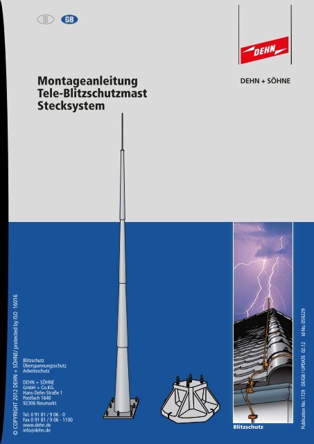
<strong>Montageanleitung</strong><br />
<strong>Tele</strong>-<strong>Blitzschutzmast</strong><br />
<strong>Stecksystem</strong><br />
Blitzschutz<br />
Überspannungsschutz<br />
Arbeitsschutz<br />
<strong>DEHN</strong> + SÖHNE<br />
GmbH + Co.KG.<br />
Hans-Dehn-Straße 1<br />
Postfach 1640<br />
92306 Neumarkt<br />
Tel. 0 91 81 / 9 06 - 0<br />
Fax 0 91 81 / 9 06 - 1100<br />
www.dehn.de<br />
info@dehn.de<br />
Blitzschutz<br />
Publication No. 1729 DE/GB / UPDATE 02.12 Id-No. 059229
Werkzeugbedarf<br />
1 Gabelschlüssel SW 13 (Sechskantschraube M8)<br />
1 Gabelschlüssel SW 30 (Sechskantmutter M20)<br />
2 Gabelschlüssel SW 36 (Sechskantmutter M24)<br />
1 Drehmomentschlüssel<br />
1 Meterstab<br />
1 Kreide/Stift<br />
1 Wasserwaage / Richtlatte<br />
6 Holzklötze ca. 10 x 10 x 50 cm<br />
1 Hartholzklotz<br />
1 Vorschlaghammer<br />
1 Schlupf-Rundschlingen<br />
1 Löseseil<br />
Kran zum Entladen/Setzen des Fertigteilfundaments und zum Setzen der Masten.<br />
Seite 2<br />
MO_1729_DE_GB_0212_059229
1. <strong>Tele</strong>-<strong>Blitzschutzmast</strong> / <strong>Stecksystem</strong><br />
Für bauliche Anlagen und Konstruktionen mit einfacher Bauform ist es zweckmäßig, die<br />
Schutzwinkelmethode zu verwenden. Bis zu einer Gesamthöhe von 60 m können Fangstangen errichtet<br />
werden, denen ein kegelförmiger Schutzraum entsprechend Bild 1 zugeordnet wird. Die Werte α des<br />
Schutzwinkels sind abhängig von der Blitzschutzklasse und Höhe der Fangstange.<br />
Der Trennungsabstand "s" zwischen der Fangstange und dem zu schützenden Objekt ist nach<br />
DIN EN 62305-3 (VDE 0185-305-3) einzuhalten.<br />
Ein Beispiel für die Fangeinrichtung einer Biogas-Anlage mit <strong>Tele</strong>-<strong>Blitzschutzmast</strong>en zeigt Bild 2.<br />
h1<br />
α°<br />
α°<br />
Bild 1 Schutzwinkel<br />
Figure 1 Protective angle<br />
Der Winkel α ist<br />
abhängig von der<br />
Schutzklasse<br />
und Höhe des<br />
<strong>Blitzschutzmast</strong>es<br />
über dem Erdboden<br />
Bild 2 Biogas-Anlage mit <strong>Tele</strong>-<strong>Blitzschutzmast</strong><br />
Seite 3<br />
α°<br />
80<br />
70<br />
60<br />
50<br />
40<br />
30<br />
20<br />
10<br />
0<br />
Schutzwinkelverfahren<br />
I<br />
II III<br />
0 2 10 20 30 40 50 60<br />
h[m]<br />
Sicherheitshinweise<br />
Die Montage des <strong>Tele</strong>-<strong>Blitzschutzmast</strong>en darf<br />
nur durch eine anerkannte Blitzschutzfachkraft<br />
erfolgen.<br />
Die nationalen Vorschriften und Sicherheitsbestimmungen<br />
sind zu beachten.<br />
Vor der Montage ist der <strong>Tele</strong>-Blitzschutz-mast<br />
auf äußere Beschädigung zu kontrollieren.<br />
Sollte eine Beschädigung oder ein sonstiger<br />
Mangel festgestellt werden, darf der <strong>Tele</strong>-<br />
<strong>Blitzschutzmast</strong> nicht montiert und aufgestellt<br />
werden.<br />
Das Aufstellen des <strong>Tele</strong>-<strong>Blitzschutzmast</strong>en ist<br />
nur im Rahmen der in dieser <strong>Montageanleitung</strong><br />
genannten und gezeigten<br />
Bedingungen zulässig. Zusätzliche Anbauten<br />
und Veränderungen am <strong>Tele</strong>-Blitzschutz-<br />
masten führen zum Erlöschen des Gewährleistungsanspruches.<br />
IV<br />
MO_1729_DE_GB_0212_059229
<strong>Tele</strong>-<strong>Blitzschutzmast</strong>e sind in verschiedenen Längen lieferbar. Die entsprechenden techn. Daten können<br />
aus den Tabellen 1, 2 und 4 entnommen werden. Weitere Längen sind auf Anfrage möglich.<br />
Die <strong>Tele</strong>-<strong>Blitzschutzmast</strong>e sind für eine Windgeschwindigkeit bis 161 km/h (Staudruck bis 1,3 kN / m 2)<br />
dimensioniert (Windzone III nach DIN 4131). Die Gründung muss auf tragfähigem Boden mit einer<br />
zulässigen Bodenpressung von mindestens 200 kN/m 2 erfolgen.<br />
2. Variante A:<br />
<strong>Tele</strong>-<strong>Blitzschutzmast</strong> für vorgefertigtes Köcherfundament (KöFU).<br />
1<br />
2<br />
3<br />
4<br />
5<br />
Tabelle 1<br />
<strong>Blitzschutzmast</strong> Stahl/tZn mit Flanschplatte<br />
Bauteil Art.-Nr. Gewicht Gesamt- Bezeichnung<br />
ca. höhe<br />
103 013 228 kg 13,35 m<br />
103 016<br />
103 019<br />
103 022<br />
103 025<br />
Max. Transportlänge:<br />
Das oberste Mastsegment Nr. 1 hat eine Länge von 6 m<br />
230 kg<br />
310 kg<br />
450 kg<br />
550 kg<br />
16,35 m<br />
19,35 m<br />
22,35 m<br />
24,85 m<br />
<strong>Blitzschutzmast</strong> 2-teilig,<br />
konisch, und Fangstange<br />
2,4 m, für Köcherfundament<br />
I mit 2,5 t<br />
<strong>Blitzschutzmast</strong> 2-teilig,<br />
konisch, und Fangstange<br />
5,4 m, für Köcherfundament<br />
I mit 2,5 t<br />
<strong>Blitzschutzmast</strong> 3-teilig,<br />
konisch, und Fangstange<br />
5,4 m, für Köcherfundament<br />
I mit 2,5 t<br />
<strong>Blitzschutzmast</strong> 4-teilig,<br />
konisch, und Fangstange<br />
5,4 m, für Köcherfundament<br />
II mit 4,9 t<br />
<strong>Blitzschutzmast</strong> 5-teilig,<br />
konisch, und Fangstange<br />
5,4 m, für Köcherfundament<br />
II mit 4,9 t<br />
∅<br />
Das Mastsystem besteht laut Skizze links aus 2 bis 5 konischen<br />
Mastsegmenten. Auf diese wird zusätzlich eine Fangstange<br />
aus Stahl/tZn (∅ 42 / ∅ 20 / ∅ 10 mm) montiert,<br />
Fangstangenlänge 5,4 m bzw. 2,4 m beim 13,35 m Mast.<br />
Am Mastfuß befindet sich eine Flanschplatte passend zum<br />
Ankerkorb im Köcherfundament / Betonfundament vor Ort.<br />
Seite 4<br />
MO_1729_DE_GB_0212_059229
2. Variante A:<br />
<strong>Tele</strong>-<strong>Blitzschutzmast</strong> für vorgefertigtes Köcherfundament (KöFU).<br />
Bauteil<br />
Tabelle 2<br />
Köcherfundament<br />
Art.-Nr. Bezeichnung Abmessung (m)<br />
l / b / h<br />
103 030 KöFU I 1,8 / 2 / 0,85 2,5 t<br />
103 031 KöFU II 2,4 / 2,4 / 1,01 4,9 t<br />
Transportöse<br />
Gewicht Verwendung<br />
Das Köcherfundament ist bis zur Bodengleiche mit Erdaushub<br />
zu verfüllen. Der Erdaushub ist leicht zu verdichten.<br />
Bild 3a Fundamentgrube mit Sandbett Bild 3b Köcherfundament KöFU I<br />
Seite 5<br />
Mastlängen:<br />
13,35 m - 19,35 m<br />
Windzone III<br />
Mastlängen:<br />
22,35 m - 24,85 m<br />
Windzone III<br />
2.1 Montage Köcherfundament<br />
Für das Köcherfundament ist ein Erdaushub durchzuführen. Beim Erdaushub für das Köcherfundament<br />
sind die angegebenen Maße zu berücksichtigen. Es empfiehlt sich, aus arbeitstechnischen Gründen die<br />
Maße für den Erdaushub etwas größer zu wählen (siehe Bild 3a und Bild 3b).<br />
Empfohlene Maße für den Erdaushub, KöFU I ca. 2,5 m x 2,5 m x 0,90 m<br />
Empfohlene Maße für den Erdaushub, KöFU II ca. 3 m x 3 m x 1,05 m<br />
Nach Ausheben der Fundamentgruben werden ca. 3 -5 cm Sand oder bei größeren Auffüllungen<br />
Mineralbeton (0-16 mm) oder Magerbeton als Ausgleichsschicht eingebracht, leicht verdichtet und eben<br />
abgezogen (siehe Bild 3a und 3b).<br />
MO_1729_DE_GB_0212_059229
Der <strong>Tele</strong>-<strong>Blitzschutzmast</strong> wird auf das vorher vorbereitete Köcherfundament gestellt und damit fest<br />
verschraubt (Anzugsdrehmomemt 150 Nm).<br />
3. Variante B<br />
Tabelle 3<br />
<strong>Tele</strong>-<strong>Blitzschutzmast</strong><br />
Kontermutter M24<br />
Flanschplatte<br />
Gewindebolzen M24<br />
Beilagscheibe<br />
Sechskantmutter M24<br />
Köcherfundament<br />
Bild 3c Aufstellen der Masten<br />
Ausgleichsschicht<br />
Ringerder mit Anschlussfahne zur Anschlusslasche<br />
<strong>Tele</strong>-<strong>Blitzschutzmast</strong> für ein Betonfundament vor Ort<br />
Abstand zum<br />
nachträglichen<br />
Ausrichten!<br />
Die Fundamentgründung kann auch vor Ort im Rahmen einer Baumaßnahme errichtet werden.<br />
Für die Variante B sind je nach Masttyp getrennte Ankerkörbe separat zu bestellen. Die Ankerkörbe<br />
sind bei der Errichtung vor Ort in die Fundamentgründung mit einzubetonieren.<br />
Auf senkrechte Positionierung des Ankerkorbes ist zu achten!<br />
Art.-Nr. <strong>Blitzschutzmast</strong> 103 013 103 016 103 019 103 022 103 025<br />
Höhe über Flur (h in m) 13,35 16,35 19,35 22,35 24,85<br />
Fundament (a x b in mm) 1400 x 1400 1400 x 1400 1600 x 1600 1800 - 1800 2000 - 2000<br />
Gründungstiefe (c in mm) 900 900 900 900 900<br />
Gewicht (ca. kg) 228 230 310 450 550<br />
Seite 6<br />
Erdungsanschluss<br />
Anschlusslasche<br />
(Bohrung, Ø 12 mm)<br />
Möglicher Anschluss<br />
über KS-Verbinder<br />
z.B. Art.-Nr. 301 019<br />
MO_1729_DE_GB_0212_059229
3.1 Fundamentanforderungen<br />
Für den <strong>Tele</strong>-<strong>Blitzschutzmast</strong> ist im Vorfeld (ca. 3 Wochen) ein Betonfundament (mindestens C 20/25)<br />
zu errichten. Dieses Blockfundament sollte mit einer Köcherbewehrung (Bewehrungseisen ∅ 12 mm)<br />
ausgestattet werden, dadurch wird ein besserer Verbund erreicht. Die Bewehrungseisen sind mit einem<br />
Abstand von ca. 20 - 30 cm als Ring zu verlegen.<br />
Die Gründungstiefe c und die Abmessungen des Betonfundamentes a x b x c für die Maste sind der<br />
Tabelle 3, Seite 6 zu entnehmen (siehe auch Bild 4, Seite 8).<br />
Für die Variante B sind je nach Masttyp getrennte Ankerkörbe separat zu bestellen. Die Ankerkörbe sind<br />
bei der Errichtung vor Ort in die Fundamentgründung lotrecht auszurichten und einzubetonieren (siehe<br />
Tabelle 4, Seite 7 und Bild 4, Seite 8) .<br />
Die benötigte Länge der Gewindebolzen von 140 mm ist zu beachten.<br />
Art.-Nr.<br />
Mast<br />
103 013<br />
103 016<br />
103 019<br />
103 022<br />
103 025<br />
Tabelle 4<br />
Gewindebolzen<br />
M24<br />
Art.-Nr.<br />
Ankerkorb<br />
103 040<br />
103 041<br />
Oberkante<br />
Fundament<br />
870 mm<br />
Oberkante<br />
Fundament<br />
870 mm<br />
Seite 7<br />
245 mm<br />
Maßbild<br />
300 mm 140 mm<br />
490 mm<br />
Die benötigte Länge der<br />
Gewindebolzen von<br />
140 mm ist zu beachten.<br />
140 mm<br />
Die benötigte Länge der<br />
Gewindebolzen von<br />
140 mm ist zu beachten.<br />
MO_1729_DE_GB_0212_059229
Beim Zusammenschrauben des <strong>Tele</strong>-<strong>Blitzschutzmast</strong>es<br />
mit dem jeweiligen Ankerkorb ist ein<br />
Anzugsdrehmomemt von 150 Nm anzuwenden!<br />
<strong>Tele</strong>-<strong>Blitzschutzmast</strong><br />
Kontermutter M24<br />
Flanschplatte<br />
Gewindebolzen M24<br />
Sechskantmutter M24<br />
Beton<br />
(C 20/25)<br />
Bewehrungseisen<br />
Erdreich<br />
Ankerkorb<br />
Bild 4 Betonfundament mit Bewehrung<br />
Ringerder mit Anschlussfahne<br />
Fundament a x b in mm<br />
Seite 8<br />
Abstand der Bewehrungseisen<br />
ca. 200-300 mm<br />
ca. 300 mm<br />
zur Anschlusslasche c = Gründungstiefe<br />
Erdungsanschluss<br />
Anschlusslasche<br />
(Bohrung, 12 mm)<br />
Möglicher Anschluss<br />
über KS-Verbinder<br />
z.B. Art.-Nr. 301 019<br />
Abstand zum<br />
nachträglichen<br />
Ausrichten!<br />
140 mm<br />
MO_1729_DE_GB_0212_059229
4. Aufstellung des <strong>Tele</strong>-<strong>Blitzschutzmast</strong>es<br />
Das Konstruktionsprinzip der <strong>Tele</strong>-<strong>Blitzschutzmast</strong>e besteht aus einer Anzahl von konischen Mast-<br />
segmenten (Mastteilen), die zu einer Einheit zusammengesteckt werden. Die Längsschweißnähte<br />
müssen dabei in gleicher Flucht liegen. Vor dem Zusammenfügen wird am Mastunterteil die<br />
Übersteckung nach VDE 0210 (EN 50341-1) von 300-400 mm (Mastsegment (1+2 / 2+3 ) bzw.<br />
400-500 (Mastsegment (3+4 / 4+5) mm markiert (siehe Bild 5 und Tabelle 1).<br />
Hinweis:<br />
Die Mastsegmente (Mastteile) sind vor der Montage auf mögliche Transportschäden hin zu<br />
überprüfen.<br />
Flanschplatte<br />
Schweißnaht 300-400 mm<br />
Mastsegment<br />
Bild 5 <strong>Tele</strong>-<strong>Blitzschutzmast</strong><br />
Übersteckung evtl.<br />
mit Kreide anzeichnen<br />
400-500 mm<br />
4.1 Aufstellung: Mastsegment für Mastsegment<br />
Seite 9<br />
Mastsegment<br />
Das unterste Mastsegment (mit Flanschplatte) wird auf die Gewindebolzen M24 gestellt, ausgerichtet<br />
und fixiert. Alle weiteren Mastsegmente können z.B. mit nem Kran aufgesetzt und bis zur Übersteck-<br />
ung zusammengefügt werden.<br />
Zum einfacheren Zusammenstecken ist zusätzlich eine Arbeitsbühne empfehlenswert.<br />
4.2 Aufstellung: gesamter Mast<br />
Die Mastsegmente werden mit dem untersten Mastsegment beginnend, am Aufstellort aneinander-<br />
gereiht ausgelegt (siehe Bild 5). Zur Steckstoßmontage Mastunterteil und Mastoberteil evtl. auf ein<br />
Kantholz auflegen. Dabei ist auf die Ausrichtung des Mastes zu achten. Anschließend am oberen<br />
Mastende ein Kantholz (Hartholz) beilegen und die Teile mit einem Vorschlaghammer (Gewicht ≥ 5kg)<br />
bis zur Markierung der Übersteckung zusammentreiben. Das unterste Mastsegment benötigt ein<br />
massives Widerlagen (siehe Bild 6, Seite 10).<br />
Anmerkung:<br />
Ein direktes Schlagen mit dem Vorschlaghammer auf die Mastsegmente ist wegen Beschädigung der<br />
Zinkschicht zu unterlassen. (siehe Bild 6, Seite 10).<br />
MO_1729_DE_GB_0212_059229
Vor dem Aufrichten des <strong>Tele</strong>-<strong>Blitzschutzmast</strong>es ist die Fangstange zu montieren. Festen Paßsitz der<br />
Einzelteile nochmals prüfen. Der gesamte Mast mit Flanschplatte wird lotrecht auf das Fundament<br />
gestellt und bei Bedarf nochmals ausgerichtet.<br />
Widerlager<br />
Kantholz<br />
Bild Bild 6 6 Steckstoßmontage<br />
Steckstoßmontage<br />
Seite 10<br />
Hartholzklotz<br />
MO_1729_DE_GB_0212_059229
4.3 Montage, Mastaufsatz und Fangstange<br />
1<br />
2<br />
Hierbei sind nachfolgende Schritte zu beachten:<br />
- Übersteckung von ca. 150 mm anzeichnen<br />
- Mastaufsatz mit dem unteren Ende<br />
(∅ 116 mm) auf das oberste Mastsegment<br />
aufsetzen (evtl. leicht mit Kantholz aufschlagen)<br />
und mit den acht Arretierungsschrauben (M8)<br />
festschrauben.<br />
Das Anzugsmoment beträgt 10 Nm (siehe Bild 7).<br />
- Fangstange ∅ 42 / ∅ 20 / ∅ 10 mit dem<br />
unterenEnde in den oberen Teil des Mastaufsatzes<br />
(∅ 44 mm) einführen und mit den zwei<br />
Arretierungsschrauben (M8) festschrauben.<br />
- Fangstange mit Sechskantmutter nachziehen.<br />
Das Anzugsmoment beträgt dabei 10 Nm<br />
(siehe Bild 7).<br />
Seite 11<br />
Fangstangenteil<br />
mit ∅ 10 mm<br />
Fangstangenteil<br />
mit ∅ 20 mm<br />
Kontermutter<br />
M20<br />
Unteres Teil des<br />
Mastaufsatzes<br />
1<br />
2<br />
Fangstangenteil<br />
mit ∅42 mm<br />
Mastaufsatz<br />
Arretierungsschraube<br />
M8<br />
Angeschweißte<br />
Mutter M24<br />
Oberes Teil des<br />
Mastaufsatzes<br />
Oberes<br />
Mastsegment<br />
∅ 44 mm<br />
∅ 116 mm<br />
MO_1729_DE_GB_0212_059229
5. Transport vor Ort und Aufstellung des <strong>Tele</strong>-<strong>Blitzschutzmast</strong>es.<br />
Es empfiehlt sich der Einsatzes eines Autokrans.<br />
Der Mast ist für die Positionierung im oberen Drittel anzuhängen.<br />
Die Aufhängung sollte nicht mit einem Seil erfolgen, da dieses sich anschließend schlecht vom Mast<br />
lösen lässt. Empfohlen wird ein breiter Schlupf/Rundschlinge (siehe Bild 8).<br />
Über die Gewindebolzen ist ein geringes Ausrichten des <strong>Blitzschutzmast</strong>es möglich.<br />
Zum einfachen Lösen des Schlupfes/Rundschlinge kann ein Löseseil mit verwendet werden.<br />
Bild 8 Transport<br />
Bild 6 Steckstoßmontage<br />
6. Erdungsanlage<br />
Die Erdung des <strong>Tele</strong>-<strong>Blitzschutzmast</strong>es erfolgt über die Lasche (mit Bohrung, ∅ 12 mm für Rundleiter<br />
∅ 10 mm, z.B. mit KS-Verbinder Art.-Nr. 301019) an der Flanschplatte. Diese Erdung soll mit der<br />
Erdungsanlage des zu schützenden Objektes verbunden werden (vermaschte Erdungsanlage). Ist keine<br />
Gebäudeerdungsanlage vorhanden, muss eine eigene Erdungsanlage nach DIN EN 62305-3 (VDE<br />
0185-305-3) errichtet werden.<br />
Der Erdanschluss an den Mast / Flanschplatte (Anschlussfahne) ist vorzugsweise mit dem Werkstoff<br />
NIRO (V4A) oder Stahl feuerverzinkt (mit Schrumpfschlauch umhüllt) zu erstellen.<br />
Seite 12<br />
MO_1729_DE_GB_0212_059229
Notizen<br />
Seite 13<br />
MO_1729_DE_GB_0212_059229
Notizen<br />
Seite 14 MO_1729_DE_GB_0212_059229
Notizen<br />
Seite 15<br />
MO_1729_DE_GB_0212_059229
© 2012 <strong>DEHN</strong> + SÖHNE/ protected by ISO 16016<br />
Blitzschutz<br />
Überspannungsschutz<br />
Arbeitsschutz<br />
<strong>DEHN</strong> + SÖHNE<br />
Hans-Dehn-Straße 1<br />
Postfach 1640<br />
92306 Neumarkt<br />
Tel. 0 91 81 / 9 06 - 0<br />
Fax 0 91 81 / 9 06 - 1100<br />
www.dehn.de<br />
info@dehn.de
© COPYRIGHT 2012 <strong>DEHN</strong> + SÖHNE/ protected by ISO 16016<br />
Installation Instructions<br />
<strong>Tele</strong>scopic Lightning Protection Mast<br />
Plug-in System<br />
Lightning Protection<br />
Surge Protection<br />
Safety Equipment<br />
<strong>DEHN</strong> + SÖHNE<br />
GmbH + Co.KG.<br />
Hans-Dehn-Str. 1<br />
Postfach 1640<br />
92306 Neumarkt<br />
Germany<br />
Tel.:. + 49 91 81 / 9 06-0<br />
Fax.: + 49 91 81 / 9 06 -1100<br />
www.dehn.de<br />
info@dehn.de<br />
Lightning Protection<br />
Publication No. 1729 DE/GB / UPDATE 02.12 Id-No. 059229
Tools<br />
1 13 mm open-end spanner (M8 hexagon screw)<br />
1 30 mm open-end spanner (M20 hexagon screw)<br />
2 36 mm open-end spanner (M24 hexagon screw)<br />
1 Torque spanner<br />
1 Folding meter stick<br />
1 Chalk / pen<br />
1 Water level / straightedge<br />
6 wood logs approx. 10 x 10 x 50 cm<br />
1 hard wood log<br />
1 Sledge hammer<br />
1 Loop/round slings<br />
1 Loosening rope<br />
Crane for unloading/positioning the foundation and for positioning the masts<br />
Page 2<br />
MO_1729_DE_GB_0212_059229
1. <strong>Tele</strong>scopic Lightning Protection Mast / Plug-in System<br />
For buildings and constructions with a simple structure and design, the protective angle methode is<br />
expedient. On buildings up to a total height of 60 m air-termination rods can be installed. The cone<br />
shaped protected area of air-termination rods is illustrated in Figure 1. The values α of the protective<br />
angle are dependent on the class of LPS (lightning protection system) and on the height of the<br />
air-termination rod. The separation distance "s" between the air-termination rod and the structure to<br />
be protected has to be kept in accordance with DIN EN 62305-3 (VDE 0185-305-3).<br />
Figure 2 shows an example of an air-termination system at a biogas plant with telescopic lightning<br />
protection masts.<br />
h1<br />
α°<br />
α°<br />
Figure 1 Protective angle<br />
Angle α is a function<br />
of the class of LPS and<br />
the height of the<br />
lightning protection<br />
mast above ground<br />
level<br />
α°<br />
80<br />
70<br />
60<br />
50<br />
40<br />
30<br />
20<br />
10<br />
0<br />
Figure 2 Biogas plant with telescopic lightning protection masts<br />
Page 3<br />
Protective Angle Method<br />
I<br />
II III<br />
0 2 10 20 30 40 50 60<br />
h[m]<br />
Safety Note<br />
<strong>Tele</strong>scopic lightning protection masts may<br />
only be installed by recognised lightning<br />
protection specialists.<br />
National rules and safety regulations have<br />
to be observed.<br />
Before installation, the telescopic lightning<br />
protection mast has to be checked for<br />
outside damage.<br />
In case of any damage or flaw detected,<br />
the telescopic lightning protection mast<br />
must not be mounted or set up.<br />
Installation of the telescopic lightning<br />
protection mast is only allowed within the<br />
scope of the terms and conditions mentioned<br />
and shown in these installation<br />
instructions. Additions or changing of the<br />
telescopic lightning protection mast will<br />
void the warranty.<br />
IV<br />
MO_1729_DE_GB_0212_059229
<strong>Tele</strong>scopic lightning protection masts are available in different lengths. For the corresponding technical<br />
data please see Tables 1, 2 and 4. Upon request further lengths are available. The telescopic lightning<br />
protection masts are dimensioned for a dynamic pressure up to 1.3 kN / m² (wind zone III acc. to DIN<br />
4131). Foundation has to be effected on good bearing soil with an admissible soil loading of at least<br />
200 kN/m².<br />
2. Model A:<br />
<strong>Tele</strong>scopic lightning protection mast for prefabricated bucket foundation.<br />
1<br />
2<br />
3<br />
4<br />
5<br />
Table 1<br />
Lightning Protection Mast (St/tZn) With Flange Plate<br />
Component Part No. Weight<br />
approx.<br />
Max. transport length:<br />
The top mast segment No. 1 is 6 m long<br />
Total<br />
height<br />
103 013 228 kg 13,35 m<br />
103 016 230 kg 16,35 m<br />
103 019 310 kg 19,35 m<br />
103 022 450 kg 22,35 m<br />
103 025 550 kg 24,85 m<br />
Designation<br />
Lightning protection mast<br />
2-part, conic, and airtermination<br />
rod 2.4 m, for<br />
bucket foundation I of 2.5 t<br />
Lightning protection mast<br />
2-part, conic, and airtermination<br />
rod 5.4 m, for<br />
bucket foundation I of 2.5 t<br />
Lightning protection mast<br />
3-part, conic, and airtermination<br />
rod 5.4 m, for<br />
bucket foundation of 2.5 t<br />
Lightning protection mast<br />
4-part, conic, and airtermination<br />
rod 5.4 m, for<br />
bucket foundation II of 4.9 t<br />
Lightning protection mast<br />
5-part, conic, and airtermination<br />
rod 5.4 m, for<br />
bucket foundation II of 4.9 t<br />
The mast system as illustrated on the left comprises 2 to 5<br />
conic mast segments. On these additionally an<br />
air-termination rod made of St/tZn (∅42 /∅20 /∅10 mm)<br />
will be installed. Air-termination rod length 5.4 m or 2.4 m<br />
in case of a 13.35 m long mast. At the mast foot you have a<br />
flange plate which fits for the foundation basket in the<br />
bucket foundation / on site concrete foundation.<br />
Page 4<br />
MO_1729_DE_GB_0212_059229
2. Model A:<br />
<strong>Tele</strong>scopic lightning protection mast for prefabricated bucket foundation<br />
Table 2<br />
Component<br />
Part No.<br />
103 030<br />
Bucket foundation<br />
Designation Dimension (m)<br />
l / b / h<br />
bucket<br />
foundation I<br />
103 031 bucket<br />
foundation II<br />
Page 5<br />
1,8 / 2 / 0,85<br />
2,4 / 2,4 / 1,01<br />
Weight Use<br />
2,5 t<br />
4,9 t<br />
mast lengths:<br />
13,35 m - 19,35 m<br />
wind zone III<br />
mast lengths:<br />
22,35 m - 24,85 m<br />
wind zone III<br />
2.1 Installation of the bucket foundation<br />
Excavate the foundation pit. For procedural and practical reasons, make sure that the size is a little<br />
bit larger than required for the bucket foundation. (see Figure 3a and 3b).<br />
Bucket foundation I - recommended excavation: 2,5 m x 2,5 m x 0,90 m<br />
Bucket foundation II - recommended excavation: 3 m x 3 m x 1,05 m<br />
After excavation of the foundation pit, fill in a levelling layer of approx. 3 – 5 cm sand, of wet mix<br />
aggregate (0 – 16 mm) or lean concrete, slightly ram this layer and finally level it (see Figure 3a and<br />
3b).<br />
transport eye<br />
Put in the bucket foundation and backfill up to ground<br />
surface level. Ram the backfill slightly.<br />
Figure 3a Foundation pit with sand bed Figure 3b Bucket foundation I<br />
MO_1729_DE_GB_0212_059229
Put the telescopic lightning protection mast on the prepared bucket foundation and fix it tightly with<br />
the screws (tightening torque 150 Nm).<br />
3. Model B<br />
telescopic lightning protection mast<br />
lock nut M24<br />
flange plate<br />
threaded bolt M24<br />
flat washer<br />
hexagon nut M24<br />
bucket foundation<br />
sand bed<br />
Distance for<br />
subsequent levelling!<br />
Ring earth electrode with terminal lug to the connecting bracket<br />
Figure 3c How to set up the mast<br />
<strong>Tele</strong>scopic lightning protection mast for on-site concrete foundation<br />
The foundation foot can also be established onsite.<br />
For Model B individual foundation baskets have to be ordered according to the mast type. These<br />
foundation baskets have to be cast on site into the foundation. Make sure that the foundation basket<br />
is positioned vertically!<br />
Lightning protection mast Part No. 103 013 103 016 103 019 103 022 103 025<br />
Height above ground level (h in m) 13,35 16,35 19,35 22,35 24,85<br />
Foundation (a x b in mm) 1400 x 1400 1400 x 1400 1600 x 1600 1800 - 1800 2000 - 2000<br />
Grounding depth (c in mm) 900 900 900 900 900<br />
Weight (approx. kg) 228 230 310 450 550<br />
Table 3<br />
Page 6<br />
earthing connection<br />
terminal lug<br />
(borehole, ∅ 12 mm)<br />
possible connection<br />
by KS connector<br />
e.g. Part No. 301 019<br />
MO_1729_DE_GB_0212_059229
3.1 Requirements for Foundation<br />
Put up a concrete foundation (at least C 20/25) approx. 3 weeks before setting up the telescopic lightning<br />
protection mast. These foundation blocks shall be equipped with a bucket reinforcement (reinforcement<br />
steel Ø 12 mm) for better interconnection. The distance between the reinforcement steel rings shall be<br />
approx. 20 – 30 cm.<br />
Dimensions a x b x c of the concrete foundation for the masts are indicated in Table 3, page 6 (see also<br />
Figure 4, page 8).<br />
For Model B foundation baskets have to be ordered separately, according to the mast type.<br />
The foundation baskets have to be cast on site into the foundation footing (see Table 4, page 7 and<br />
Figure 4, page 8).<br />
Part No.<br />
Mast<br />
103 013<br />
103 016<br />
103 019<br />
103 022<br />
103 025<br />
Table 4<br />
Threaded<br />
bolt<br />
M24<br />
Part No.<br />
Foundation<br />
basket<br />
103 040<br />
103 041<br />
top edge of the<br />
foundation<br />
870 mm<br />
top edge of the<br />
foundation<br />
870 mm<br />
Page 7<br />
Dimension drawing<br />
300 mm 140 mm<br />
245 mm 140 mm<br />
490 mm<br />
The threaded bolts have<br />
to be 140 mm long<br />
The threaded bolts have<br />
to be 140 mm long<br />
MO_1729_DE_GB_0212_059229
Screw the telescopic lightning protection mast<br />
on the corresponding foundation basket with<br />
a tightening torque of 150 Nm!<br />
telescopic lightning protection mast<br />
lock nut M24<br />
flange plate<br />
threaded bolt M24<br />
hexagon nut M24<br />
concrete<br />
(C 20/25)<br />
reinforcement<br />
steel<br />
soil<br />
foundation<br />
basket<br />
ring earth electrode with terminal<br />
lug to the terminal bracket<br />
foundation a x b in mm<br />
Figure 4 Concrete foundation with reinforcement<br />
Page 8<br />
distance between the<br />
steel ca. 300 reinforcement mm<br />
approx. 200-300 mm<br />
earth connection<br />
terminal lug<br />
(borehole, Ø 12 mm)<br />
possible connection<br />
with KS connector<br />
e.g. Part No. 301 019<br />
Distance for subsequent<br />
levelling!<br />
c = foundation depth<br />
140 mm<br />
MO_1729_DE_GB_0212_059229
4. Installation of the <strong>Tele</strong>scopic Lightning Protection Mast<br />
<strong>Tele</strong>scopic lightning protection masts consist of a quantity of conic segments, which are plugged together<br />
to one unit. Make sure that the longitudinal weld is in line. Mark the telescoping depth in accordance<br />
with EN 50341-1 (VDE 0210) of 300 - 400 mm (mast segment 1+2/2+3) respectively<br />
400 - 500 mm (mast segment 3+4/4+5) at the bottom mast segment before joining. (see Figure 5 and<br />
Table 1).<br />
Note:<br />
Check the mast segments (mast parts) for any transport damage before mounting.<br />
flange plate<br />
weld<br />
mast segment<br />
mark the telescoping depth<br />
e.g. with chalk<br />
300-400 mm<br />
400-500 mm<br />
Figure 5 <strong>Tele</strong>scopic lightning protection mast<br />
4.1 Set-up of mast segments<br />
Page 9<br />
mast segment<br />
Position the bottom mast segment (with flange plate) on the threaded bolts M24, then level and fix it.<br />
Any futher mast segments can be put on e.g. with a crane and pushed down to the marking.<br />
A working platform is recommended to facilitate the assembly.<br />
4.2 Set-up of the complete mast<br />
Arrange the mast segments accurately on the installation site. Put a squared timber under the mast<br />
segments (see Figure 5 and 6). Join one segment with the other. Make sure that the mast is aligned.<br />
<strong>Tele</strong>scope the mast segments with a seldge hammer (weight ≥ 5 kg), using a piece of wood plate (hard<br />
wood) to protect the mast, as deep as the marking shows. At the bottom mast segment you need a<br />
massive end trestle (see Figure 6, page 10).<br />
Note:<br />
The zinc layer might be damaged if you hammer directly on the mast segments without pad (see Figure<br />
6, page 10).<br />
MO_1729_DE_GB_0212_059229
Install the air-termination rod before erecting the telescopic lightning protection mast. Make sure that<br />
the individual parts fit tightly. Position the complete mast with flange plate on the foundation and level<br />
it out.<br />
end trestle<br />
squared timber<br />
Bild Bild Figure 6 6 6 Steckstoßmontage<br />
Steckstoßmontage<br />
<strong>Tele</strong>scoping<br />
Page 10<br />
hard wood<br />
MO_1729_DE_GB_0212_059229
4.3 Mounting of mast support and air-termination rod<br />
1<br />
2<br />
Proceed as follows:<br />
- Mark the telescoping depth of approx. 150 mm<br />
- Insert the mast support (Ø 116 mm)<br />
on top of the mast segment (if necessary<br />
strike slightly with a squared timber) and tighten<br />
the eight fixing screws (M8). The tightening<br />
torque is 10 Nm (see Figure 7)<br />
- Insert the air-termination rod Ø 42 mm /<br />
Ø 20 mm / Ø 10 mm into the mast support<br />
(Ø 44 mm) and tighten the two fixing screws<br />
(M8).<br />
- Fix the air-termination rod with the hexagon<br />
nut. The tightening torque is 10 Nm<br />
(see Figure 7).<br />
Page 11<br />
air-termination rod<br />
segment with ∅ 10 mm<br />
air-termination rod<br />
segment with ∅ 20 mm<br />
lock nut M20<br />
welded on nut M24<br />
1<br />
2<br />
air-termination rod<br />
segment with ∅ 42 mm<br />
top of mast<br />
support<br />
mast support<br />
bottom of mast<br />
support<br />
fixing screw<br />
M8<br />
top of mast<br />
segment<br />
∅ 44 mm<br />
∅ 116 mm<br />
MO_1729_DE_GB_0212_059229
5. On-site Transport and Set-up of the <strong>Tele</strong>scopic Lightning Protection Mast<br />
Using a truck-mounted crane is recommended.<br />
Attach the mast in the upper third for positioning.<br />
Better not use a rope as hook (difficult to detach it afterwards) but rather a wide loop/round sling<br />
(see Figure 8).<br />
The threaded bolts allow for a slight adjustment of the lightning protection mast.<br />
A loosening rope can be used to detach the loop/round sling easily.<br />
Figure 8 Transport<br />
Bild 6 Steckstoßmontage<br />
6. Earth-termination System<br />
Earthing of the telescopic lightning protection mast is implemented at the lug (with borehole Ø 12<br />
mm) of the flange plate. This earth termination shall be connected with the earth-termination system<br />
of the object to be protected (intermeshed earthing system). If there is no building earth-termination<br />
system, an own earth-termination system according to DIN EN 62305-3 (VDE 0185-305-3) has to be<br />
provided.<br />
StSt (V4A) or galvanised steel (with heat-shrinkable sleeve enclosure) is the prefered material to be<br />
used for the earth connection at the mast / flange plate.<br />
Page 12<br />
MO_1729_DE_GB_0212_059229
Note<br />
Page 13<br />
MO_1729_DE_GB_0212_059229
Note<br />
Page 14 MO_1729_DE_GB_0212_059229
Note<br />
Page 15<br />
MO_1729_DE_GB_0212_059229
© 2012 <strong>DEHN</strong> + SÖHNE/ protected by ISO 16016<br />
Lightning Protection<br />
Surge Protection<br />
Safety Equipment<br />
<strong>DEHN</strong> + SÖHNE<br />
Hans-Dehn-Straße 1<br />
Postfach 1640<br />
92306 Neumarkt<br />
Germany<br />
Tel. +49 9181 906 0<br />
Fax +49 9181 906 1100<br />
www.dehn.de<br />
export@dehn.de