Edelstahl-Pressfittings - AVAG-Pumpen
Edelstahl-Pressfittings - AVAG-Pumpen
Edelstahl-Pressfittings - AVAG-Pumpen

Erfolgreiche ePaper selbst erstellen
Machen Sie aus Ihren PDF Publikationen ein blätterbares Flipbook mit unserer einzigartigen Google optimierten e-Paper Software.
<strong>AVAG</strong>-<strong>Pumpen</strong> Import-Export GmbH<br />
Leiberger Str. 27<br />
33181 Bad Wünnenberg<br />
Tel. 02953/98060 - Fax 02953/980630<br />
Bedienungsanleitung<br />
®<br />
Technical<br />
Guide
Made<br />
in Italy<br />
STAINLESS STEEL<br />
AISI 316L<br />
ISO 9001:2000<br />
INTERNATIONALE<br />
ZULASSUNGEN<br />
International<br />
certicates<br />
Die Qualität der eingesetzten<br />
Werkstoe und die rigorose<br />
Qualitätskontrolle haben dazu<br />
beigetragen, dass das<br />
Presstting-System die<br />
Konformitätsbescheinigungen<br />
der strengsten europäischen<br />
Zertizierungen erhalten<br />
hat.<br />
The quality of used<br />
materials and the<br />
adoption of a rigorous<br />
quality control allowed<br />
Presstting system<br />
to obtain the conformity<br />
with the most<br />
severe European<br />
certications.<br />
Germany<br />
France *<br />
England *<br />
Norway<br />
Sweden<br />
Austria *<br />
Netherlands<br />
Switzerland<br />
Finland<br />
Denmark *<br />
Italy<br />
Russia<br />
SOON AVAILABLE:<br />
Poland<br />
product<br />
W534 - water<br />
VP 614 - gas<br />
* Inhaber der Zulassung: unser Vertreter<br />
Approval obtained directly by our distributor<br />
also for<br />
CUPRONICKEL<br />
also for<br />
CARBON STEEL<br />
also for<br />
CARBON STEEL<br />
also for<br />
CARBON STEEL<br />
NKB 12 - heating systems<br />
W 1.402 - water<br />
G 2.827 - gas
1. EINFÜHRUNG<br />
Das Press tting-System ist ein extrem einfaches und<br />
montagefreundliches Pressverbindungs - System für Rohre,<br />
das die Herstellung von Rohrleitungsanlagen im Wohnungs-<br />
, Industrie- und im Schisbaubereich mit zuverlässigen und<br />
unlösbaren längskraftschlüssigen Verbindungen ermöglicht.<br />
Der Bereich der lieferbaren Durchmesser reicht von 12 bis 108 mm.<br />
1.1 Werkstoe<br />
Je nach Anwendungsbereich werden die Produkte aus<br />
folgenden Werkstoen hergestellt:<br />
- <strong>Edelstahl</strong><br />
- C-Stahl<br />
- Kupfer-Nickel-Legierung<br />
1.2 Verarbeitungs - Vorteile<br />
Die Hauptvorteile des Press tting-Systems sind:<br />
- Einfache, schnelle und sichere Montage<br />
- Zuverlässige und dauerhafte Abdichtung zwischen Rohr und Fitting<br />
- Kein Brandgefahr bei der Installationsarbeit<br />
- Korrosions – Beständigkeit<br />
2. SYSTEMBESCHREIBUNG<br />
2.1 Allgemeines<br />
Das Press tting-System besteht aus folgenden<br />
Komponenten:<br />
Pressttings<br />
Sie sind die Grundbausteine des Systems. An jedem Ende<br />
weisen sie eine ringförmige Aufnahme auf, in die der Dichtring<br />
aus Kunstkautschuk eingesetzt wird. Sie sind in verschiedenen<br />
Typologien erhältlich (siehe Produktkatalog), von denen einige<br />
auch für Flansch-, Gewinde- und Schweißverbindungen<br />
verschiedener Materialien eingesetzt werden können.<br />
Rohre<br />
Sie stellen das zweite Element des Systems dar und sind auf dem<br />
Markt erhältlich. Sie müssen jedoch den technischen Angaben<br />
entsprechen, die für die verschiedenen Anwendungen in den<br />
folgenden Kapitel 3, 4 und 5 erläutert werden.<br />
Presswerkzeuge<br />
Hierbei handelt es sich um handelsübliche Produkte, die zur Verpressung<br />
der Fittings auf den Systemrohren dienen. technischen Angaben<br />
entsprechen, die im folgenden Kapitel 2.3 beschrieben werden.<br />
1. INTRODUCTION<br />
Bedienungsanleitung 3 Technical Guide<br />
PRESSFITTING SYSTEM<br />
The Press tting System is an extremely fast and simple<br />
press tting assembly system, producing reliable joints with high<br />
mechanical resistance, for civil, industrial and naval pipework<br />
system installations.<br />
Range of diameters from 12 to 108 mm.<br />
1.1 Materials<br />
Depending on the application, the following materials are used:<br />
- stainless steel<br />
- carbon steel<br />
- cupronickel<br />
1.2 Benets<br />
The main bene ts of the Press tting System are:<br />
- fast and easy assembly<br />
- reliable, secure and long-lasting seals<br />
- no re risk during installation<br />
- high corrosion resistance<br />
2. SYSTEM DESCRIPTION<br />
2.1 General information<br />
The following components make up the Press tting<br />
System:<br />
Pressttings<br />
The basic system component.<br />
Each end has a toroidal seat, holding a synthetic rubber o-ring<br />
gasket. A range of ttings is available (see catalogue), including<br />
some of various materials, which can be used for anged and<br />
threaded connections or welded joints.<br />
Pipes<br />
The second system component. Commercially available pipes may<br />
be used, provided they comply with the technical speci cations<br />
set out in sections 3, 4 and 5 of this manual, detailing the various<br />
applications.<br />
Pressingtools<br />
Used to join the two components, these are also commercially<br />
available and may be used, provided they comply with the<br />
technical speci cations set out at point 2.3 of this manual.
PRESSFITTING SYSTEM<br />
2.2 Pressverfahren<br />
Die Verpressung der Fittings mit den Rohren ist einfach, schnell<br />
und sicher.<br />
Das Rohr wird bis zum Anschlag in die Fittings eingeschoben.<br />
Anschließend wird das ringförmige Ende derselben mit einer von<br />
einem Presswerkzeug betätigten Backe auf das Rohr gedrückt.<br />
Das Verpressen bewirkt zwei Verformungen. Die erste radiale<br />
Verformung komprimiert den O-Ring in der ringförmigen Aufnahme<br />
und gewährleistet die Dichtheit auf dem Rohr. Die zweite verändert<br />
die Geometrie der Verbindung und des Rohres, gewährleistet den<br />
mechanischen Sitz und verhindert das Herausgleiten des Rohrs<br />
und die Drehung zwischen Rohr und Anschluss.<br />
Das Pro l, das durch die Pressung erzielt wird, ändert sich je<br />
nach Durchmesser.<br />
Die Abb. 1 zeigt die Komponenten vor und nach dem<br />
Verpressen im Pro l und im Querschnitt.<br />
Vor Verpressen<br />
Before pressing<br />
Nach Verpressen<br />
After pressing<br />
Presstting<br />
Presstting<br />
Fig. 1 Die Verpressung des Fittings mit dem Rohr Joining of presstting on pipe<br />
Die so erzielte Rohrverbindung verleiht dem System hohe<br />
Festigkeit und gleichzeitig die notwendige Elastizität, um<br />
die Beanspruchungen aufzufangen, die gewöhnlich bei der<br />
Verlegung auftreten oder durch den Betrieb der Anlagen<br />
entstehen (Vibrationen, Wärmedehnungen usw.) unter der<br />
Voraussetzung, dass bei der Installation die im folgenden<br />
Kapitel 7 beschriebenen Anweisungen eingehalten werden.<br />
2.3 Presswerkzeuge<br />
Pro lansicht<br />
Pro le view<br />
O-ring Rohr<br />
Pipe<br />
Das Verpressen erfolgt mittels Presswerkzeugen. Diese sind<br />
mit austauschbaren Pressbacken versehen, die je nach<br />
Durchmesser montiert werden.<br />
2.2 Joining process<br />
Bedienungsanleitung 4 Technical Guide<br />
Press tted pipe joints are fast, easy and risk-free.<br />
The pipe is pushed into the tting, up to the stop, then the jaw<br />
attachments of the pressing tool press the toroidal end of the<br />
tting into the pipe.<br />
Pressing produces two deformations. The rst, radial deformation,<br />
compresses the o-ring in the toroidal chamber and guarantees<br />
that the pipe is hermetically sealed. The second, geometric<br />
deformation of both tting and pipe, creates a mechanical joint,<br />
resistant to slipping and rotation.<br />
The resulting pressing pro le varies according to diameter.<br />
Fig.1 shows the components, in pro le and section views,before<br />
and after pressing.<br />
Ø 12-35<br />
Querschnittansicht<br />
Section view<br />
Joints produced in this way are extremely strong, but exible<br />
enough to withstand the stresses resulting from initial installation<br />
and those, such as vibrations and thermal expansion etc., that<br />
occur in normal operating conditions. This is provided that<br />
installation has been carried out according to the instructions in<br />
section 7 of this manual.<br />
2.3 Pressing tools<br />
Ø 42-108<br />
The pressing process is achieved using pressing tools with a range<br />
of jaw attachments that vary according to the tting and pipe<br />
diameters.
Auf dem Markt werden unterschiedliche Presswerkzeuge<br />
angeboten:<br />
- batterie- oder netzgespeiste elektromechanische<br />
Werkzeuge (220 V – 110 V- 48 V) werden für den gesamten<br />
Durchmesserbereich eingesetzt.<br />
- elektrohydraulische Werkzeuge werden dagegen vornehmlich<br />
für die größeren Durchmesser von 76,1 bis 108 mm verwendet.<br />
Das Presstting-System gestattet die Verwendung von<br />
Presswerkzeugen verschiedener Art, die jedoch mit von zuge-<br />
lassenen Pressbacken mit ”M”-Prol ausgestattet sein müssen.<br />
Die Abb. 2 und 3 zeigen einige Typen von elektromechanischen<br />
und elektrohydraulischen Presswerkzeugen, die auf dem Markt<br />
angeboten werden. Zur Information: sie sind mit positivem<br />
Ausgang getestet worden.<br />
Fig. 2<br />
Elektromechanische Werkzeuge<br />
Electromechanical pressing tools<br />
Es wird empfohlen, regelmäßig die Unversehrtheit der<br />
Presspro le der Backen zu kontrollieren und sie mit<br />
einem Entfettungsmittel zu reinigen. Außerdem muss<br />
die Funktionstüchtigkeit der Presswerkzeuge mit einem<br />
Diagnosesystem durch den Kundendienst des Herstellers<br />
regelmäßig überprüft werden.<br />
3. PRESSFITTING-SYSTEM AUS EDELSTAHL<br />
3.1 Rohre und Pressttings<br />
Gemäß Norm UNI EN 10088 (AISI 316L) müssen alle Rohre und<br />
Press ttings aus austenitischem rostfreiem Stahl Cr-Ni-Mo Nr.<br />
1.4404 hergestellt sein.<br />
Bedienungsanleitung 5 Technical Guide<br />
PRESSFITTING SYSTEM<br />
Various types of pressing tools are commercially available:<br />
- electromechanical tools, either battery or mains-powered<br />
versions (220 V – 110 V - 48 V), may be used for the full range of<br />
diameters<br />
- electrohydraulic tools are used primarily for larger diameters,<br />
from 76.1 to 108 mm.<br />
The Press tting System can be used with a wide variety<br />
of pressing tools, provided that these are equipped with Eurotubiapproved<br />
”M”-pro le jaws.<br />
Fig. 2 and 3 illustrate several types of commercially available<br />
electromechanical and electrohydraulic pressing tools that have<br />
been successfully tested.<br />
Fig. 3<br />
The working surfaces of the jaws should be regularly checked for<br />
defects and cleaned with a degreaser.<br />
The pressing tool should also receive regular overhauls, at the<br />
intervals recommended by the manufacturer, at the appropriate<br />
service centre.<br />
3. STAINLESS STEEL PRESSFITTING SYSTEM<br />
3.1 Pipes and press ttings<br />
Elektrohydraulisches Werkzeug<br />
Electrohydraulic pressing tool<br />
All pipes and press ttings must be made of austenitic stainless Cr-<br />
Ni-Mo steel, n. 1.4404 which conforms to Standard UNI EN 10088<br />
(AISI 316L).
PRESSFITTING SYSTEM<br />
Die Nennmaße, mit denen beide Komponenten der Verbindung<br />
bezeichnet werden, entsprechen dem Außendurchmesser des<br />
Rohres.<br />
Rohre<br />
Die für Leitungen bestimmten Rohre müssen den aktuell<br />
gültigen Anforderungen des Arbeitsblattes DVGW-<br />
GW 541/2004 entsprechen und die vorgeschriebenen<br />
Markierungen aufweisen. Sie sind auf dem Markt erhältlich<br />
und werden mit einer Länge von 6 Metern vertrieben.<br />
Folgende Durchmesser und Stärken können verwendet werden:<br />
Außendurchmesser (mm)<br />
Outside diameter (mm)<br />
Stärke (mm)<br />
Thickness (mm)<br />
Die Maßtoleranzen müssen der Norm EN ISO 1127 D4/T4<br />
entsprechen..<br />
Pressttings<br />
Die lieferbaren Press ttings sind in dem Produktkatalog<br />
ersichtlich.<br />
Die Press ttings werden mit einem speziellen<br />
Herstellungsverfahren erzeugt, das in den folgenden<br />
Hauptphasen abläuft:<br />
- Zerteilen des Rohrs in Stücke und mechanische<br />
Bearbeitungen<br />
- Formung der ringförmigen Aufnahme<br />
- Eventuelles Anschweißen weiterer Verbindungsteile<br />
- Solubilisationswärmebehandlung in kontrollierter<br />
Atmosphäre bei 1050 °C zur Wiederherstellung der<br />
ursprünglichen Materialeigenschaften<br />
Alle Prozesse werden unter Einhaltung der Vorgaben des Arb.-<br />
Blattes DVGW W534 und VP614 ausgeführt.<br />
Markierung<br />
Unsere gesamte Produktion ist als Nachweis der Zerti zierung<br />
dauerhaft gekennzeichnet.<br />
3.2 Trinkwasser - Installationen<br />
Press tting-Systeme aus rostfreiem Stahl sind die ideale<br />
Lösung für den Bau von Trinkwasserversorgungsanlagen,<br />
da der <strong>Edelstahl</strong> AISI 316L absolute Hygiene gewährleistet<br />
und beträchtliche Korrosionsbeständigkeit aufweist. Durch die<br />
Qualitäts- und Zuverlässigkeitsmerkmale der Komponenten ist<br />
er außerdem für Heiz-, Kühl-, Druckluft- und Brandschutzanlagen<br />
im Zivil-, Industrie- und Schisbaubereich geeignet.<br />
Der Dichtring (O-Ring) besteht aus schwarzem EPDM und ist<br />
alterungs- und wärmebeständig, unemp ndlich gegen viele<br />
chemische Medien und besonders für den Einsatz bei allen<br />
Typen von behandeltem Wasser geeignet.<br />
15 18 22 28 35 42 54 76,1 88,9 108<br />
1 1 1,2 1,2 1,5 1,5 1,5 2 2 2<br />
Bedienungsanleitung 6 Technical Guide<br />
The nominal dimension used to identify both components of the<br />
joint refers to the outside diameter of the pipe.<br />
Pipes<br />
Pipes for use in mains systems must conform to Standard DVGW-<br />
GW 541/2004 and be marked as such.These are commercially<br />
available and are generally sold in 6-metre lengths.<br />
The following range of diameters and thicknesses can be used:<br />
Dimensional tolerances must conform to Standard EN ISO 1127<br />
D4/T4.<br />
Pressttings<br />
The types of press ttings available are listed in the catalogue.<br />
The special process used to make the press ttings can be broken<br />
down into the following main stages:<br />
- cutting the pipe into sections and mechanical working<br />
- forming the toroidal seat<br />
- any welding of other parts of the tting<br />
- heat treatment in a controlled atmosphere at 1050°C, to restore<br />
the material’s original characteristics<br />
All process stages conform to Standards DVGW W534 and . VP614<br />
Marking<br />
All our press tting production is identi ed with a permanent<br />
marking relative to the certi cation.<br />
3.2 Water application<br />
The Press tting System in stainless steel is the ideal solution<br />
for installing drinking water systems as the AISI 316L stainless<br />
steel<br />
used<br />
is<br />
comple<br />
tely<br />
hygien<br />
ic<br />
and<br />
highly<br />
corros<br />
ion<br />
resist<br />
ant.<br />
Its reliable, high-quality components also make it suitable for<br />
heating, cooling, compressed air and re-extinguishing systems in<br />
the civil, industrial and marine sectors.<br />
The o-ring gaskets, made of black EPDM , are resistant to aging,<br />
heat and chemical additives and are therefore particularly suitable<br />
for all types of treated water.
Einsatzbedingungen<br />
- Max. Betriebsdruck: 16 bar<br />
- Betriebstemperatur: -20 °C +85 °C<br />
- Höchsttemperatur: 120 °C<br />
Zerti kationen<br />
Für den Trinkwassereinsatz sind die Press ttings von<br />
zahlreichen internationalen Prü nstituten zerti ziert. Gerade<br />
die<br />
sehr<br />
hohen<br />
Qualitätsa<br />
nforderung<br />
en<br />
des<br />
Arbeitsblat<br />
tes<br />
DVGW W534 sind weit übertroen worden.<br />
6. VERLEGUNG UND DEHNUNG DER ROHRE<br />
6.1 Wärmedehnung<br />
Die Ausdehnung der Rohre erfolgt in Abhängigkeit vom Material,<br />
aus dem sie bestehen, und den Temperaturänderungen, denen<br />
sie ausgesetzt sind. Bei der Verlegung des Rohrleitungsnetzes<br />
müssen daher die folgenden Regeln fachgerechter Ausführung<br />
eingehalten werden:<br />
- Ausreichenden Freiraum für die Dehnung lassen<br />
- Dehnungsausgleicher verwenden<br />
- Die festen und verschiebbaren Schellen korrekt anordnen<br />
Die Längsdehnung wird mit der folgenden Formel berechnet:<br />
wobei bedeuten:<br />
∆L = α • L • ∆T / 1.000<br />
∆L ist die Dehnung in mm.<br />
α ist der Längendehnungskoef zient des Materials<br />
ausgedrückt in mm/m • °C<br />
L ist die Rohrlänge in m.<br />
∆T ist der Temperaturunterschied<br />
Die Tabelle 1 führt die Dehnungsbeiwerte für mehrere<br />
Rohrwerkstoe auf.<br />
Werksto<br />
Material<br />
Conditions of use<br />
Bedienungsanleitung 7 Technical Guide<br />
PRESSFITTING SYSTEM<br />
- Maximum operating pressure: 16 bar<br />
- Operating temperature: -20 °C +85 °C<br />
- Maximum temperature: 120 °C<br />
Certi cations<br />
The press ttings System have been certi ed for drinking<br />
water use by a great many national and international authorities.<br />
Notably, it far exceeds the demanding quality requirements of the<br />
German Standard DVGW W534 .<br />
6. PIPE LAYING AND EXPANSION<br />
6.1 Thermal expansion<br />
Pipes expand as a function of the materials they are made of and<br />
the temperature variation to which they are subjected.<br />
Therefore, when installing pipework systems three rules must be<br />
followed to ensure good results:<br />
- leave suf cient room for expansion<br />
- use expansion compensators<br />
- position both xed and sliding collars correctly<br />
The following formula is used to calculate longitudinal<br />
expansion:<br />
where:<br />
∆L = α • L •∆T / 1.000<br />
- ∆L is the expansion in mm.<br />
- α is the coef cient of expansion of the material expressed in<br />
mm/m • °C<br />
- L is the length of the pipe in m.<br />
- ∆T is the permitted temperature dierence<br />
Tab. 1 shows the coef cients of expansion for the various pipe<br />
materials.<br />
Wärmedehnungbeiwert (mm/m • °C)<br />
Coef cient of thermal expansion (mm/m • °C)<br />
<strong>Edelstahl</strong> / Stainless steel 16,5<br />
Kupfer-Nickel-Legierung / Cupronickel 17<br />
C-Stahl / Carbon steel 11<br />
Tab. 1 Wärmedehnungbeiwerte Coef cients of thermal expansion
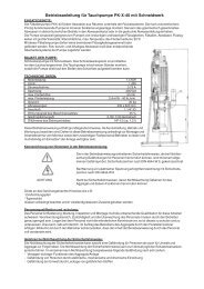
Fig. 4<br />
Wärmedehnung der <strong>Edelstahl</strong>und<br />
Kupfer-Nickel- Rohren in<br />
Abhängigkeit von der Länge<br />
und der Temperaturdierenz<br />
Thermal expansion in stainlesssteel<br />
and cupronickel as a<br />
function of the lenght and the<br />
temperature variation<br />
Für eine praktische Berechnung der Wärmedehnung in<br />
Abhängigkeit von der Änderung der Rohrlänge und des<br />
Temperatursprungs kann das Diagramm der Abbildung<br />
4 benutzt werden. Es zeigt die Kennlinien des rostfreien<br />
Stahls und der Kupfer-Nickel-Legierung und kann unter<br />
Berücksichtigung, dass die Wärmedehnung um 1/3 (-33%)<br />
geringer ist, auch für C-Stahl angewendet werden.<br />
Beispiel: Die Wärmedehnung eines 20 Meter langen<br />
rostfreien Stahlrohrs beträgt bei einer<br />
Temperaturdierenz von 70 °C:<br />
∆L = 16,5 • 20 • 70 / 1000 = 23,1 mm<br />
Dasselbe Ergebnis erhält man bei Benutzung der<br />
Abb. 4.<br />
Bei einem Rohr aus C-Stahl beträgt die<br />
Wärmedehnung:<br />
∆L = 11 • 20 • 70 / 1000 = 15,4 mm<br />
Dasselbe Ergebnis erhält man bei Benutzung<br />
der Abb. 4 und Reduzierung des für<br />
rostfreien Stahl erhaltenen Dehnungswertes um<br />
1/3 (- 7,7 mm).<br />
6.2 Dehnungsfreiraum<br />
Dehnung [mm]<br />
Expansion [mm]<br />
Bei der Rohrverlegung ist zu unterscheiden zwischen:<br />
• Freiliegende Rohrleitungen<br />
• Unterputz - Rohrverlegung<br />
• Rohrverlegung unter schwimmendem Estrich<br />
Bei freiliegenden Rohren werden die Dehnungen durch die<br />
Elastizität der Verlegungsstrecke aufgefangen, wenn die Rohre<br />
fachgerecht befestigt sind.<br />
50<br />
40<br />
30<br />
20<br />
10<br />
0<br />
0 5 10 15 20 25 30<br />
Rohrlänge [m]<br />
Pipe lenght [m]<br />
Bedienungsanleitung 8 Technical Guide<br />
PRESSFITTING SYSTEM<br />
For a practical calculation of the thermal expansion, according<br />
to the pipe length and the temperature variation, see the graph<br />
in Figure 4, which applies to stainless steel and cupronickel and is<br />
also applicable to carbon steel, but allowing for the fact that the<br />
thermal expansion of carbon steel is reduced by 1/3 (-33%).<br />
Example: The thermal expansion of a 20-metre stainless<br />
steel pipe, subjected to a temperature variation of<br />
70 °C is the following:<br />
∆L= 16.5 • 20 • 70/1000 = 23.1 mm<br />
The same result can also be obtained from the graph<br />
in g. 4.<br />
If the pipe is carbon steel, the expansion is:<br />
∆L= 11 • 20 • 70/1000 = 15.4 mm<br />
The same result can also be obtained from the graph<br />
in g. 4, but reducing the expansion for stainless steel<br />
by 1/3 (-7.7 mm).<br />
6.2 Expansion room<br />
When laying pipework, distinctions should be made between:<br />
• visible pipes<br />
• chased pipes<br />
• pipes under “ oating” oors<br />
100 °C<br />
90 °C<br />
80 °C<br />
70 °C<br />
60 °C<br />
50 °C<br />
40 °C<br />
30 °C<br />
20 °C<br />
10 °C<br />
Temperaturdierenz [°C]<br />
Temperature variation [°C]<br />
Expansion in visible pipes is absorbed by the elasticity of the run<br />
itself, provided that the pipes are correctly xed.
PRESSFITTING SYSTEM<br />
Fig. 5<br />
Unterputzverlegung<br />
Chased pipe<br />
Bei Unterputzverlegung ist wichtig, dass die Rohre nicht mit<br />
dem Verputz in Berührung kommen, sondern in elastisches<br />
Material wie Glaswolle oder Schaumsto (Abb. 5) eingebettet<br />
werden. Auf diese Weise werden gleichzeitig die Anforderungen<br />
der Schalldämmung erfüllt.<br />
Bei schwimmendem Estrich werden die Rohre unter<br />
dem Schalldämmsto verlegt und können sich daher frei<br />
ausdehnen (Abb. 6). Die vertikalen Auslässe müssen mit einer<br />
Verkleidung aus elastischem Isoliersto versehen sein. Die<br />
gleiche Vorsichtsmaßnahme muss für Rohrdurchführungen<br />
durch Wände oder Decken angewandt werden.<br />
6.3 Dehnungsausgleich<br />
Minimale Dehnungen der Rohre werden durch den<br />
Elastizitätsspielraum des Rohrleitungsnetzes aufgefangen.<br />
Falls dies nicht möglich ist, müssen Dehnungsausgleicher<br />
eingesetzt werden.<br />
Die Ausgleicher können vom U- oder Z – Typ sein, sie können<br />
vorgefertigt sein oder während der Montage mit den<br />
Komponenten des Presstting realisiert werden.<br />
Die Abb. 7 zeigt die Anordnung der U-Dehnungsausgleicher,<br />
während die Diagramme der Abb. 8 und 9 für die vorgesehene<br />
Wärmeausdehnung die Berechnung der Ausgleichslängen für<br />
<strong>Edelstahl</strong>rohre und Rohre aus Kupfer-Nickel-Legierung gestatten.<br />
Auf dieselbe Weise zeigt die Abb. 10 die Anordnung der Z-<br />
Dehnungsausgleicher, während die Diagramme der Abb.<br />
12 und 13 für die vorgesehene Wärmeausdehnung die<br />
Berechnung der Ausgleichslängen für <strong>Edelstahl</strong>rohre und<br />
Rohre aus Kupfer-Nickel-Legierung gestatten.<br />
Die letzten Diagramme sind auch für die Berechnung der<br />
Abzweigungen gültig (Abb. 11).<br />
6.4 Rohrbefestigung<br />
elastisches Material<br />
elastic bearing<br />
Die Rohrschellen haben eine doppelte Aufgabe:<br />
- die Rohre zu befestigen<br />
- die durch die Temperatursprünge verursachten<br />
Wärmedehnungen zu lenken<br />
elastisches Material<br />
elastic bearing<br />
schwimmende Sohle<br />
oating oor slob<br />
massiver Estrich<br />
massive oor<br />
Bedienungsanleitung 9 Technical Guide<br />
Chased pipes must not be in direct contact with the plaster, but<br />
wrapped in a pad of elastic material, such as glass wool or plastic<br />
foam ( g. 5). Thus tted, soundproo ng requirements are also<br />
satis ed.<br />
Under a “ oating” oor, pipes are laid below the isolation layer<br />
and can expand freely ( g. 6). Vertical channels must be coated<br />
in elastic insulating materials. The same type of coating must be<br />
applied to pipes passing through walls and ceilings.<br />
6.3 Expansion compensators<br />
Minimum pipe expansion can sometimes be compensated for by<br />
the degree of elasticity of the pipe system itself. If this is not possible,<br />
expansion compensators must be used.<br />
Compensators can be either U or Z-shaped, and can be preformed<br />
or made up when the Press tting components are being<br />
assembled.<br />
Fig. 7 shows the con guration of U-shaped compensators, while<br />
the diagrams in g. 8 and 9 allow the compensation length to be<br />
calculated, for the estimated expansion, in steel and cupronickel<br />
pipes.<br />
Similarly, g. 10 shows the con guration of a Z-shaped<br />
compensators, while the diagrams in g. 12 and 13 allow<br />
the compensation length to be calculated, for the estimated<br />
expansion, in steel and cupronickel pipes.<br />
The latter diagrams can also be used to calculate compensation<br />
in T-shaped branches ( g. 11).<br />
6.4 Pipe xing<br />
Isoliersto<br />
isolation layer<br />
The pipe support collars serve two purposes:<br />
Fig. 6<br />
Rohrleitung unter<br />
dem schwimmenden<br />
Estrich<br />
Pipe under<br />
oating oor<br />
- locking the pipe<br />
- orienting expansion caused by temperature uctuations
a<br />
b<br />
Fig. 7<br />
∆L<br />
2<br />
∆L<br />
2<br />
~ LU<br />
2<br />
30 d<br />
~ LU<br />
2<br />
U-Dehnungsausgleicher<br />
a) im präformierten Rohr<br />
b) mit Pressttings<br />
Expansion compensators U-shaped<br />
a) through preformed pipe<br />
b) with pressttings<br />
Es werden zwei Typen von Rohrschellen eingesetzt:<br />
∆L<br />
2<br />
∆L<br />
2<br />
Länge LU des U-Dehnungsausgleichers<br />
aus Kupfer-Nickel-Liegerung<br />
Lenght LU of compensator U-shaped<br />
in cupronickel<br />
- feste, die die Rohre starr an einem Punkt befestigen<br />
- gleitende Schellen, die die axiale Rohrverschiebung gestatten<br />
Anordnung der Befestigungspunkte<br />
Fig. 8<br />
Ein Rohr ohne Richtungsänderung oder ohne<br />
LU<br />
LU<br />
Fig. 9<br />
Länge LU des U-Dehnungsausgleichers aus <strong>Edelstahl</strong> und C-Stahl<br />
Bedienungsanleitung 10 Technical Guide<br />
PRESSFITTING SYSTEM<br />
Lenght LU of compensator U-shaped in stainlesssteel and carbon steel<br />
Schenkellänge LU [m]<br />
Oscillating arm LU [m]<br />
Schenkellänge LU [m]<br />
Oscillating arm LU [m]<br />
2,5<br />
2,0<br />
1,5<br />
1,0<br />
0,5<br />
0<br />
2,4<br />
2,1<br />
1,8<br />
1,5<br />
1,2<br />
0,9<br />
0,4<br />
0,3<br />
0<br />
10 20 30 40 50 60 70 80 90 100<br />
Dehnung ∆L [mm]<br />
Expansion ∆L [mm]<br />
10 20 30 40 50 60 70 80 90 100<br />
Dehnung ∆L [mm]<br />
Expansion ∆L [mm]<br />
There are two types of collars or xing points:<br />
- xed, which lock pipes rigidly<br />
- sliding, which allow axial movement<br />
Positioning xing points<br />
A pipe with no changes of direction or expansion compensators<br />
108<br />
88,9<br />
76,1<br />
54<br />
42<br />
35<br />
28<br />
22<br />
18<br />
15<br />
12<br />
54<br />
42<br />
35<br />
28<br />
22<br />
18<br />
15
PRESSFITTING SYSTEM<br />
Fig. 10<br />
Z-Dehnungsausgleicher<br />
Expansion compensators Z-shaped<br />
∆L<br />
∆L<br />
Festpunkt<br />
xed point<br />
Fig. 11<br />
T-Abzweigungen<br />
T-shaped branch<br />
LB<br />
∆L<br />
LB<br />
Gleitpunkt<br />
sliding point<br />
Fig. 13<br />
Länge LB des Z-Dehnungsausgleichers<br />
aus Kupfer-Nickel-Liegerung<br />
Lenght LB of compensator Z-shaped<br />
in cupronickel<br />
Fig. 12<br />
Dehnungsausgleicher benötigt nur einen einzigen festen<br />
Verankerungspunkt (Abb. 14). Bei langen Rohren ist es angebracht,<br />
die Schelle ungefähr in der Mitte der Strecke anzubringen,<br />
so dass die Dehnungen in beiden Richtungen unterstützt<br />
werden. Diese Lösung ist u.a. bei vertikalen Rohrverlegungen,<br />
die mehrere Stockwerke durchqueren, besonders vorteilhaft, da<br />
sie die Dehnung auf beide Richtungen verteilt und gleichzeitig<br />
auch die Beanspruchungen auf die Abzweigungen verringert.<br />
Länge LB des Z-Dehnungsausgleichers aus <strong>Edelstahl</strong> und C-Stahl<br />
Lenght LB of compensator Z-shaped in stainlesssteel and carbon steel<br />
Schenkellänge LB [m]<br />
Oscillating arm LB [m]<br />
Schenkellänge LB [m]<br />
Oscillating arm LB [m]<br />
4,5<br />
4,0<br />
3,5<br />
3,0<br />
2,5<br />
2,0<br />
1,5<br />
1,0<br />
0,5<br />
0<br />
4,5<br />
4,0<br />
3,5<br />
3,0<br />
2,5<br />
2,0<br />
1,5<br />
1,0<br />
0,5<br />
Bedienungsanleitung 11 Technical Guide<br />
10 20 30 40 50 60 70 80 90 100<br />
Dehnung ∆L [mm]<br />
Expansion ∆L [mm]<br />
0<br />
10 20 30 40 50 60 70 80 90 100<br />
Dehnung ∆L [mm]<br />
Expansion ∆L [mm]<br />
must have only one xed anchoring point ( g. 14). In the case of<br />
long pipes, we recommend placing this collar towards the centre<br />
of the section so as to allow expansion in both directions. This<br />
solution is also particularly suitable for vertical pipes that pass<br />
through many oors precisely because it allows for expansion in<br />
two directions, also decreasing stress on the branches.<br />
108<br />
88,9<br />
76,1<br />
54<br />
42<br />
35<br />
28<br />
22<br />
18<br />
15<br />
12<br />
54<br />
42<br />
35<br />
28<br />
22<br />
18<br />
15
Außerdem dürfen keine starren Befestigungspunkte in Höhe<br />
der Fittings angebracht werden (Abb. 15); ebenso müssen die<br />
gleitenden Befestigungen so angeordnet werden, dass sie<br />
nicht zu gefährlichen starren Befestigungspunkten werden<br />
können (Abb. 16).<br />
Mindestabstände<br />
Fig. 14<br />
Rohrbefestigung:<br />
gerade Rohr, nur ein<br />
Festpunkt: korrekt<br />
Pipe xing: straight pipe,<br />
only one xed point: suitable<br />
Fig. 16<br />
Rohrbefestigung:<br />
Gleitpunkt nah vom<br />
Fitting<br />
Pipe xing: sliding point<br />
near to tting: wrong<br />
Für eine fachmännische Verlegung der Rohre müssen einige<br />
Mindestabstände eingehalten werden, die von verschiedenen<br />
Faktoren abhängen:<br />
• Abstand zwischen den Befestigungspunkten<br />
Die Befestigungspunkte müssen in geeigneten Abständen<br />
angeordnet werden. Zu nahe beieinander liegende<br />
Befestigungen können den Dehnungsausgleich verhindern,<br />
während zu weit auseinander liegende Befestigungen die<br />
Vibrationen verstärken und damit störende Geräusche<br />
verursachen können. Die vom Hersteller empfohlenen<br />
Abstände sind in der Tabelle 2 ersichtlich<br />
• Bewegungsfreiheit für die Presswerkzeuge.<br />
Um Schwierigkeiten während des Verpressens zu vermeiden,<br />
ist ausreichender Bewegungsfreiraum einzuplanen, der von<br />
den Abmessungen der jeweiligen System – Dimension<br />
und dem Presswerkzeug abhängt. Tabelle 3 zeigt die<br />
erforderlichen Mindestfreiräume.<br />
Fig. 15<br />
Bedienungsanleitung 12 Technical Guide<br />
PRESSFITTING SYSTEM<br />
Rohrbefestigung: Festpunkt auf dem Fitting: falsch<br />
Pipe xing: xed point on tting: wrong<br />
Ø Rohr / pipe 12 15 18 22 28 35 42 54 76,1 88,9 108<br />
Abstand (m)<br />
Distance (m)<br />
Festpunkt<br />
korrekt<br />
xed point suitable<br />
Festpunkt<br />
xed point<br />
Festpunkt<br />
xed point<br />
1,<br />
5<br />
korrekt<br />
suitable<br />
Tab. 2 Mindestabstände zwischen den Befestigungspunkten Minimum distances between xing points<br />
2,<br />
5<br />
NO<br />
3,<br />
5<br />
NO<br />
korrekt<br />
suitable<br />
Fixed collars must not be placed on ttings ( g. 15) and even<br />
sliding collars must be positioned so as not to foul ttings and<br />
become potentially dangerous xed points ( g. 16).<br />
Minimum distances<br />
Installing pipework correctly involves observing certain minimum<br />
distances, which depend on several dierent factors:<br />
• Distance between xing points<br />
Fixing points must be placed at an adequate distance from each<br />
other. If the brackets are too close together they can prevent<br />
the absorption of expansion. If they are too far apart they can<br />
increase vibration and amplify noise. Tab. 2 shows the distances<br />
recommended by the producer.<br />
• Manoeuvring space for the pressing tool<br />
Adequate space for manoeuvre and avoid obstacles must be<br />
allowed and this will vary according to the size of the pressing<br />
tool. Tab. 3 shows the minimum space to be allowed.<br />
5
PRESSFITTING SYSTEM<br />
Tab. 4<br />
Mindestabstände<br />
zwischen den Fittings<br />
Minimum distances<br />
between ttings<br />
Tab. 3<br />
Mindestfreiräume für<br />
die Verpressung<br />
Minimum pressing<br />
spaces<br />
Ø Rohr / pipe 15 18 22 28 35 42 54 76,1 88,9 108<br />
A (mm) 25 27 35 35 45 76 86 190 210 210<br />
B (mm) 75 81 81 81 85 120 125 200 250 250<br />
C (mm) 56 60 76 76 76 120 125 200 250 250<br />
L (mm) 24 24 32 32 32 78 88 170 170 170<br />
• Abstand zwischen den Fittings<br />
Zwei Verpressungen in unmittelbarer Nähe können die<br />
Dichtheit der Rohrverbindungen beeinträchtigen. In der<br />
Tabelle 4 sind die Mindestabstände ersichtlich.<br />
7. INSTALLATIONSANWEISUNGEN<br />
7.1 Transport und Lagerung<br />
d min<br />
Die Rohre werden für die Lieferung an den Enden mit Kappen<br />
verschlossen, die das Eindringen von Schmutz verhindern. Die<br />
Rohrreste, die noch verwendbar sind, sollten bis zur späteren<br />
Verwendung wieder verschlossen werden.<br />
C C B A<br />
Ø Rohr / pipe d min (mm)<br />
12-15 20<br />
18 25<br />
22-28 30<br />
35 35<br />
42 40<br />
54 45<br />
76,1 55<br />
88,9 65<br />
108 80<br />
Bedienungsanleitung 13 Technical Guide<br />
• Distance between ttings<br />
Two press ttings too close together can compromise the<br />
perfect seal of the joints. Tab. 4 shows the minimum distances to<br />
observe.<br />
7. INSTALLATION INSTRUCTIONS<br />
7.1 Transport and storage<br />
The pipes are supplied with plastic plugs at either end to keep out<br />
dirt. These plugs should be replaced to protect leftover pipes for<br />
later use.<br />
L
Fig. 17<br />
Zuschneiden der Rohre<br />
Pipe cutting<br />
7.2 Zuschneiden der Rohre (Abb. 17)<br />
Die Rohre müssen mit einem Rohrschneider oder mit einer<br />
Säge mit feinen Zähnen geschnitten werden.<br />
Es dürfen keine Werkzeuge benutzt werden, bei denen die<br />
Gefahr von Verformung oder durch Überhitzung besteht, wie<br />
Schweißbrenner oder Schleifscheiben.<br />
7.3 Entgraten der Rohrenden (Abb. 18)<br />
Nach dem Zuschnitt müssen die Rohre sorgfältig außen und<br />
innen mit einem manuellen oder elektrischen Abgratwerkzeug<br />
entgratet werden, um zu vermeiden, dass der Dichtring beim<br />
Einsetzen der Rohre in die Fittings beschädigt wird und<br />
dadurch Druckverluste auftreten können. Außerdem müssen<br />
alle Schnittreste (Späne) entfernt werden.<br />
7.4 Kontrolle des Sitzes der O-Ringe (Abb. 19)<br />
Vor der Montage der Fittings muss der Sitz der Dichtungsringe<br />
im Fitting überprüft werden. Die O-Ringe können mit Wasser<br />
oder Talk benutzt werden, um das Einsetzen des Rohrs zu<br />
erleichtern.<br />
Die Verwendung von Öl, Fett, Klebern oder ähnlicher Stoe als<br />
Gleitmittel ist strikt untersagt.<br />
7.5 Einsetzen der Rohre in die Fittings und<br />
Kennzeichnung (Abb. 20)<br />
Fig. 18<br />
Entgraten der Rohrenden<br />
Pipe-end deburring<br />
Das Rohr wird mit einer leichten Drehung bis zum Anschlag<br />
in den Fitting eingeschoben. Außerdem muss für eine<br />
fachmännische und sichere Verbindung mit einem Filzstift auf<br />
dem Rohr die erreichte Einsteck - Tiefe markiert werden, um<br />
eventuelle Verschiebungen vor oder während des Verpressens<br />
feststellen zu können.<br />
7.2 Pipe cutting ( g. 17)<br />
Bedienungsanleitung 14 Technical Guide<br />
Fig. 19<br />
PRESSFITTING SYSTEM<br />
Pipes must be cut at right angles to their axis, using a pipe cutter<br />
or ne-tooth saw, taking into account the depth of insertion into<br />
the tting.<br />
Avoid equipment that may cause heat deformation such as<br />
blowtorches or grinding wheels.<br />
7.3 Pipe-end deburring ( g. 18)<br />
Kontrolle des Sitzes der O-Ringe<br />
Checking o-ring positioning<br />
After cutting, the pipe must be carefully deburred, both inside and<br />
outside, using a manual or electric deburring tool so as to avoid<br />
damaging the o-ring gasket when the pipe is inserted into the<br />
tting, causing possible leaks. Any cutting residue (shavings) must<br />
be removed.<br />
7.4 Checking o-ring positioning ( g. 19)<br />
Before assembling the ttings, the positioning of the o-rings in<br />
their toroidal seats must be checked and, if necessary, lubricated<br />
with water or talc to ease the insertion of the pipe.<br />
Oils, greases, glues or other similar substances must on no account<br />
be used.<br />
7.5 Inserting pipes in ttings and marking ( g. 20)<br />
The pipe is inserted in the tting with a slight rotating motion until<br />
it hits the stop.<br />
To produce a perfectly secure joint, the pipe must be marked with a<br />
felt-tip pen where it meets the tting so that any movement before<br />
or after pressing can be identi ed.
PRESSFITTING SYSTEM<br />
Fig. 20<br />
Einsetzen der Rohre in die Fittings und Kennzeichnung<br />
Inserting pipe in ttigs and marking<br />
Fig. 21<br />
Verwendung des Rohrschraubstocks für Durchmesser “Big Size”<br />
Use of assemblyclamps for Big Sizes diameters<br />
7.6 Verwendung des Rohrschraubstocks für<br />
Durchmesser “Big Size” (Abb. 21)<br />
Bei großen Durchmessern (76,1-88,9-108 mm) ist es<br />
angebracht, die Rohre und Fittings vor dem Verpressen mit<br />
einem Rohrschraubstock zu blockieren, um die Koaxialität zu<br />
gewährleisten.<br />
7.7 Bestückung der Presswerkzeuge (Abb. 22 e 23)<br />
Die Presswerkzeuge müssen mit Pressbacken mit „M“-Kontur<br />
bestückt werden, die dem Durchmesser der eingesetzten<br />
Verbindung entspricht. Halten Sie sich bei der Bestückung an<br />
die Gebrauchsanweisungen des spezi schen Werkzeugs.<br />
7.8 Verpressen (Abb. 24 e 25)<br />
Für zuverlässiges und sicheres Verpressen muss die Innennut<br />
der Pressbacken perfekt die ringförmige Wulst der Dichtung<br />
der Fittings umspannen.<br />
Fig. 22 - 23<br />
Bedienungsanleitung 15 Technical Guide<br />
Bestückung der Presswerkzeuge<br />
Pressing tool assembly<br />
Fig. 24 - 25<br />
Verpressen<br />
Pressing<br />
7.7 Use of assembly clamps for “Big Size” diameters<br />
( g. 21)<br />
When pressing “Big Size” diameters (76.1, 88.9, 108 mm), it is<br />
advisable to secure the pipes with an assembly clamp to ensure<br />
the correct alignment.<br />
7.6 Pressing tool assembly ( g. 22 and 23)<br />
The pressing tools must be equipped with M-shaped pro les jaw<br />
attachments corresponding to the diameter of the tting to be<br />
inserted. Refer to the user manual for the particular tool for set-up<br />
and operating instructions.<br />
7.8 Pressing ( g. 24 and 25)<br />
For a good, reliable press tting, the internal channel of the jaws<br />
must form a perfect t round the toroidal seat of the tting.
Das Verpressen erfolgt durch Schließen der Pressbacken.<br />
Doppeltes Verpressen ist unzulässig, da dadurch die Dichtheit<br />
beeinträchtigt wird.<br />
8. KORROSIONSBESTÄNDIGKEIT<br />
8.1 Trinkwasser-Installationen aus rostfreiem Stahl<br />
Interne Rostbeständigkeit<br />
Die Trinkwassereigenschaften werden durch rostfreien<br />
Stahl nicht verändert, der seinerseits keine Änderungen<br />
erfährt. Trinkwasser und behandeltes Wasser sind daher voll<br />
kompatibel mit dem vom Hersteller eingesetzten rostfreien<br />
Stahl AISI 316L. Dadurch ist absolute Hygiene gewährleistet.<br />
Bimetallische Rostbeständigkeit<br />
Der rostfreie Stahl bewahrt seine korrosionsbeständigen<br />
Eigenschaften auch bei Einsatz in Verbindung mit<br />
Nichteisenmetallen (Bronze, Kupfer, Messing) mit Ausnahme<br />
von C-Stahl, bei dem bimetallische Rosterscheinungen<br />
auftreten können, wenn die beiden Metalle in direkte<br />
Berührung kommen. Diese Erscheinung kann durch Einsetzen<br />
einer nichteisenhaltigen Schicht zwischen den beiden Metallen<br />
verringert oder durch Verwendung von nichteisenhaltigen<br />
Abstandhaltern mit Mindestlänge von 50 mm völlig beseitigt<br />
werden.<br />
Äußere Rostbeständigkeit<br />
Die äußere Korrosion einer Anlage aus rostfreiem Stahl<br />
dürfte nur unter ganz besonders ungünstigen Bedingungen<br />
auftreten, wie bei längerer Aussetzung in Elementen mit hoher<br />
Chloridkonzentration. In diesen Fällen ist es angebracht, die<br />
Rohre mit geschlossenzelligen Mänteln zu schützen, wobei<br />
darauf zu achten ist, dass ganz besonders die Rohrschnitt-<br />
und die Verbindungspunkte abzudichten sind. Alternativ<br />
können Rostschutzisolierbänder verwendet werden, während<br />
Filzmäntel auf keinen Fall benutzt werden dürfen, da diese<br />
Feuchtigkeit auf lange Zeit zurückhalten und dadurch die<br />
Entstehung von Rost fördern.<br />
8.2 C-Stahlinstallationen für Heizungsanlagen<br />
Interne Rostbeständigkeit<br />
In Heizungsanlagen mit geschlossenem Wasserkreislauf<br />
kann Sauersto gewöhnlich nicht von außen eindringen; die<br />
Rohrleitungen aus C-Stahl sind daher keiner inneren Korrosion<br />
ausgesetzt. Die Komponenten aus C-Stahl können außerdem<br />
auch in gemischten Anlagen verwendet werden, in denen<br />
auch nichteisenhaltige Metalle wie Kupfer, Aluminium usw.<br />
eingesetzt werden.<br />
Bedienungsanleitung 16 Technical Guide<br />
PRESSFITTING SYSTEM<br />
The joint is pressed by closing the jaws. Pressing must only be<br />
carried out once, otherwise the seal could be damaged. Some<br />
swelling, occurring in the area outside the toroidal seat, can be<br />
considered normal.<br />
8. CORROSION RESISTANCE<br />
8.1 Stainless steel installations for drinking water<br />
Resistance to internal corrosion<br />
Stainless steel does not change the characteristics of drinking<br />
water, nor does the water aect it in any way. For this reason,<br />
drinking water, even when treated, is absolutely compatible with<br />
the AISI 316L stainless steel used by the producer.<br />
Perfect hygiene is thus guaranteed.<br />
Resistance to bimetallic corrosion<br />
Stainless steel is resistant to corrosion, even in systems where it<br />
is<br />
in<br />
contact<br />
with<br />
non-fer<br />
rous<br />
metals<br />
( bronze<br />
, coppe<br />
r and<br />
brass)<br />
.<br />
If however, it is in direct contact with carbon steel, bimetallic<br />
corrosion can occur. This risk can be reduced by inserting a nonferrous<br />
joint between the two metals or it can be completely<br />
eliminated by using non-ferrous spacers at least 50mm in length<br />
Resistance to external corrosion<br />
External corrosion can only occur on a stainless steel system<br />
in very particular situations, such as prolonged contact with<br />
high concentrations of chlorides. In these cases, we recommend<br />
covering the pipes with a closed-cell coating, taking care to apply<br />
waterproof glue to the cutting and junction points. Alternatively,<br />
protective anti-corrosion tape can be used. Felt sheathing must<br />
not be used as it holds moisture that can lead to corrosion.<br />
8.2 Carbon steel installations for heating<br />
Resistance to internal corrosion<br />
Oxygen is not normally able to penetrate closed-circuit water<br />
heating systems from the outside so carbon steel pipes are not<br />
subject to internal corrosion. Carbon steel components can also<br />
be used in mixed installations with other non-ferrous metals, such<br />
as copper, aluminium, etc.
PRESSFITTING SYSTEM<br />
Die Anlagen müssen auf jeden Fall immer komplett gefüllt<br />
oder während des Stillstands vollständig entleert und trocken<br />
sein, um das gleichzeitige Vorhandensein von Wasser, Luft und<br />
Metall zu vermeiden, die die Grundlagen für Korrosion sind.<br />
Äußere Rostbeständigkeit<br />
Äußere Korrosion einer Anlage aus C-Stahl kann sich leicht bei<br />
Unterputzverlegung der Rohre und bei hoher Feuchtigkeit<br />
einstellen. In diesem Fall ist es angebracht, die Rohre mit<br />
geschlossenzelligen Mänteln oder Isolierschutzbänder<br />
zu schützen, wobei darauf zu achten ist, dass keine Teile<br />
unbedeckt bleiben.<br />
Auf keinen Fall dürfen Filzmäntel benutzt werden, da diese<br />
Feuchtigkeit auf lange Zeit zurückhalten und dadurch die<br />
Entstehung von Rost fördern.<br />
9. SONSTIGE VORSCHRIFTEN<br />
9.1 Dichtheitsprüfung<br />
Nach Abschluss der Installation muss die Anlage auf Dichtheit<br />
geprüft werden.<br />
Für Trinkwasser- und Heizungsanlagen ist die vorschriftsmässige<br />
Prüfung mit Wasser bei einem Druck auszuführen, der<br />
mindestens 1,5 Mal dem Betriebsdruck entspricht.<br />
Wenn während der Prüfung keine Verluste festzustellen sind,<br />
ist die Rohrleitung vor dem Befüllen der Anlage energisch zu<br />
spülen.<br />
Bei Gasanlagen ist die Prüfung mit Luft / Inertgas mit einem<br />
Mindestdruck von 10 bar auszuführen.<br />
9.2 Schallisolierung<br />
Leitungs – System können Schall übertragen, der von anderen<br />
Quellen (<strong>Pumpen</strong>, Ventilen usw.) erzeugt wird und müssen<br />
daher entsprechend durch elastisches Material isoliert werden,<br />
das ihren direkten Kontakt mit Schellen, Mauerwerk usw.<br />
verhindert.<br />
9.3 Wärmedämmung<br />
Warmwasserleitungen müssen laut Bestimmungen zur<br />
Energieeinsparung und Vorschriften für Heizungsanlagen isoliert<br />
werden. Auf diese Weise werden auch die Sicherheitsvorschriften<br />
hinsichtlich des Berührungsschutzes erfüllt.<br />
Kaltwasserleitungen müssen zur Vermeidung von<br />
Kondenswasserbildung mit dem daraus folgende Abtropfen<br />
von Wasser ebenfalls entsprechend isoliert werden. Bei<br />
<strong>Edelstahl</strong> – Systemen ist die Verwendung von chloridhaltigen<br />
Isoliermaterialien nicht zulässig.<br />
Bedienungsanleitung 17 Technical Guide<br />
However, such systems must always be kept lled, even when not<br />
operating, or should be emptied and kept dry, to avoid both air<br />
and water being in contact with the metal, a situation that can<br />
lead to corrosion.<br />
Resistance to external corrosion<br />
External corrosion can frequently occur on carbon steel systems<br />
in chased installations, in humid conditions. To prevent this,<br />
we recommend covering the pipes with closed-cell coating or<br />
protective anti-corrosion tape, ensuring that the pipes are entirely<br />
covered.<br />
Felt sheathing must not be used as it holds moisture that can lead<br />
to corrosion.<br />
9. GENERAL REQUIREMENTS<br />
9.1 Seal testing<br />
Once the system is installed, it must be tested for leaks.<br />
Drinking water or heating installations are tested using water at a<br />
pressure at least 1.5 times the operating pressure.<br />
If no leaks are detected during testing, it is advisable to clean the<br />
pipes thoroughly before charging the system with water.<br />
Gas systems are tested with air/inert gas at a minimum pressure<br />
of 10 bar.<br />
9.2 Noise insulation<br />
Pipes are a possible means of transmitting noise from other sources<br />
(pumps, valves, etc.) and, for this reason, they must be insulated<br />
with elastic materials to avoid direct contact with collars, walls,<br />
etc.<br />
9.3 Thermal insulation<br />
Hot water pipes must be insulated in compliance with the codes of<br />
practice relating to energy conservation and heating systems.<br />
This also acts as a safety precaution against accidental contact.<br />
Cold water pipes must also be adequately insulated to prevent<br />
condensation and dripping. For stainless steel installations the<br />
insulating material has to be without chlorine or its compounds.
9.4 Frostschutz<br />
Falls Gefahr besteht, dass das Wasser in den Leitungen gefrieren<br />
kann, müssen die Rohre mit geeignetem Material in passender<br />
Stärke oder durch Zusätze von Frostschutzmitteln zum Wasser<br />
geschützt werden, um zu verhindern, dass die Rohre platzen<br />
oder undicht werden.<br />
10. GARANTIE<br />
Der Einsatz der originalen Press ttings in Verbindung mit<br />
geprüften und zugelassenen Rohren und unter Einsatz<br />
freigegebener Presswerkzeuge und unter gewissenhafter<br />
Einhaltung der technischen Anweisungen sowohl während<br />
der Planung als auch bei der Installation der Anlagen<br />
gewährleisten eine lange Lebensdauer des Systems.<br />
Bedienungsanleitung 18 Technical Guide<br />
9.4 Protection against freezing<br />
PRESSFITTING SYSTEM<br />
Where there is a danger of water freezing in pipes, they must<br />
be protected with insulating material of suf cient thickness or<br />
antifreeze should be used to avoid leaks caused by loosened joints<br />
or swelling.<br />
10. GUARANTEE<br />
The use of original Press ttings, with the correct pipes and<br />
approved pressing tools, coupled with strict adherence to the<br />
technical instructions given for both the design and installation of<br />
the system, will guarantee the longevity of the system.
PRESSFITTING SYSTEM<br />
11. TABELLEN DER FITTINGSVERBINDUNG 11. COUPLING FITTINGS TABLE<br />
MINDESTABSTÄNDE ZWISCHEN ZWEI VERPRESSUNGEN DOPPEL T-STÜCK NEBENEINANDERTE<br />
T-STÜCKE<br />
MINIMUM DISTANCE BETWEEN TWO PRESSES DUBLE<br />
TEE<br />
SIDE<br />
MOUNTED<br />
TEES<br />
DN d L-min A-min e DN H L-min X-min Z DN H L-min X-min Z1<br />
12 20 46 10 18 12 97 46 80 17 12 122 46 82 18<br />
15 23 52 10 21 15 103 52 83 16 15 158 52 93 21<br />
18 26 52 10 21 18 108 52 85 17 18 169 52 92,5 20<br />
22 32 56 10 23 22 123 56 96 20 22 178 56 104 24<br />
28 37 58 10 24 28 135 58 102 22 28 194 58 106 24<br />
35 44 64 10 27 35 161 64 121 29 35 213 64 116,5 26<br />
42 54 84 20 32 42 187 84 140 28 42 256 84 148 32<br />
54 65 94 20 37 54 225 94 166 36 54 304 94 168 37<br />
76 96 130 20 55 76 333 130 252 61 76 484 130 240 55<br />
88 110 146 20 63 88 365 146 272 63 88 544 146 272 63<br />
108 133 176 20 78 108 437 176 324 74 108 644 176 332 78<br />
BOGEN 45°<br />
I/<br />
I MIT<br />
BOGEN<br />
45°<br />
I/<br />
A<br />
2 BÖGEN<br />
45°<br />
I/<br />
I MIT<br />
ROHR BOGEN 90° I/I MIT BOGEN 90° I/A<br />
ELBOW 45°<br />
FF<br />
WITH<br />
ELBOW<br />
45°<br />
MF<br />
2 ELBOWS<br />
45°<br />
FF<br />
WITH<br />
PIPE ELBOW 90°FF WITH ELBOW 90°MF<br />
DN A Z Z1 Z2 B DN L-min A-min Z-min Z DN A H Z Z1<br />
Radius 1,<br />
5<br />
Radius<br />
1,<br />
5<br />
Radius<br />
1,5<br />
15 45 77 16 16 45 15 52 59 91 16 15 83 56 54 27<br />
18 44 78 17 17 44 18 52 61 95 17 18 94 62 64 32<br />
22 52 94 21 21 52 22 56 69 111 21 22 105 68 74 37<br />
28 62 116 27 27 62 28 58 79 133 27 28 127 80 94 47<br />
35 69 133 32 32 69 35 64 91 155 32 35 154 93 122 61<br />
42 88 178 45 45 88 42 84 123 213 45 42 208 125 166 83<br />
54 105 207 51 51 105 54 94 139 241 51 54 255 149 212 106<br />
Radius 1,<br />
2<br />
Radius<br />
1,<br />
2<br />
Radius<br />
1,2<br />
12 39 67 14 14 39 12 46 52 80 14 12 72 48 48 24<br />
15 36 54 10 10 34 15 52 49 67 9 15 69 49 40 20<br />
18 32 52 11 11 30 18 52 51 71 10 18 77 53 48 24<br />
22 42 66 13 13 40 22 56 57 81 12 22 85 59 52 26<br />
28 45 79 17 17 45 28 58 65 99 17 28 104 69 70 35<br />
35 67 125 29 29 67 35 64 86 144 29 35 128 83 90 45<br />
42 71 133 32 32 69 42 84 103 165 31 42 155 96 118 59<br />
54 85 161 40 40 81 54 94 120 196 38 54 189 116 146 73<br />
76 115 201 43 43 115 76 130 153 239 43 76 261 166 190 95<br />
88 127 227 50 50 127 88 146 174 274 50 88 301 190 222 111<br />
108 156 276 62 62 152 108 176 209 329 60 108 367 230 274 137<br />
Bedienungsanleitung 19 Technical Guide
Bedienungsanleitung 20 Technical Guide<br />
PRESSFITTING SYSTEM<br />
2 BÖGEN 90° I/I MIT ROHR BOGEN 90° I/I MIT PASSBOGEN 90° (lange Seite) BOGEN 90° I/I MIT PASSBOGEN (kurze Seite)<br />
2 ELBOWS 90°FF WITH PIPE ELBOW 90°FF AND ELBOW WITH PLAIN ENDS 90° (long side) ELBOW 90°FF AND ELBOW WITH PLAIN ENDS 90° (short side)<br />
DN A-min L-min Z Z1 DN A-min Z1 Z H h DN A-min Z1 Z H h<br />
Radius 1,<br />
5<br />
Radius<br />
1,<br />
5<br />
Radius<br />
1,5<br />
15 52 114 54 27 15 147 27 97 70 48 15 97 27 147 120 48<br />
18 52 114 64 32 18 152 32 102 70 53 18 102 32 152 120 53<br />
22 56 122 74 37 22 157 37 107 70 61 22 107 37 157 120 61<br />
28 58 126 94 47 28 172 47 144 97 90 28 144 47 172 125 78<br />
35 64 138 122 61 35 262 61 182 121 59 35 182 61 262 201 139<br />
42 84 188 166 83 42 337 83 243 160 70 42 243 83 337 254 164<br />
54 94 208 212 106 54 408 106 308 202 157 54 308 106 408 302 257<br />
Radius 1,<br />
2<br />
Radius<br />
1,<br />
2<br />
Radius<br />
1,2<br />
12 46 102 48 24 12 144 24 94 70 53 12 94 24 144 120 53<br />
15 52 114 40 20 15 140 20 90 70 48 15 90 20 140 120 48<br />
18 52 114 48 24 18 144 24 94 70 53 18 94 24 144 120 53<br />
22 56 122 52 26 22 146 26 96 70 61 22 96 26 146 120 61<br />
28 58 126 70 35 28 160 35 132 97 90 28 132 35 160 125 78<br />
35 64 138 90 45 35 246 45 166 121 59 35 166 45 246 201 139<br />
42 84 188 118 59 42 313 59 219 160 70 42 219 59 313 254 164<br />
54 94 208 146 73 54 375 73 275 202 157 54 275 73 375 302 257<br />
76 130 280 190 95 76 345 95 345 250 190 76 345 95 345 250 190<br />
88 146 312 222 111 88 402 111 402 291 201 88 402 111 402 291 201<br />
108 176 372 274 137 108 501 137 501 364 319 108 501 137 501 364 319<br />
BOGEN 45° I/A MIT SEITLICHEM T-STÜCK BOGEN 45° I/A MIT SEITLICHEM T-STÜCK UND ROHR BOGEN 45° I/A UND SEITLICHER BOGEN 90° I/I<br />
ELBOW 45°MF WITH LATERAL TEE ELBOW 45°MF WITH LATERAL TEE AND PIPE ELBOW 45°MF AND LATERAL ELBOW 90°FF<br />
DN Z A D Z1 Z2 DN A B L-min Z1 Z2 DN Z A B Z1 Z2<br />
Radius 1,<br />
5<br />
Radius<br />
1,<br />
5<br />
Radius<br />
1,5<br />
15 60 44 44 16 16 15 59 59 52 16 16 15 60 44 44 27 16<br />
18 60 43 43 17 17 18 60 60 52 17 17 18 60 43 43 32 17<br />
22 72 51 51 21 20 22 69 69 56 21 20 22 72 51 51 37 21<br />
28 85 58 58 27 22 28 76 76 58 27 22 28 85 58 58 47 27<br />
35 98 66 66 32 29 35 88 88 64 32 29 35 98 66 66 61 32<br />
42 121 76 76 45 28 42 111 111 84 45 28 42 121 76 76 83 45<br />
54 145 94 94 51 36 54 128 128 94 51 36 54 145 94 94 106 51<br />
Radius 1,<br />
2<br />
Radius<br />
1,<br />
2<br />
Radius<br />
1,2<br />
12 55 41 41 14 17 12 54 54 46 14 17 12 55 41 41 24 14<br />
15 49 40 40 9 16 15 54 54 52 9 16 15 49 40 40 20 9<br />
18 46 36 36 10 17 18 56 56 52 10 17 18 46 36 36 24 10<br />
22 59 47 47 12 20 22 62 62 56 12 20 22 59 47 47 26 12<br />
28 66 49 49 17 22 28 69 69 58 17 22 28 66 49 49 35 17<br />
35 95 66 66 29 29 35 86 86 64 29 29 35 95 66 66 45 29<br />
42 100 69 69 31 28 42 101 101 84 31 28 42 100 69 69 59 31<br />
54 121 83 83 38 36 54 119 119 94 38 36 54 121 83 83 73 38<br />
76 174 131 131 43 61 76 165 165 130 43 61 76 174 131 131 95 43<br />
88 186 136 136 50 63 88 183 183 146 50 63 88 186 136 136 111 50<br />
108 225 165 165 60 74 108 219 219 176 60 74 108 225 165 165 137 60
PRESSFITTING SYSTEM<br />
BOGEN 90° I/A MIT SEITLICHEM T-STÜCK BOGEN 90° I/I MIT SEITLICHEM T-STÜCK UND ROHR SEITLICHER BOGEN 90° I/I UND ROHR<br />
ELBOW 90°MF WITH LATERAL TEE ELBOW 90°MF WITH LATERAL TEE AND PIPE LATERAL ELBOW 90°FF AND PIPE<br />
DN M h Z1 Z2 DN M-min L-min Z1 Z2 DN A-min B-min L-min Z1 Z2<br />
Radius 1,<br />
5<br />
Radius<br />
1,<br />
5<br />
Radius<br />
1,5<br />
15 71 55 27 16 15 94 52 27 16 15 67 67 52 27 16<br />
18 78 62 32 17 18 100 52 32 17 18 71 71 52 32 17<br />
22 88 68 37 20 22 113 56 37 20 22 81 81 56 37 21<br />
28 102 80 47 22 28 127 58 47 22 28 93 93 58 47 27<br />
35 121 93 61 29 35 153 64 61 29 35 111 111 64 61 32<br />
42 153 125 83 28 42 195 94 83 28 42 150 150 84 83 45<br />
54 185 149 106 36 54 236 104 106 36 54 178 178 94 106 51<br />
Radius 1,<br />
2<br />
Radius<br />
1,<br />
2<br />
Radius<br />
1,2<br />
12 65 48 24 17 12 87 46 24 17 12 59 59 46 24 14<br />
15 64 48 20 16 15 87 52 20 16 15 57 57 52 20 9<br />
18 69 53 24 17 18 92 52 24 17 18 61 61 52 24 10<br />
22 79 59 26 20 22 102 56 26 20 22 66 66 56 26 12<br />
28 91 69 35 22 28 115 58 35 22 28 78 78 58 35 17<br />
35 111 83 45 29 35 137 64 45 29 35 98 98 64 45 29<br />
42 124 96 59 28 42 161 94 59 28 42 123 123 84 59 31<br />
54 152 116 73 36 54 203 104 73 36 54 145 145 94 73 38<br />
76 232 171 95 61 76 291 140 95 61 76 190 190 130 95 43<br />
88 253 190 111 63 88 320 156 111 63 88 217 217 146 111 50<br />
108 304 230 137 74 108 387 186 137 74 108 264 264 176 137 60<br />
Bedienungsanleitung 21 Technical Guide<br />
T-STÜCK MIT REDUZIER-STÜCK<br />
TEE AND REDUCTION<br />
DN L2 L1 Z Z1 DN L2 L1 Z Z1<br />
15-12 49 37 33 16 42-22 82 59 55 27<br />
18-12 54 40 35 19 42-28 104 59 77 27<br />
18-15 56 40 37 19 42-35 74 59 47 27<br />
22-12 61 42 42 19 54-18 121 71 87 34<br />
22-15 61 42 42 19 54-22 122 71 88 34<br />
22-18 60 42 41 19 54-28 109 71 75 34<br />
28-12 79 46 57 22 54-35 135 71 101 34<br />
28-15 83 46 61 22 54-42 112 71 78 34<br />
28-18 86 46 64 22 76,1-42 182 116 121 61<br />
28-22 67 46 45 22 76,1-54 170 116 109 61<br />
35-15 88 51 64 24 88,9-54 190 131 122 68<br />
35-18 91 51 67 24 88,9-76,1 173 131 105 68<br />
35-22 78 51 54 24 108-54 245 156 167 78<br />
35-28 73 51 49 24 108-76,1 222 156 144 78<br />
42-18 101 59 74 27 108-88,9 211 156 133 78
Die Tabelle hat eine allgemeine Gueltigkeit. Wenden Sie sich bitte an unserem Technischen Buero, um weitere Info zu kriegen.<br />
12. CHEMISCHE VERTRÄGLICHKEIT DER ROHRE UND DICHTUNGEN *<br />
FLÜSSIGKEIT<br />
ROHR DICHTUNGEN<br />
AISI 316L<br />
C-STAHL<br />
EPDM<br />
HNBR<br />
FKM<br />
NBR<br />
Bedienungsanleitung 22 Technical Guide<br />
FLÜSSIGKEIT<br />
PRESSFITTING SYSTEM<br />
ROHR DICHTUNGEN<br />
(Handels-) Acetylen A - A - A A Fluorwasserstoff - - - - - -<br />
Acetum A - A D A D<br />
Formaldehyd<br />
A - A - B A<br />
Aceton 100% - 100°C A - A - D D Ammoniumsalz von Phosphatidsäure 10% C - A - A A<br />
Essigsäure 20%<br />
A -<br />
C - C C Natriumphosphat C - A - A A<br />
Borsäure 5%<br />
A - A - A A<br />
Kokereigas<br />
A - D A A A<br />
Zitronensäure 5% A - A - A A Gasöl A - D A A A<br />
Ameisensäure C - B - D D Glyzerin A - A - B A<br />
Phosphorsäure 5% A - A - A C Glykol<br />
A - A A A A<br />
Chlorwasserstosäure D - B - D C Äthylglykol A - A A A A<br />
Salpetersäure 30% - 80°C A - D D D D Calciumhydroxid 10°C - 100% C - A - A A<br />
Ölsäure A - D - A B Magnesiumhydroxid ≤ 10%-100°C C - A - A A<br />
Säure für Batterien A - A - A C Kaliumhydroxid ≤50°C C - A - C C<br />
Blausäure 100% C - C - A C Calciumhypochlorid 100% - - A - A D<br />
Schwefelsäure 10% - 60°C D D A - C C Milch A D A - A A<br />
Schwefelsäure - Dampf D D D - A D Methan A A D A A A<br />
Schwefelsäure 100% C D D - B D Methanol A D A D B C<br />
Weinsäure 10% - 100°C A - - - - - Treiböl A - D A A A<br />
Wasser 100°C A A A A A A Naphthalin A D D - A C<br />
Meerwasser A D A - A A<br />
Ammoniumnitrat<br />
10-50% A - A - A C<br />
destilliertes Wasser 50°C A - A - B B Kupfernitrat - - A - A B<br />
Königswasser A - C - B D Natriumnitrat 10% - 40% A - A - A A<br />
Agenzien für Zurichtung von Leder A - A A A A Lebertran A D B - A A<br />
Äthylalkohol 100% A - A - B B Rizinsöl A D D - A A<br />
Methylalkohol 100% A D A D A C Leinöl A - D - A A<br />
Ammoniak 100% A - B - C C Olivenöl A D D A A A<br />
Anilin 100%<br />
A -<br />
C - A D Schmieröl A A D - A A<br />
Druckluft A - D A A A Maschinenöl A B D - A A<br />
Chrombeize A - A A A A Mineralöl A A D - A A<br />
Benzol A - D - C D Motorenöl A A D - A A<br />
Benzin A - D - A A Getriebeöl A - D A A A<br />
Natriumbicarbonat A - A - A B P anzenöl A D D A A A<br />
Bier A - A - A A<br />
Parafn A - D - A A<br />
Butan A - D B B B Wasserstoperoxid 10% - 30% A D A A A A<br />
Butanol A - A - B A<br />
Propan A A D A A A<br />
Kerosin A - D A A A Serum A D A - A D<br />
Ammoniumchlorid 1% A - A - A A Ätznatron 50%<br />
A - A -<br />
Eisenchlorid, wässerig - - A - A B Ammoniumsulfat 10% C - A A A D<br />
Magnesiumchlorid 20% A - A - A C Eisensulfat C - A - A B<br />
Nickelchlorid 10% - 30% D - A - A A Magnesiumsulfat 10% - 40% A - A - A C<br />
Kaliumchlorid 1-5% A - A - A A Nickelsulfat 30%<br />
A - A - A A<br />
Kupferchlorid - - A - A B<br />
Kaliumsulfat<br />
10% - ≤ 100°C A - A - A A<br />
Natriumchlorid 5% A - A - A D Kupfersulfat 10% A - A - A A<br />
Zinkchlorid 10%<br />
A - A - A A<br />
Natriumsulfat<br />
10% A - A - A A<br />
Kohlendioxid A - A A A A<br />
Zinksulfat<br />
10%<br />
A - A - A A<br />
Schwefeldioxid 100% C - A - D D Entwickler – Tauch für Fotos A - A A A A<br />
Diesel A - D - A B<br />
Tannin<br />
A D A - A D<br />
Hexan - - D - A A Toluol 20°C A D D - B D<br />
Äthan - - D - A A Terpentin C D D - A A<br />
Äthanol 20°C A - A - B B Trichlorethylen C D D A A A<br />
Äthanol 50°C A - A - C C Vaselin A D - - A A<br />
Äthyl - - D - B B<br />
Lack<br />
A C A - A A<br />
Ferment, wässerig A - A - A A Wein A D A D A D<br />
A : Gute Widerstandsfähigkeit des O-Rings (schwacher oder fehlender Angri)<br />
B : Bedingte Widerstandsfähigkeit des O-Rings (mittelstarker Angri)<br />
C : Fehlende Widerstandsfähigkeit des O-Rings (starker Angri)<br />
AISI 316L<br />
C-STAHL<br />
EPDM<br />
D : Zersetzung des O-Rings (Aufquellung und Zersetzung)<br />
- : Nicht zu verwenden (Ver üssigung)<br />
HNBR<br />
FKM<br />
NBR<br />
C B
(*) The indicated compatibilies are generic. Please contact our Technical Dept. for further details.<br />
PRESSFITTING SYSTEM<br />
12. CHEMISTRY COMPATIBILITY OF PIPES AND SEALS *<br />
FLUID<br />
AISI 316L<br />
PIPE SEALS<br />
C-STEEL<br />
EPDM<br />
HNBR<br />
FKM<br />
NBR<br />
Bedienungsanleitung 23 Technical Guide<br />
FLUID<br />
AISI 316L<br />
PIPE SEALS<br />
Acetic acid to 20% A - C - C C Iron sulphate C - A - A B<br />
Acetone 100% with 100°C A - A - D D Kerosene A - D A A A<br />
Acetylene - Commercial one A - A - A A Linseed oil<br />
A - D - A A<br />
Ammonia dry 100% A - B - C C Lubricating oils A A D - A A<br />
Ammonium chloride 1% A - A - A A Machine oil<br />
A B D - A A<br />
Ammonium nitrate 10-50% A - A - A C Magnesium chloride ≤ 20% A - A - A C<br />
Ammonium phosfate 10% C - A - A A Magnesium sulfate 10% - 40% A - A - A C<br />
Ammonium sulfate 10% C - A A A D Magnesiumhydroxyd ≤ 10%-100°C C - A - A A<br />
Aniline 100%<br />
A -<br />
C - A D Methane A A D A A A<br />
Aqua regia, aqua fortis A - C - B D Methanol A D A D B C<br />
Battery acid A - A - A C Methyl alcohol 100% A D A D A C<br />
Beer A - A - A A<br />
Milk<br />
A D A - A A<br />
Benzene A - D -<br />
C D Mineral oil<br />
A A D - A A<br />
Boric acid 5%<br />
A - A - A A<br />
Naphtha<br />
A - D A A A<br />
Butane A - D B B B<br />
Naphthalene<br />
A D D - A<br />
Butanol A - A - B A<br />
Nickel<br />
chloride 10% - 30% D - A - A A<br />
Calcium hydoxide ≤ 10°C - 100% C - A - A A Nickel sulfate 30% A - A - A A<br />
Calcium hypochlorite 100% - - A - A D Nitric acid ≤ 30% - 80°C A - D D D D<br />
Carbon dioxide - dry 100% wet A - A A A A Oil acid A - D - A B<br />
Castor oil<br />
A D D - A A<br />
Olive<br />
oil<br />
A D D A A A<br />
Caustic soda ≤ 50% A - A - C B Parafn A - D - A A<br />
Chrome bath A - A A A A<br />
Phosphoric acid 5% A - A - A C<br />
Citric acid 5%<br />
A - A - A A<br />
Potassium chloride 1-5% A - A - A A<br />
Cod-liver oil<br />
A D B - A A<br />
Potassium hydroxide ≤ 50°C C - A - C C<br />
Compressed air<br />
A - D A A A<br />
Potassium sulfate 10% - ≤100°C A - A - A A<br />
Copper chloride - - A - A B<br />
Copper nitrate - - A - A B<br />
C-STEEL<br />
EPDM<br />
HNBR<br />
FKM<br />
NBR<br />
Propane A A D A A A<br />
Prussic acid 100% C - C - A C<br />
Copper sulphate 10% A - A - A A Saltpetre-sour sodium 10% - 40% A - A - A A<br />
Developer - and xing bath for photos A - A A A A Sea waters A D A - A A<br />
Diesel oil<br />
A - D - A B<br />
Sodium bicarbonate A - A - A B<br />
Distilled water ≤ 50°C A - A - B B Sodium chloride 5% A - A - A D<br />
Engine oil<br />
A A D - A A<br />
Sodium phosphate C - A - A A<br />
Ethan - - D - A A Sodium sulfate 10% A - A - A A<br />
Ethanol 20°C, ethyl alcohol A - A - B B Sulfuric acid 10% - 60°C D D A - C C<br />
Ethanol 50°C, ethyl alcohol A - A - C C Sulfuric acid - smoking D D D - A D<br />
Ethyl - - D - B B<br />
Sulfuric acid (damp) - 100% C D D - B D<br />
Ethyl alcohol 100% A - A - B B Sulphur dioxide 100% C - A - D D<br />
Ethyl glycol A - A A A A<br />
Tannin<br />
A D A - A D<br />
Formaldehyde A - A - B A<br />
Tanning<br />
agents for leather A - A A A A<br />
Formic acid C - B - D D Tartaric acid 10% - 100°C A - - - - -<br />
Gas A - D - A A<br />
Toluol<br />
20°<br />
C A D D - B D<br />
Gas coke A - D A A A<br />
Trichloroethylene<br />
C D D A A A<br />
Gas oil<br />
A - D A A A<br />
Turpentine<br />
C D D - A A<br />
Gear oil<br />
A - D A A A<br />
Vaseline<br />
A D - - A A<br />
Glycerin A - A - B A<br />
Vegetable<br />
oils A D D A A A<br />
Glycol A - A A A A<br />
Vinegar<br />
A - A D A D<br />
Hexane - - D - A A Water ≤ 100°C A A A A A A<br />
Hydrochloric acid D - B - D C Whey A D A - A D<br />
Hydrogen uoride - - - - - - Wine A D A D A D<br />
Hydrogen peroxide 10% - 30% A D A A A A Yeast, watery A - A - A A<br />
Ink A C A - A A Zinc chloride 10% A - A - A A<br />
Iron chloride, watery - - A - A B Zinc sulfate 10%<br />
A - A - A A<br />
A : Good resistance of the or-ring (weak or nonexistent attack)<br />
B : Conditioned resistance of the or-ring (middle attack)<br />
C : Void resistance of the or-ring (strong attack)<br />
D : Decomposition of the or-ring (swelling and degradation)<br />
- : Not to use (liquefaction)<br />
C
13. ROHRLEITUNGSPLANUNG<br />
13.1 Druckverluste<br />
Verschiedene Widerstände in den Rohrleitungen führen zu<br />
progressiven Wasser- oder Gasdruckverluste. Widerstände<br />
ergeben sich sowohl von Rohrreibungen in geraden Leitungen<br />
als<br />
auch<br />
von<br />
einzelnen<br />
Formstücke<br />
wie<br />
Richtungsänd<br />
erungen,<br />
Querschnittreduzierungen usw.<br />
Der gesamte Druckverlust in den Rohrleitungen wird wie folgt<br />
kalkuliert:<br />
wobei:<br />
Δp= Δp1 + Δp2<br />
- Δp1 Druckverlust gerade Leitungen<br />
- Δp2 Druckverlust von einzeln lokalisierten Widerstände<br />
13.2 Druckverlustfestlegung - gerade Leitungen<br />
Druckverlust mit gerade Rohrleitungen wird wie folgt<br />
kalkuliert:<br />
wobei:<br />
Δp1 = ΣR • l<br />
- R Druckverlustwert in bar / m oder Pa/m<br />
- l Gerader Leitungsteil in m<br />
Einzeldruckverluste werden jeweils wie folgt<br />
zusmmmengelegt:<br />
dove:<br />
R = λ • ρ • v 2 /2 • d<br />
- λ Leitung Reibungsfaktor<br />
- ρ Flüssigkeitsdichte in kg/dm 3<br />
- v Fliessgeschwindigkeit in m/s<br />
- d Rohrleitungsdurchmesser in mm<br />
Druckverlust praktische Methode > siehe folgende Tafeln.<br />
Bedienungsanleitung 24 Technical Guide<br />
13. PIPE CALCULATION<br />
13.1 Pressure drops<br />
PRESSFITTING SYSTEM<br />
Water or gas, which ow in the pipes, gradually lose their own pressure,<br />
because of the dierent resistances they meet on the course.<br />
These resistances are due both to straight pipe resistance or to single<br />
casual conditions as direction changes, section reductions, etc.<br />
Therefore the whole of pressure drops for a pipe system is calculated<br />
according to the following formula:<br />
where:<br />
Δp= Δp1 + Δp2<br />
- Δp1 is the pressure drop due to straight lengths<br />
- Δp2 is the pressure drop due to single localized resistances<br />
13.2 Pressure drops of a straight pipe<br />
The following formula is used to calculate pressure drops, due to<br />
straights lenghts<br />
where<br />
Δp1 =ΣR • l<br />
- R is the unitary pressure drop expressed in mbar o in Pa/m<br />
- l is the straight pipe length in m<br />
As well, the following formula is used to calculate the unitary<br />
pressure drop:<br />
where:<br />
R = λ • ρ • v 2 /2 • d<br />
- λ is the pipe friction coef cient<br />
- ρ is the uid density expressed in kg/m 3<br />
- v is the uid speed expressed in m/s<br />
- d is the internal pipe diameter in mm<br />
For a practical calculation of pressure drops it is possible to refer<br />
to the following tables.
PRESSFITTING SYSTEM<br />
<strong>Edelstahl</strong>rohre für Trinkwasseranwendungen (Rauhigkeit k=<br />
0,0015 mm). Druckverluste R abhängig vom Vp Höechstmenge<br />
v Geschwindigkeit bei 10 °C Temperatur<br />
Abmessung<br />
Rohraussen Ø x Wandstärke<br />
Abmessung<br />
Rohraussen Ø x Wandstärke<br />
Abmessung<br />
Rohraussen Ø x Wandstärke<br />
Nominal size<br />
Pipe outside diameter x wall thickness<br />
Nominal size Pipe outside diameter x wall thickness<br />
Nominal size Pipe outside diameter x wall thickness<br />
AD x s / OD x t [mm] 15 x 1.0 18 x 1.0 22 x 1.2 28 x 1.2 AD x s / OD x t [mm] 35 x 1.5 42 x 1.5 54 x 1.5 AD x s / OD x t [mm] 76,1 x 2,0 88,9 x 2,0 108 x 2,0<br />
di / ID [mm] 13.0 16.0 19.5 25.6 di / ID [mm] 32 39 51 di / ID [mm] 72.1 84.9 104<br />
Spitzen-durch usse Spitzen-durch<br />
usse Spitzen-durch<br />
usse<br />
Peak ow rate Peak<br />
ow rate Peak<br />
ow rate<br />
Vp R v R v R v R v Vp R v R v R v Vp R v R v R v<br />
Tab. 1<br />
I mbar m mbar m mbar m mbar m I mbar m mbar m mbar m I mbar m mbar m mbar m<br />
s m s m s m s m s s m s m s m s s m s m s m s<br />
0,05 2,2 0,4 0,8 0,2 0,3 0,2 0,1 0,1 0,2 0,3 0,2 0,1 0,2 0 0,1 1 0,1 0,2 0,1 0,2 0 0,1<br />
0,1 7,3 0,8 2,7 0,5 1,1 0,3 0,3 0,2 0,4 1,1 0,5 0,4 0,3 0,1 0,2 2 0,4 0,5 0,2 0,4 0,1 0,2<br />
0,15 14,8 1,1 5,5 0,7 2,1 0,5 0,6 0,3 0,6 2,3 0,7 0,9 0,5 0,3 0,3 3 0,8 0,7 0,4 0,5 0,1 0,4<br />
0,2 24,5 1,5 9,1 1 3,5 0,7 1 0,4 0,8 3,8 1 1,5 0,7 0,4 0,4 4 1,4 1 0,6 0,7 0,2 0,5<br />
0,25 36,2 1,9 13,5 1,2 5,1 0,8 1,4 0,5 1 5,7 1,2 2,2 0,8 0,6 0,5 5 2 1,2 0,9 0,9 0,4 0,6<br />
0,3 50 2,3 18,6 1,5 7,1 1 2 0,6 1,2 7,9 1,5 3,1 1 0,8 0,6 6 2,8 1,5 1,3 1,1 0,5 0,7<br />
0,35 65,6 2,6 24,3 1,7 9,3 1,2 2,6 0,7 1,4 10,3 1,7 4 1,2 1,1 0,7 7 3,7 1,7 1,7 1,2 0,6 0,8<br />
0,4 83,2 3 30,8 2 11,7 1,3 3,3 0,8 1,6 13,1 2 5,1 1,3 1,4 0,8 8 4,7 2 2,2 1,4 0,8 0,9<br />
0,45 102,5 3,4 38 2,2 14,4 1,5 4 0,9 1,8 16,2 2,2 6,3 1,5 1,7 0,9 9 5,9 2,2 2,7 1,6 1 1,1<br />
0,5 123,7 3,8 45,7 2,5 17,3 1,7 4,9 1 2 19,5 2,5 7,6 1,7 2,1 1 10 7,1 2,5 3,2 1,8 1,2 1,2<br />
0,55 146,6 4,1 54,2 2,7 20,5 1,8 5,7 1,1 2,2 23,1 2,7 9 1,8 2,5 1,1 11 8,4 2,7 3,8 1,9 1,4 1,3<br />
0,6 171,3 4,5 63,2 3 23,9 2 6,7 1,2 2,4 27,1 3 10,5 2 2,9 1,2 12 9,9 2,9 4,5 2,1 1,7 1,4<br />
0,65 197,5 4,9 72,9 3,3 27,6 2,2 7,7 1,3 2,6 31,2 3,2 12,1 2,2 3,3 1,3 13 11,4 3,2 5,2 2,3 2 1,5<br />
0,7 225,5 5,3 83,2 3,5 31,5 2,3 8,8 1,4 2,8 35,7 3,5 13,8 2,3 3,8 1,4 14 13 3,4 5,9 2,5 2,2 1,7<br />
0, 7 5<br />
94,2<br />
3,8 35,6 2,5 10 1,5 3 40,4 3,7 15,6 2,5 4,3 1,5 15 14,8 3,7 6,7 2,7 2,5 1,8<br />
0, 8 105,6<br />
4 39,9 2,7 11,1 1,6 3,2 45,4 4 17,5 2,7 4,8 1,6 16 16,5 3,9 7,5 2,8 2,8 1,9<br />
0, 8 5<br />
117,8<br />
4,3 44,5 2,9 12,4 1,7 3,4 50,6 4,2 19,5 2,9 5,4 1,7 17 18,5 4,2 8,4 3 3,2 2<br />
0, 9 130,4<br />
4,5 49,2 3 13,7 1,8 3,6 56,1 4,5 21,7 3 6 1,8 18 20,6 4,4 9,3 3,2 3,5 2,1<br />
0, 9 5<br />
143,7<br />
4,8 54,2 3,2 15,1 1,9 3,8 61,9 4,7 23,9 3,2 6,6 1,9 19 22,7 4,7 10,3 3,4 3,9 2,2<br />
1 157,6<br />
5 59,4 3,3 16,5 1,9 4 67,9 5 26,2 3,4 7,2 2 20 24,9 4,9 11,3 3,5 4,3 2,4<br />
1, 0 5<br />
64,8<br />
3,5 18 2,1 4,2 74,1 5,2 28,6 3,5 7,9 2,1 21 27,2 5,1 12,4 3,7 4,6 2,5<br />
1, 1 7,4<br />
3,7 19,6 2,1 4, 4 31,1<br />
3,7 8,6 2, 2 22<br />
13,4<br />
3,9 5,1 2,6<br />
1, 1 5<br />
76,3<br />
3,8 21,2 2,3 4, 6 33,7<br />
3,9 9,3 2, 3 23<br />
14,6<br />
4,1 5,5 2,7<br />
1, 2 82,3<br />
4 22,9 2,3 4, 8 36,3<br />
4 10 2, 4 24<br />
15,7<br />
4,2 5,9 2,8<br />
1, 2 5<br />
88,6<br />
4,2 23,9 2, 4 5<br />
39,1<br />
4,2 10,8 2, 5 25<br />
17<br />
4,4<br />
6,4 3<br />
1, 3 95<br />
4,3<br />
26,4 2,5 5, 2 42,1<br />
4,4 11,6 2, 6 26<br />
18,2<br />
4,6 6,8 3,1<br />
1, 3 5<br />
101,7<br />
4,5 28,2 2,6 5, 4 45<br />
4,5<br />
12,4 2, 7 27<br />
19,6<br />
4,8 7,3 3,2<br />
1, 4 108,6<br />
4,6 30,1 2,7 5, 6 48<br />
4,7<br />
13,2 2, 7 28<br />
20,9<br />
5 7,8 3,3<br />
1, 4 5<br />
115,6<br />
4,8 32 2,8 5, 8 51,1<br />
4,9 14,1 2, 8 29<br />
22,2<br />
5,1 8,4 3,4<br />
1, 5 122,9<br />
5 34 2, 9 6<br />
54,4<br />
5 14,9 2, 9 30<br />
8,9<br />
3,5<br />
1, 5 5<br />
36,1<br />
3 6, 2 15,<br />
9 3<br />
31<br />
9,5<br />
3,7<br />
1, 6 38,2<br />
3,1 6, 4 16,9<br />
3, 1 32<br />
10<br />
3,8<br />
1, 6 5<br />
40,4<br />
3,2 6, 6 17,8<br />
3, 2 33<br />
10,6<br />
3,9<br />
1, 7 42,6<br />
3,3 6, 8 18,7<br />
3, 3 34<br />
11,1<br />
4<br />
1, 7 5<br />
44,9<br />
3, 4 7<br />
19,7<br />
3, 4 35<br />
12,3<br />
4,2<br />
1, 8 47,2<br />
3,5 7, 2 20,7<br />
3, 5 36<br />
12,9<br />
4,3<br />
1, 8 5<br />
49,6<br />
3,6 7, 4 21,8<br />
3, 6 37<br />
13,6<br />
4,4<br />
1, 9 52<br />
3,7<br />
7, 6 22,9<br />
3, 7 38<br />
14,3<br />
4,6<br />
1, 9 5<br />
54,5<br />
3,8 7, 8 24<br />
3,<br />
8 39<br />
15<br />
4,7<br />
2 57<br />
3,<br />
9 8<br />
25,1<br />
3, 9 40<br />
15,7<br />
4,8<br />
2, 0 5<br />
59,6<br />
4 8, 2 26,<br />
3 4<br />
41<br />
16,4<br />
4,9<br />
2, 1 62,2<br />
4,1 8, 4 27,4<br />
4, 1 42<br />
17,1<br />
5<br />
2, 1 5<br />
64,3<br />
4,2 8, 6 28,6<br />
4, 2 43<br />
17,9<br />
5,2<br />
2, 2 67,7<br />
4,3 8, 8 29,9<br />
4,3 44<br />
2, 2 5<br />
70,5<br />
4, 4 9<br />
31,1<br />
4,4 45<br />
2, 3 73,3<br />
4,5 9, 2 32,4<br />
4,5 46<br />
2, 3 5<br />
82,8<br />
4,8 9, 4 33,7<br />
4,6 47<br />
2, 4 86<br />
4,9<br />
9, 6 35<br />
4,7<br />
48<br />
2, 4 5<br />
89,2<br />
5 9, 8 36,3<br />
4,8 49<br />
2, 5 92,5<br />
5, 1 10<br />
37,6<br />
4,9 50<br />
Bedienungsanleitung 25 Technical Guide<br />
Stainlesssteel pipes for drinkable water (roughnessk=<br />
0,0015 mm). Pressure drops R as a function of peak ow<br />
rateVp and speed v at 10 °C temperature.
<strong>Edelstahl</strong>rohre für Gas (Rauhigkeit k= 0,0015 mm).<br />
Druckverluste R abhängig von Vp Höchstmenge und v<br />
Geschwindigkeit bei 10 °C Temperatur.<br />
Bedienungsanleitung 26 Technical Guide<br />
PRESSFITTING SYSTEM<br />
Abmessung<br />
Nominal size<br />
Rohraussen Ø x Wandstärke - Pipe outside diameter x wall thickness<br />
AD x s / OD x t [mm] 15 x 1.0 18 x 1.0 22 x 1.2 28 x 1.2 35 x 1.5 42 x 1.5 54 x 1.5<br />
di / ID [mm] 13.0 16.0 19.5 25.6 32 39 51<br />
Spitzen-durch usse<br />
Peak ow rate<br />
Vp R v R v R v R v R v R v R v<br />
m 3 m bar m mbar m mbar m mbar m mbar m mbar m mbar m<br />
h m s m s m s m s m s m s m s<br />
1 0,0629 2,1 0,0274 1,4<br />
1,5 0,0943 3,1 0,041 1 2,1 0,0168 1,3<br />
2 0,1257 4,2 0,0548 2,8 0,0224 1,8 0,0092 1,1<br />
2,5 0,3032 5,2 0,0685 3,5 0,0281 2,2 0,0115 1,4<br />
3 0,4137 6,3 0,1552 4,1 0,0337 2,7 0,0138 1,7 0,0051 1<br />
3,5 0,5386 7,3 0,2017 4,8 0,0705 3,1 0,0161 2 0,0060 1,2<br />
4 0,6777 8,3 0,2534 5,5 0,0883 3,5 0,0184 2,3 0,0069 1,4<br />
4, 5 0,1079<br />
4 0,0377 2,5 0,0077 1,6 0,0035 1<br />
5 0,1292<br />
4,4 0,0451 2,8 0,0086 1,7 0,0039 1,2<br />
5, 5 0,1520<br />
4,9 0,0530 3,1 0,0166 1,9 0,0043 1,3<br />
6 0,1764<br />
5,3 0,0615 3,4 0,0192 2,1 0,0047 1,4<br />
6, 5 0,2024<br />
5,7 0,0705 3,7 0,0220 2,2 0,0050 1,5<br />
Tab. 2<br />
Stainlesssteel pipes for gas (roughnessk= 0,0015 mm).<br />
Pressure drops R as a function of peak ow rateVp and<br />
speed v at 10 °C temperature.<br />
7 0,2300<br />
6,2 0,0800 4 0,0250 2,4 0,0099 1,6 0,0020 1<br />
7, 5 0,2593<br />
6,6 0,0900 4,2 0,0281 2,6 0,0111 1,7 0,0022 1,1<br />
8 0,1006 4,5 0,0313 2,8 0,0124 1,9 0,0023 1,1<br />
8,5 0,1116 4,8 0,0347 2,9 0,0137 2 0,0043 1,2<br />
9 0,1231 5,1 0,0383 3,1 0,0151 2,1 0,0047 1,3<br />
9,5 0,1351 5,4 0,0420 3,3 0,0165 2,2 0,0051 1,3<br />
10 0,1476 5,7 0,0459 3,5 0,0181 2,3 0,0056 1,4<br />
10,5 0,1607 5,9 0,0499 3,6 0,0196 2,4 0,0061 1,5<br />
11 0,1740 6,2 0,0540 3,8 0,0212 2,6 0,0066 1,6<br />
11,5 0,1881 6,5 0,0583 4 0,0229 2,7 0,0071 1,6<br />
12 0,2024 6,8 0,0628 4,1 0,0246 2,8 0,0076 1,7<br />
12,5 0,2172 7,1 0,0673 4,3 0,0264 2,9 0,0082 1,8<br />
13 0,2328 7,4 0,0720 4,5 0,0282 3 0,0088 1,8<br />
13,5 0,2485 7,6 0,0769 4,7 0,0301 3,1 0,0093 1,9<br />
14 0,2647 7,9 0,0818 4,8 0,0321 3,3 0,0099 2<br />
14,5 0,0869 5 0,0341 3,4 0,0105 2,1<br />
15 0,0923 5,2 0,0361 3,5 0,0112 2,1<br />
15,5 0,0977 5,4 0,0382 3,6 0,0118 2,2<br />
16 0,1032 5,5 0,0404 3,7 0,0125 2,3<br />
16,5 0,1088 5,7 0,0426 3,8 0,0131 2,3<br />
17 0,1146 5,9 0,0448 4 0,0138 2,4<br />
17,5 0,1204 6 0,0471 4,1 0,0145 2,5<br />
18 0,1265 6,2 0,0495 4,2 0,0153 2,5<br />
18,5 0,1327 6,4 0,0519 4,3 0,0160 2,6<br />
19 0,1390 6,6 0,0543 4,4 0,0167 2,7<br />
19,5 0,1455 6,7 0,0568 4,5 0,0175 2,8<br />
20 0,1519 6,9 0,0593 4,7 0,0183 2,8<br />
21 0,1655 7,3 0,0646 4,9 0,0199 3<br />
22 0,0700 5,1 0,0215 3,1<br />
23 0,0757 5,3 0,0233 3,3<br />
24 0,0814 5,6 0,0250 3,4<br />
25 0,0874 5,8 0,0269 3,5<br />
26 0,0936 6 0,0288 3,7<br />
27 0,0999 6,3 0,0307 3,8<br />
28 0,1065 6,5 0,0327 4<br />
29 0,1.132 6,7 0,0347 4,1<br />
30 0,1201 7 0,0368 4,2<br />
31 0,1273 7,2 0,0390 4,4
PRESSFITTING SYSTEM<br />
Abmessung<br />
Abmessung Pipe outside diameter x Abmessung<br />
Rohraussen Ø x Wandstärke<br />
Rohraussen Ø x Wandstärke - Pipe outside diameter x wall thickness<br />
Nominal size<br />
Nominal size<br />
wall thickness<br />
Nominal size Pipe outside diameter x wall thickness<br />
AD x s / OD x t [mm] 12 x 1.2 15 x 1,2 18 x 1,2 22 x 1,5 28 x 1,5 35 x 1,5 AD x s / OD x t [mm] 42 x 1,5 54 x 1,5 AD x s / OD x t [mm] 76,1 x 2 88,9 x 2 108 x 2<br />
di / ID [mm] 9.6 12.6 15.6 19 25 32 di / ID [mm] 39.0 51.0 di / ID [mm] 39.0 51.0 51.0<br />
C-Stahl Rohre für Heizung (Rauhigkeit k= 0,0015 mm)<br />
Druckverluste R abhängig von Höchstmenge m Vs v<br />
Geschwindigkeit bei 80 °C Wassertemperatur.<br />
Tab. 3<br />
Druckverluste Druckverluste Druckverluste<br />
Pressure drops Pressure drops Pressure<br />
drops<br />
R m v m v m v m v m v m v R m v m v R m v m v m v<br />
[Pa/m] [kg/h] [m/s] [kg/h] [m/s] [kg/h] [m/s] [kg/h] [m/s] [kg/h] [m/s] [kg/h] [m/s] [Pa/m] [kg/h] [m/s] [kg/h] [m/s] [Pa/m] [kg/h] [m/s] [kg/h] [m/s] [kg/h] [m/s]<br />
29 29 0,11 61 0,14 109 0,16 187 0,19 393 0,23 766 0,27 13 835 0,2 1.640 0,23 11 3.950 0,28 6.200 0,32 10.500 0,36<br />
32 30 0,12 64 0,15 115 0,17 197 0,2 414 0,24 807 0,29 22 1.086 0,26 2.210 0,31 13 4.250 0,30 6.650 0,34 11.500 0,39<br />
35 32 0,13 67 0,15 121 0,18 207 0,21 435 0,25 847 0,30 29 1.253 0,3 2.570 0,36 16 4.900 0,35 7.600 0,39 12.750 0,44<br />
39 34 0,13 72 0,16 128 0,19 219 0,22 461 0,27 898 0,32 32 1.336 0,32 2.712 0,38 21 5.600 0,40 8.800 0,45 14.750 0,51<br />
44 36 0,14 77 0,17 137 0,21 234 0,24 493 0,29 958 0,34 39 1.503 0,36 3.000 0,42 25 6.200 0,44 9.600 0,49 16.250 0,56<br />
49 39 0,15 81 0,19 146 0,22 249 0,25 522 0,3 1.016 0,36 47 1.670 0,4 3.285 0,46 30 6.800 0,48 10.750 0,54 18.000 0,63<br />
54 41 0,16 86 0,2 154 0,23 262 0,26 551 0,32 1.070 0,38 53 1.755 0,42 3.570 0,50 31 7.000 0,50 10.900 0,56 18.500 0,64<br />
59 43 0,17 90 0,2 161 0,24 275 0,28 578 0,34 1.123 0,40 63 1.940 0,46 3.880 0,54 35 7.450 0,53 11.700 0,59 19.500 0,68<br />
64 45 0,18 94 0,22 169 0,25 288 0,29 604 0,35 1.173 0,42 72 2.100 0,5 4.150 0,58 37 7.700 0,55 12.000 0,62 20.000 0,69<br />
69 47 0,18 98 0,23 176 0,26 300 0,3 629 0,37 1.222 0,43 78 2.180 0,52 4.310 0,60 40 8.000 0,58 12.500 0,64 21.000 0,73<br />
74 49 0,19 102 0,23 183 0,27 312 0,31 654 0,38 1.269 0,46 89 2.340 0,56 4.600 0,64 45 8.450 0,61 13.250 0,68 22.500 0,78<br />
78 50 0,2 106 0,24 189 0,28 323 0,33 678 0,4 1.315 0,47 98 2.450 0,59 4.850 0,68 50 9.050 0,65 14.000 0,72 23.750 0,82<br />
88 54 0,21 113 0,26 202 0,3 345 0,35 723 0,42 1.402 0,50 103 2.515 0,6 5.000 0,70 55 9.600 0,68 15.000 0,76 25.000 0,86<br />
98 57 0.23 120 0,28 215 0,32 366 0,37 766 0,45 1.485 0,53 108 2.600 0,62 5.280 0,73 58 9.900 0,70 15.250 0,78 25.750 0,88<br />
108 60 0,24 127 0,29 226 0,34 386 0,39 807 0,47 1.565 0,56 118 2.715 0,65 5.430 0,76 60 10.000 0,72 15.500 0,79 26.000 0,91<br />
118 63 0,25 133 0,31 238 0,36 405 0,41 846 0,49 1.640 0,58 130 2.850 0,68 5.710 0,80 65 10.500 0,75 16.250 0,83 27.500 0,95<br />
128 66 0,26 140 0,32 248 0,37 423 0,43 884 0,52 1.713 0,61 137 2.925 0,7 5.855 0,82 70 10.800 0,78 17.000 0,87 28.500 0,99<br />
137 69 0,27 145 0,33 259 0,39 440 0,44 921 0,54 1.783 0,63 151 3.070 0,74 6.160 0,86 74 11.250 0,80 17.750 0,90 29.500 1,02<br />
147 72 0,28 151 0,35 269 0,4 457 0,46 956 0,56 1.851 0,66 157 3.130 0,75 6.270 0,88 80 11.800 0,84 18.250 0,94 31.000 1,08<br />
157 75 0,29 156 0,36 279 0,42 474 0,48 990 0,58 1.916 0,68 164 3.200 0,76 6.420 0,90 85 12.000 0,86 18.750 0,97 31.500 1,11<br />
167 77 0,3 162 0,37 288 0,43 490 0,49 1.023 0,6 1.980 0,70 180 3.350 0,8 6.720 0,94 90 12.400 0,89 19.500 1,00 33.000 1,14<br />
177 80 0,31 167 0,38 297 0,45 505 0,51 1.056 0,62 2.042 0,73 196 3.500 0,84 7.000 0,98 95 12.750 0,92 20.000 1,04 33.500 1,18<br />
186 82 0,32 167 0,39 306 0,46 521 0,53 1.087 0,63 2.102 0,75 201 3.550 0,85 7.170 1,00 100 13.250 0,95 20.750 1,07 34.500 1,20<br />
196 85 0,33 172 0,41 315 0,47 535 0,54 1.118 0,66 2.161 0,77 207 3.600 0,86 7.380 1,03 105 13.500 0,98 21.500 1,09 35.500 1,24<br />
216 89 0,35 186 0,43 332 0,5 564 0,57 1.177 0,69 2.275 0,81 216 3.675 0,88 7.550 1,06 110 14.000 1,00 22.000 1,13 36.500 1,27<br />
235 94 0,37 196 0,45 348 0,52 591 0,6 1.234 0,72 2.384 0,85 225 3.780 0,9 7.700 1,08 120 14.500 1,05 23.000 1,18 38.000 1,34<br />
255 98 0,39 204 0,47 364 0,54 618 0,62 1.288 0,75 2.488 0,89 235 3.880 0,93 7.870 1,10 130 15.250 1,10 24.000 1,23 40.000 1,39<br />
275 102 0,4 213 0,49 379 0,57 643 0,65 1.341 0,78 2.589 0,92 255 4.040 0,96 8.200 1,15 140 16.000 1,15 25.000 1,29 41.500 1,45<br />
294 106 0,42 221 0,51 394 0,59 668 0,67 1.391 0,81 2.687 0,96 270 4.170 1 8.440 1,18 150 16.500 1,18 26.000 1,33 43.000 1,52<br />
324 112 0,44 233 0,53 414 0,62 703 0,71 1.464 0,85 2.827 1,00 279 4.230 1,01 8.570 1,20 155 17.000 1,20 26.500 1,36 44.000 1,54<br />
353 114 0,46 244 0,56 434 0,65 737 0,74 1.534 0,89 2.961 1,05 283 4.260 1,02 8.740 1,22 165 17.500 1,25 27.500 1,40 45.500 1,59<br />
392 117 0,49 259 0,59 460 0,69 780 0,79 1.624 0,95 3.132 1,11 294 4.340 1,04 8.920 1,25 175 18.000 1,30 28.000 1,45 46.500 1,65<br />
441 133 0,52 276 0,63 460 0,73 831 0,84 1.729 1 3.334 1,19 309 4.450 1,07 9.140 1,28 185 18.500 1,35 29.000 1,50 48.000 1,69<br />
490 140 0,55 292 0,67 519 0,78 880 0,89 1.829 1,07 3.526 1,26 319 4.520 1,08 9.280 1,30 200 19.500 1,39 30.000 1,57 51.000 1,77<br />
540 148 0,58 308 0,71 546 0,82 926 0,93 1.924 1,12 3.709 1,32 329 4.593 1,1 9.425 1,32 215 20.250 1,45 31.500 1,63 51.500 1,84<br />
589 155 0,61 323 0,74 572 0,86 970 0,98 2.016 1,17 3.883 1,38 353 4.760 1,14 9.775 1,37 225 21.000 1,50 32.000 1,67 54.000 1,88<br />
638 162 0,64 337 0,77 598 0,89 1.012 1,02 2.103 1,23 4.051 1,44 368 4.945 1,18 9.975 1,40 240 21.500 1,55 33.500 1,73 56.000 1,96<br />
687 169 0,66 351 0,8 622 0,93 1.053 1,06 2.188 1,27 4.213 1,50 374 5.000 1,2 10.060 1,41 250 22.000 1,58 34.000 1,76 56.500 2,00<br />
736 175 0,69 364 0,82 645 0,97 1.093 1,1 2.269 1,32 4.369 1,55 392 5.130 1,23 10.300 1,44 255 22.500 1,60 34.500 1,78 58.000 2,02<br />
785 182 0,72 377 0,87 668 1 1.131 1,14 2.348 1,37 4.520 1,61 407 5.225 1,25 10.495 1,47 270 23.000 1,65 35.500 1,84 60.000 2,09<br />
883 194 0,76 402 0,92 712 1,06 1.204 1,21 2.499 1,46 4.808 1,71 441 5.440 1,3 10.920 1,53 280 23.750 1,70 36.500 1,87 61.000 2,13<br />
981 205 0,81 425 0,98 753 1,13 1.274 1,28 2.642 1,54 5.082 1,81 452 5.510 1,32 11.060 1,50 300 24.500 1,75 38.000 1,94 63.000 2,20<br />
1.079 216 0.85 448 1.03 792 1,19 1.340 1,35 2.778 1,61 5.342 1,90 471 5.630 1,35 11.440 1,60 320 25.000 1,80 39.000 2,00 65.000 2,28<br />
1.177 226 0,89 469 1,08 829 1,24 1.403 1,41 2.908 1,69 5.591 1,99 490 5.740 1,38 11.670 1,63 350 26.500 1,90 41.000 2,11 69.000 2,40<br />
1.275 236 0,93 489 1,12 866 1,3 1.464 1,48 3.303 1,77 5.829 2,07 509 5.845 1,4 11.900 1,67 390 28.000 2,00 44.000 2,25 71.000 2,56<br />
1.373 246 0,97 509 1,17 900 1,35 1.522 1,53 3.153 1,84 6.059 2,15 540 6.020 1,44 12.250 1,72 400 28.500 2,05 45.500 2,28<br />
1.471 255 1 528 1,21 934 1,4 1.578 1,59 3.269 1,9 6.281 2,23 589 6.285 1.50 12.800 1.79 420 29.500 2,10 46.000 2,35<br />
1.570 264 1,04 547 1,25 966 1,45 1.633 1,65 3.381 1,97 6.496 2,31 595 6.320 1,51 12.860 1,80 460 31.000 2,20 48.000 2,46<br />
1.669 273 1,07 564 1,29 998 1,5 1.686 1,7 3.490 2,03 6.704 2,38 638 6.700 1,6 13.320 1,86 500 32.000 2,30<br />
1.766 281 1,11 582 1,33 1.028 1,54 1.737 1,75 3.596 2,09 6.907 2,46 663 6.835 1.64 13.570 1.90 600 35.500 2,56<br />
1.864 296 1.14 599 1,38 1.058 1,59 1.787 1,8 3.699 2,15 7.103 2,52 736 7.200 1,72 14.300 2,00<br />
1.962 297 1,17 615 1,41 1.087 1,63 1.836 1,85 3.799 2,21 7.295 2,59 805 7.530 1,8 14.950 2,10<br />
1.000 8.490 2 16.950 2,30<br />
Bedienungsanleitung 27 Technical Guide<br />
Carbon steel pipes for heating (roughnessk= 0,0015 mm).<br />
Pressure drops R as a function of mass ow m and speed v<br />
at 80 °C water temperature.
Cuni Rohrleitungen für Meer oder Süsswasser (Rauhigkeit k=<br />
0,0015 mm). Druckverluste R abhängig von Vs Höchstmenge<br />
und v Geschwindigkeit bei 10 °C Temperatur.<br />
Abmessung<br />
Nominal size<br />
Tab. 4<br />
Rohraussen Ø x Wandstärke - Pipe outside diameter x wall thickness<br />
Abmessung<br />
Nominal size<br />
Bedienungsanleitung 28 Technical Guide<br />
PRESSFITTING SYSTEM<br />
Rohraussen Ø x Wandstärke<br />
Pipe outside diameter x wall thickness<br />
AD x s / OD x t [mm] 15 x 1,0 18 x 1,0 22 x 1,0 28 x 1,5 AD x s / OD x t [mm] 35 x 1,5 42 x 1,5 54 x 1,5<br />
di / ID [mm] 13 16 20 25 di / ID [mm] 32 39 50<br />
Spitzen-durch usse Spitzen-durch usse<br />
Peak ow rate Peak ow rate<br />
Vp R v R v R v R v Vp R v R v R v<br />
[I/s] [mbar/m] [m/s] [mbar/m] [m/s] [mbar/m] [m/s] [mbar/m] [m/s] [I/s] [mbar/m] [m/s] [mbar/m] [m/s] [mbar/m] [m/s]<br />
0,05 2,2 0,4 0,8 0,3 0,3 0,2 0,1 0,1 0,50 1,7 0,6<br />
0,06 3,0 0,5 1,1 0,3 0,4 0,2 0,1 0,1 0,75 3,4 0,9<br />
Cupronickel pipes for sea or soft water (roughnessk= 0,0015 mm).<br />
Pressure drops R as a function of Mass volumetric ow Vs and<br />
speed v at 10 °C temperature.<br />
0,07 4,0 0,5 1,5 0,4 0,5 0,2 0,2 0,1 1,00 5,7 1,2 2,2 0,8 0,7 0,5<br />
0,08 5,0 0,6 1,9 0,4 0,7 0,3 0,2 0,2 1,25 8,4 1,6 3,3 1,1 1,0 0,6<br />
0,09 6,1 0,7 2,3 0,5 0,8 0,3 0,3 0,2 1,50 11,7 1,9 4,5 1,3 1,4 0,8<br />
0,10 7,3 0,8 2,7 0,5 1,0 0,3 0,3 0,2 1,75 15,4 2,2 6,0 1,5 1,8 0,9<br />
0,15 14,8 1,1 5,5 0,7 1,9 0,5 0,7 0,3 2,00 19,5 2,5 7,6 1,7 2,3 1,0<br />
0,20 24,5 1,5 9,1 1,0 3,2 0,6 1,1 0,4 2,20 23,1 2,7 9,0 1,8 2,7 1,1<br />
0,25 36,2 1,9 13,5 1,2 4,7 0,8 1,6 0,5 2,40 27,1 3,0 10,5 2,0 3,2 1,2<br />
0,30 49,9 2,3 18,5 1,5 6,4 1,0 2,2 0,6 2,60 31,2 3,2 12,1 2,2 3,7 1,3<br />
0,35 65,6 2,6 24,3 1,7 8,4 1,1 2,9 0,7 2,80 35,7 3,5 13,8 2,3 4,2 1,4<br />
0,40 83,1 3,0 30,8 2,0 10,6 1,3 3,7 0,8 3,00 40,4 3,7 15,6 2,5 4,7 1,5<br />
0,45 102,4 3,4 37,9 2,2 13,1 1,4 4,5 0,9 3,20 45,4 4,0 17,5 2,7 5,3 1,6<br />
0,50 123,6 3,8 45,7 2,5 15,7 1,6 5,4 1,0 3,40 50,6 4,2 19,5 2,9 5,9 1,7<br />
0,55 146,5 4,1 54,1 2,7 18,6 1,8 6,4 1,1 3,60 56,1 4,5 21,7 3,0 6,6 1,8<br />
0,60 171,1 4,5 63,2 3,0 21,7 1,9 7,5 1,2 3,80 61,9 4,7 23,9 3,2 7,2 1,9<br />
0,65 197,5 4,9 72,9 3,2 25,0 2,1 8,6 1,3 4,00 67,9 5,0 26,2 3,4 7,9 2,0<br />
0,70 225,5 5,3 83,2 3,5 28,5 2,2 9,8 1,4 4,10 74,1 5,2 27,4 3,4 8,3 2,1<br />
0, 7 5<br />
94,1<br />
3,7 32,3 2,4 11,1 1,5 4, 2 0<br />
28,5<br />
3,5 8,7 2,1<br />
0, 8 0<br />
105,6<br />
4,0 36,2 2,5 12,4 1,6 4, 3 0<br />
29,8<br />
3,6 9,0 2,2<br />
0, 8 5<br />
117,6<br />
4,2 40,3 2,7 13,9 1,7 4, 4 0<br />
31,1<br />
3,7 9,4 2,2<br />
0, 9 0<br />
130,3<br />
4,5 44,6 2,9 15,3 1,8 4, 5 0<br />
32,4<br />
3,8 9,8 2,3<br />
0, 9 5<br />
143,6<br />
4,7 49,2 3,0 16,9 1,9 4, 6 0<br />
33,7<br />
3,9 10,2 2,3<br />
1, 0 0<br />
157,4<br />
5,0 53,9 3,2 18,5 2,0 4, 7 0<br />
35,0<br />
3,9 10,6 2,4<br />
1, 0 5<br />
58,8<br />
3,3 20,2 2,1 4, 8 0<br />
36,3<br />
4,0 11,0 2,4<br />
1, 1 0<br />
63,9<br />
3,5 21,9 2,2 4, 9 0<br />
37,7<br />
4,1 11,4 2,5<br />
1, 1 5<br />
69,2<br />
3,7 23,7 2,3 5, 0 0<br />
39,1<br />
4,2 11,8 2,6<br />
1, 2 0<br />
74,7<br />
3,8 25,6 2,4 5, 1 0<br />
40,6<br />
4,3 12,3 2,6<br />
1, 2 5<br />
80,3<br />
4,0 27,5 2,5 5, 2 0<br />
42,0<br />
4,4 12,7 2,7<br />
1, 3 0<br />
86,2<br />
4,1 29,5 2,6 5, 3 0<br />
43,5<br />
4,4 13,1 2,7<br />
1, 3 5<br />
92,2<br />
4,3 31,6 2,8 5, 4 0<br />
45,0<br />
4,5 13,6 2,8<br />
1, 4 0<br />
98,4<br />
4,5 33,7 2,9 5, 6 0<br />
48,0<br />
4,7 14,5 2,9<br />
1, 4 5<br />
104,8<br />
4,6 35,9 3,0 5, 8 0<br />
51,1<br />
4,9 15,5 3,0<br />
1, 5 0<br />
111,4<br />
4,8 38,1 3,1 6, 0 0<br />
54,4<br />
5,0 16,4 3,1<br />
1, 5 5<br />
118,2<br />
4,9 40,4 3,2 6, 2 0<br />
17,4<br />
3,2<br />
1, 6 0<br />
125,1<br />
5,1 42,8 3,3 6, 4 0<br />
18,5<br />
3,3<br />
1, 6 5<br />
45,2<br />
3,4 6, 6 0<br />
19,5<br />
3,4<br />
1, 7 0<br />
47,7<br />
3,5 6, 8 0<br />
20,6<br />
3,5<br />
1, 7 5<br />
50,2<br />
3,6 7, 0 0<br />
21,7<br />
3,6<br />
1, 8 0<br />
52,8<br />
3,7 7, 2 0<br />
22,8<br />
3,7<br />
1, 8 5<br />
55,5<br />
3,8 7, 4 0<br />
24,0<br />
3,8<br />
1, 9 0<br />
58,2<br />
3,9 7, 6 0<br />
25,2<br />
3,9<br />
1, 9 5<br />
61,0<br />
4,0 7, 8 0<br />
26,4<br />
4,0<br />
2, 0 0<br />
63,9<br />
4,1 8, 0 0<br />
27,6<br />
4,1<br />
2, 0 5<br />
66,8<br />
4,2 8, 2 0<br />
28,9<br />
4,2<br />
2, 1 0<br />
69,7<br />
4,3 8, 4 0<br />
30,2<br />
4,3<br />
2, 1 5<br />
72,7<br />
4,4 8, 6 0<br />
31,5<br />
4,4<br />
2, 2 0<br />
75,8<br />
4,5 8, 8 0<br />
32,8<br />
4,5<br />
2, 2 5<br />
78,9<br />
4,6 9, 0 0<br />
34,2<br />
4,6<br />
2, 3 0<br />
82,1<br />
4,7 9, 2 0<br />
35,6<br />
4,7<br />
2, 3 5<br />
85,4<br />
4,8 9, 4 0<br />
37,0<br />
4,8<br />
2, 4 0<br />
88,7<br />
4,9 9, 6 0<br />
38,4<br />
4,9<br />
2, 4 5<br />
92,0<br />
5,0 9, 8 0<br />
39,9<br />
5,0<br />
2, 5 0<br />
95,4<br />
5,1 10, 0 0<br />
41,4<br />
5,1
PRESSFITTING SYSTEM<br />
13.3 Druckverlust einzelne Lokalisierte Wiederstande<br />
Druckverluste von einzeln lokalisierten Widerstände werden<br />
wie folgt kalkuliert:<br />
wobei:<br />
Δp2 = ΣZ<br />
- Z Einzel ttingsdruckverlust wird wie folgt festgelegt<br />
inzel ttingsdruckverlust wird wie folgt festgelegt:<br />
wobei:<br />
Z = ξ • ρ • v 2 /2<br />
- ξ Faktor von Fittingsart abhängig<br />
- ρ Flüssigkeitsdichte in kg/dm 3<br />
- v Fliessgeschwindigkeit in m/s<br />
Druckverlust praktische Methode > siehe folgende Tafeln.<br />
Bedienungsanleitung 29 Technical Guide<br />
13.3 Pressure drops of single localized resistances<br />
The following formula is used to calculate pressure drops due to<br />
single localized resistances.<br />
where:<br />
Δp2 = ΣZ<br />
- Z is the pressure drop of the single tting expressed in mbar<br />
As well, the following formula is used to calculate the pressure<br />
drop of the single tting<br />
where:<br />
Z = ξ • ρ • v 2 /2<br />
- ξ is the coef cient, which depends on the tting type<br />
- ρ is the uid density expressed in Kg/m 3<br />
- v is the uid speed expressed in m/s<br />
For a practical calculation of pressure drops it is possible to refer<br />
to the following tables.
Koef zient ξ vom einzeln lokaliziertes druckverluste. Coef cients ξ of single localized resistances.<br />
Tab. 5<br />
Bezeichnung Presstting<br />
Name Presstting<br />
Verlustbeiwerte<br />
Pressure drops<br />
ζ<br />
Bedienungsanleitung 30 Technical Guide<br />
PRESSFITTING SYSTEM<br />
Trinkwasser Heizungs Gas<br />
Drinkable<br />
water<br />
Heating Gas<br />
Bogen und Winkel Elbow or bend 0,7 X X X<br />
Übergangswinkel Angle adapter 1, 5<br />
X<br />
Sprungbogen Preformed pipe bridge 0,5 X X X<br />
45° - Bogen 45°elbow 0,5 X X X<br />
Redu - Stück Reducer 0,2 X X X<br />
Mue, Ü-Stück Coupling, male adapter<br />
Kombirhor Combination pipe<br />
T-Stück Tee<br />
Stromtrennung<br />
Main ow from line<br />
into branch<br />
T-Stück Tee<br />
Stromvereinigung<br />
Main ow from branch<br />
into line<br />
T-Stück Tee<br />
Durchgang bei<br />
Stromtrennung<br />
Mainly through, some<br />
line into branch<br />
T-Stück Tee<br />
Durchgang bei<br />
Stromvereinigung<br />
Mainly through, some<br />
branch into line<br />
T-Stück Tee,<br />
Gegenlauf bei<br />
Stromtrennung<br />
Counter ow from line<br />
into branch<br />
T-Stück Tee<br />
Gegenlauf bei<br />
Stromvereinigung<br />
Counter ow from<br />
branch into line<br />
V<br />
V<br />
V<br />
V<br />
V<br />
V<br />
0,1 X X X<br />
1,3 X X X<br />
0,9 X X X<br />
0,3 X X X<br />
0,2 X X X<br />
1,5 X X X<br />
3,0 X X X
PRESSFITTING SYSTEM<br />
Druckverlust Z (mbar) durch Einzelwiderstände - Pressure drop Z (mbar) due to minor losses<br />
<strong>Edelstahl</strong> Rohre für Trinkwasser.<br />
Druckverluste Z abhängig vom v Geschwindigkeit und<br />
Gesamtdruckverlust Σ ξ 10 °C Temperatur<br />
∑ ξ<br />
0,2 0,4 0,6 0,8 1,0 1,2 1,4 1,6 1,8 2,0 2,5 3,0 3,5 4,0 4,5 5,0 5,5 6,0 6,5 7,0 7,5 8,0 8,5 9,0 9,5 10,0<br />
v(m/s)<br />
0,1 0,01 0,02 0,03 0,04 0,05 0,06 0,07 0,08 0,09 0,10 0,12 0,15 0,17 0,20 0,22 0,25 0,27 0,30 0,32 0,35 0,37 0,40 0,42 0,45 0,47 0,50<br />
0,2 0,04 0,08 0,12 0,16 0,20 0,24 0,28 0,32 0,36 0,40 0,05 0,06 0,07 0,80 0,90 1,00 1,10 1,20 1,30 1,40 1,50 1,60 1,70 1,80 1,90 2,00<br />
0,3 0,09 0,18 0,27 0,36 0,45 0,54 0,63 0,72 0,81 0,90 1,12 1,35 1,57 1,80 2,02 2,25 2,47 2,70 2,92 3,15 3,37 3,60 3,82 4,05 4,27 4,50<br />
0,4 0,16 0,32 0,48 0,64 0,80 0,96 1,12 1,28 1,44 1,60 2,00 2,40 2,80 3,20 3,60 4,00 4,40 4,80 5,20 5,60 6,00 6,40 6,80 7,20 7,60 8,00<br />
0,5 0,25 0,50 0,75 1,00 1,25 1,50 1,75 2,00 2,25 2,50 3,12 3,75 4,37 5,00 5,62 6,25 6,87 7,50 8,12 8,75 9,37 10,00 10,62 11,25 11,87 12,50<br />
0,6 0,36 0,72 1,08 1,44 1,80 2,16 2,52 2,88 3,24 3,60 4,50 5,40 6,30 7,20 8,10 9,00 9,90 10,80 11,70 12,60 13,50 14,40 15,30 16,20 17,09 17,99<br />
0,7 0,49 0,98 1,47 1,96 2,45 2,94 3,43 3,92 4,41 4,90 6,12 7,35 8,57 9,80 11,02 12,25 13,47 14,70 15,92 17,14 18,37 19,59 20,82 22,04 23,27 24,49<br />
0,8 0,64 1,28 1,92 2,56 3,20 3,84 4,48 5,12 5,76 6,40 8,00 9,60 11,20 12,80 14,40 16,00 17,59 19,19 20,79 22,39 23,99 25,59 27,19 28,79 30,39 31,99<br />
0,9 0,81 1,62 2,43 3,24 4,05 4,86 5,67 6,48 7,29 8,10 10,12 12,15 14,17 16,20 18,22 20,24 22,27 24,29 26,32 28,34 30,37 32,39 34,41 36,44 38,46 40,49<br />
1,0 1,00 2,00 3,00 4,00 5,00 6,00 7,00 8,00 9,00 10,00 12,50 15,00 17,49 19,99 22,49 24,99 27,49 29,99 32,49 34,99 37,49 39,99 42,49 44,99 47,49 49,99<br />
1,1 1,21 2,42 3,63 4,84 6,05 7,26 8,47 9,68 10,89 12,10 15,12 18,14 21,17 24,19 27,22 30,24 33,27 36,29 39,31 42,34 45,36 48,39 51,41 54,43 57,46 60,48<br />
1,2 1,44 2,88 4,32 5,76 7,20 8,64 10,08 11,52 12,96 14,40 17,99 21,59 0,00 28,79 32,39 35,99 39,59 43,19 46,79 50,38 53,98 57,58 61,18 64,78 68,38 71,98<br />
1,3 1,69 3,38 5,07 6,76 8,45 10,14 11,83 13,52 15,21 16,89 21,12 25,34 29,57 33,79 38,01 42,24 46,46 50,68 54,91 59,13 63,36 67,58 71,80 76,03 80,25 84,47<br />
1,4 1,96 3,92 5,88 7,84 9,80 11,76 13,72 15,68 17,63 19,59 24,49 29,39 34,29 39,19 44,09 48,99 53,88 58,78 63,68 68,58 73,48 78,38 83,28 88,17 93,07 97,97<br />
1,5 2,25 4,50 6,75 9,00 11,25 13,50 15,75 17,99 20,24 22,49 28,12 33,74 39,36 44,99 50,61 56,23 61,86 67,48 73,10 78,73 84,35 89,97 95,60 101,22 106,84 112,47<br />
1,6 2,56 5,12 7,68 10,24 12,80 15,36 17,91 20,47 23,03 25,59 31,99 38,39 44,79 51,18 57,58 63,98 70,38 76,78 83,18 89,57 95,97 102,37 108,77 115,17 121,56 127,96<br />
1,7 2,89 5,78 8,67 11,56 14,45 17,33 20,22 23,11 26,00 28,89 36,11 43,34 50,56 57,78 65,01 72,23 79,45 86,67 93,90 101,12 108,34 115,57 122,79 130,01 137,23 144,46<br />
1,8 3,24 6,48 9,72 12,96 16,20 19,43 22,67 25,91 29,15 32,39 40,49 48,59 56,68 64,78 72,88 80,98 89,07 97,17 105,27 113,37 121,46 129,56 137,66 145,76 153,85 161,95<br />
Tab. 6<br />
1,9 3,61 7,22 10,83 14,44 18,04 21,65 25,26 28,87 32,48 36,09 45,11 54,13 63,16 72,18 81,20 90,22 99,25 108,27 117,29 126,31 135,33 144,36 153,38 162,40 171,42 180,45<br />
2,0 4,00 8,00 12,00 16,00 19,99 23,99 27,99 31,99 35,99 39,99 49,99 59,98 69,98 79,98 89,97 99,97 109,97 119,96 129,96 139,96 149,96 159,95 169,95 179,95 189,94 199,94<br />
2,1 4,41 8,82 13,23 17,63 22,04 26,45 30,86 35,27 39,68 44,09 55,11 66,13 77,15 88,17 99,20 110,22 121,24 132,26 143,28 154,30 165,33 176,35 187,37 198,39 209,41 220,43<br />
2,2 4,84 9,68 14,52 19,35 24,19 29,09 33,87 38,71 43,55 48,39 60,48 72,58 84,67 96,77 108,87 120,96 133,06 145,16 157,25 169,35 181,45 193,54 205,64 217,73 229,83 241,93<br />
2,3 5,29 10,58 15,87 21,15 26,44 31,73 37,02 42,31 47,60 52,88 66,11 79,33 92,55 105,77 118,99 132,21 145,43 158,65 171,87 185,09 198,32 211,54 224,76 237,98 251,20 264,42<br />
2,4 5,76 11,52 17,27 23,03 28,79 34,55 40,31 46,07 51,82 57,58 71,98 86,37 100,77 115,17 129,56 143,96 158,35 172,75 187,14 201,54 215,94 230,33 244,73 259,12 273,52 287,91<br />
2,5 6,25 12,50 18,74 24,99 31,24 37,49 43,74 49,99 56,23 62,48 78,10 93,72 109,34 124,96 140,58 156,20 171,82 187,44 203,06 218,68 234,30 249,93 265,55 281,17 296,79 312,41<br />
2,6 6,76 13,52 20,27 27,03 33,79 40,55 47,31 54,06 60,82 67,58 84,47 101,37 118,26 135,16 152,05 168,95 185,84 202,74 219,63 236,53 253,42 270,32 287,21 304,11 321,00 337,90<br />
Bedienungsanleitung 31 Technical Guide<br />
Stainlesssteel pipes for drinkable water.<br />
Pressure drops Z as a function of speed v and addition of<br />
resistance valuesΣ ξ at 10 °C temperature.<br />
2,7 7,29 14,58 21,86 29,15 36,44 43,73 51,01 58,30 65,59 72,88 91,10 109,32 127,54 145,76 163,98 182,20 200,41 218,63 236,85 255,07 273,29 291,51 309,73 327,95 346,17 364,39<br />
2,8 7,84 15,68 23,51 31,35 39,19 47,03 54,86 62,70 70,54 78,38 97,97 117,56 137,16 156,75 176,35 195,94 215,54 235,13 254,72 274,32 293,91 313,51 333,10 352,69 372,29 391,88<br />
2,9 8,41 16,81 25,22 33,63 42,04 50,44 58,85 67,26 75,67 84,70 105,09 126,11 147,13 168,15 189,17 210,19 231,21 252,22 273,24 294,26 315,28 336,30 357,32 378,34 399,36 420,37<br />
3,0 9,00 17,99 26,99 35,99 44,99 53,98 62,98 71,98 80,98 89,97 112,47 134,96 157,45 179,95 202,44 224,93 247,43 269,92 292,41 314,91 337,40 359,89 382,39 404,88 427,37 449,87<br />
3,1 9,61 19,21 28,82 38,43 48,04 57,64 67,25 76,86 86,46 97,07 120,09 144,11 168,12 192,14 216,16 240,18 264,20 288,21 312,23 336,25 360,27 384,28 408,30 432,32 456,34 480,36<br />
3,2 10,24 20,47 30,71 40,95 51,18 61,42 71,66 81,90 92,13 102,37 127,96 153,55 179,15 204,74 230,33 255,92 281,52 307,11 332,70 358,29 383,88 409,48 435,07 460,66 486,25 511,85<br />
3,4 11,56 23,11 34,67 46,23 57,78 69,34 80,90 92,45 104,01 115,57 144,46 173,35 202,24 231,13 260,02 288,91 317,80 346,70 375,59 404,48 433,37 462,26 491,15 520,04 548,94 577,83<br />
3,6 12,96 25,91 38,87 51,82 64,78 77,74 90,69 103,65 116,61 129,56 161,95 194,34 226,73 259,12 291,51 323,90 356,29 388,68 421,07 453,46 485,85 518,24 550,63 583,03 615,42 647,81<br />
3,8 14,44 28,87 43,31 57,74 72,18 86,61 101,05 115,49 129,92 144,36 180,45 216,54 252,62 288,71 324,80 360,89 396,98 433,07 469,16 505,25 541,34 577,43 613,52 649,61 685,69 721,78<br />
4,0 16,00 31,99 47,99 63,98 79,98 95,97 111,97 127,96 143,96 159,95 199,94 239,93 279,92 319,90 359,89 399,88 439,87 479,86 519,84 559,82 599,82 639,81 679,80 719,78 759,77 799,76<br />
4,2 17,63 35,27 52,90 70,54 88,71 105,81 123,44 141,08 158,71 176,35 220,43 264,52 308,61 352,69 396,78 440,87 484,95 529,04 573,13 617,21 661,30 705,39 749,48 793,56 837,65 881,74<br />
4,4 19,35 38,71 58,06 77,42 96,77 116,13 135,48 154,83 174,19 193,54 241,93 290,31 338,70 387,08 435,47 483,85 532,24 580,63 629,01 677,40 725,78 774,17 822,55 870,94 919,32 967,71<br />
4,6 21,15 42,31 63,46 84,61 105,77 126,92 148,08 169,23 190,38 211,54 264,42 317,30 370,19 423,07 475,96 528,84 581,73 634,61 687,49 740,38 793,26 846,15 899,03 951,91 1.004,80 1.057,68<br />
4,8 23,03 46,07 69,10 92,13 115,17 138,20 161,23 184,26 207,30 230,33 287,91 345,50 403,08 460,66 518,24 575,83 633,41 690,99 748,58 806,16 863,74 921,32 378,91 1.036,49 1.094,07 1.151,65<br />
5,0 24,99 49,99 74,98 99,97 124,96 149,96 174,95 199,94 224,93 249,93 312,41 374,89 437,37 499,85 562,33 624,81 687,29 749,78 812,26 874,74 937,22 999,70 1.062,18 1.124,66 1.187,14 1.249,63
Druckverlust Z (mbar) durch Einzelwiderstände - Pressure drop Z (mbar) due to minor losses<br />
<strong>Edelstahl</strong> Rohre für Gas.<br />
Druckverluste Z abhängig vom v Geschwindigkeit und<br />
Gesamtdruckverlust Σ ξ 10 °C Temperatur.<br />
∑ ξ<br />
0,3 0,5 1,0 1,5 2,0 2,5 3,0 3,5 4,0 4,5 5,0 5,5 6,0 6,5 7,0 7,5 8,0 8,5 9,0 9,5 10,0 10,5 11,0 11,5 12,0 13,0<br />
v(m/s)<br />
1,0 0,0009 0,002 0,003 0,005 0,006 0,008 0,009 0,011 0,012 0,014 0,015 0,017 0,018 0,020 0,021 0,023 0,024 0,026 0,028 0,029 0,031 0,032 0,034 0,035 0,037 0,040<br />
1,1 0,0011 0,002 0,004 0,006 0,007 0,009 0,011 0,013 0,015 0,017 0,019 0,020 0,022 0,024 0,026 0,028 0,030 0,031 0,033 0,035 0,037 0,039 0,041 0,043 0,044 0,048<br />
1,2 0,0013 0,002 0,004 0,007 0,009 0,011 0,013 0,015 0,018 0,020 0,022 0,024 0,026 0,029 0,031 0,033 0,035 0,037 0,040 0,042 0,044 0,046 0,048 0,051 0,053 0,057<br />
1,3 0,0016 0,003 0,005 0,008 0,010 0,013 0,016 0,018 0,021 0,023 0,026 0,028 0,031 0,034 0,036 0,039 0,041 0,044 0,047 0,049 0,052 0,054 0,057 0,059 0,062 0,067<br />
1,4 0,0018 0,003 0,006 0,009 0,012 0,015 0,018 0,021 0,024 0,027 0,030 0,033 0,036 0,039 0,042 0,045 0,048 0,051 0,054 0,057 0,060 0,063 0,066 0,069 0,072 0,078<br />
1,5 0,0021 0,003 0,007 0,010 0,014 0,017 0,021 0,024 0,028 0,031 0,034 0,038 0,041 0,045 0,048 0,052 0,055 0,059 0,062 0,065 0,069 0,072 0,076 0,079 0,083 0,090<br />
1,6 0,0024 0,004 0,008 0,012 0,016 0,020 0,024 0,027 0,031 0,035 0,039 0,043 0,047 0,051 0,055 0,059 0,063 0,067 0,071 0,074 0,078 0,082 0,086 0,090 0,094 0,102<br />
1,7 0,0027 0,004 0,009 0,013 0,018 0,022 0,027 0,031 0,035 0,040 0,044 0,049 0,053 0,057 0,062 0,066 0,071 0,075 0,080 0,084 0,088 0,093 0,097 0,102 0,106 0,115<br />
1,8 0,0030 0,005 0,010 0,015 0,020 0,025 0,030 0,035 0,040 0,045 0,050 0,055 0,059 0,064 0,069 0,074 0,079 0,084 0,089 0,094 0,099 0,104 0,109 0,114 0,119 0,129<br />
1,9 0,0033 0,006 0,011 0,017 0,022 0,028 0,033 0,039 0,044 0,050 0,055 0,061 0,066 0,072 0,077 0,083 0,088 0,094 0,099 0,105 0,110 0,116 0,122 0,127 0,133 0,144<br />
2,0 0,0037 0,006 0,012 0,018 0,024 0,031 0,037 0,043 0,049 0,055 0,061 0,067 0,073 0,080 0,086 0,092 0,098 0,104 0,110 0,116 0,122 0,129 0,135 0,141 0,147 0,159<br />
2,1 0,0040 0,007 0,013 0,020 0,027 0,034 0,040 0,047 0,054 0,061 0,067 0,074 0,081 0,088 0,094 0,101 0,108 0,115 0,121 0,128 0,135 0,142 0,148 0,155 0,162 0,175<br />
2,2 0,0044 0,007 0,015 0,022 0,030 0,037 0,044 0,052 0,059 0,067 0,074 0,081 0,089 0,096 0,104 0,111 0,118 0,126 0,133 0,141 0,148 0,156 0,163 0,170 0,178 0,193<br />
2,3 0,0049 0,008 0,016 0,024 0,032 0,040 0,049 0,057 0,065 0,073 0,081 0,089 0,097 0,105 0,113 0,121 0,129 0,138 0,146 0,154 0,162 0,170 0,178 0,186 0,194 0,210<br />
2,4 0,0053 0,009 0,018 0,026 0,035 0,044 0,053 0,062 0,071 0,079 0,088 0,097 0,106 0,115 0,123 0,132 0,141 0,150 0,159 0,167 0,176 0,185 0,194 0,203 0,212 0,229<br />
2,5 0,0057 0,010 0,019 0,029 0,038 0,048 0,057 0,067 0,077 0,086 0,096 0,105 0,115 0,124 0,134 0,143 0,153 0,163 0,172 0,182 0,191 0,201 0,210 0,220 0,230 0,249<br />
2,6 0,0062 0,010 0,021 0,031 0,000 0,000 0,000 0,000 0,000 0,000 0,001 0,001 0,001 0,134 0,145 0,155 0,165 0,001 0,001 0,001 0,001 0,001 0,001 0,001 0,001 0,001<br />
2,7 0,0067 0,011 0,022 0,033 0,045 0,056 0,067 0,078 0,089 0,100 0,112 0,123 0,134 0,145 0,156 0,167 0,178 0,190 0,201 0,212 0,223 0,234 0,245 0,257 0,268 0,290<br />
Tab. 7<br />
2,8 0,0072 0,012 0,024 0,036 0,048 0,060 0,072 0,084 0,096 0,108 0,120 0,132 0,144 0,156 0,168 0,180 0,192 0,204 0,216 0,228 0,240 0,252 0,264 0,276 0,288 0,312<br />
2,9 0,0077 0,013 0,026 0,039 0,051 0,064 0,077 0,090 0,103 0,116 0,129 0,142 0,154 0,167 0,180 0,193 0,206 0,219 0,232 0,244 0,257 0,270 0,283 0,296 0,309 0,335<br />
3,0 0,0083 0,014 0,028 0,041 0,055 0,069 0,083 0,096 0,110 0,124 0,138 0,151 0,165 0,179 0,193 0,207 0,220 0,234 0,248 0,262 0,275 0,289 0,303 0,317 0,330 0,358<br />
3,1 0,0088 0,015 0,029 0,044 0,059 0,074 0,088 0,103 0,118 0,132 0,147 0,162 0,176 0,191 0,206 0,221 0,235 0,250 0,265 0,279 0,294 0,309 0,323 0,338 0,353 0,382<br />
3,2 0,0094 0,016 0,031 0,047 0,063 0,078 0,094 0,110 0,125 0,141 0,157 0,172 0,188 0,204 0,219 0,235 0,251 0,266 0,282 0,298 0,313 0,329 0,345 0,360 0,376 0,407<br />
3,3 0,0100 0,017 0,033 0,050 0,067 0,083 0,100 0,117 0,133 0,150 0,167 0,183 0,200 0,217 0,233 0,250 0,267 0,283 0,300 0,317 0,333 0,350 0,367 0,383 0,400 0,433<br />
3,4 0,0106 0,018 0,035 0,053 0,071 0,088 0,106 0,124 0,141 0,159 0,177 0,195 0,212 0,230 0,248 0,265 0,283 0,301 0,318 0,336 0,354 0,371 0,389 0,407 0,424 0,460<br />
3,5 0,0112 0,019 0,037 0,056 0,075 0,094 0,112 0,131 0,150 0,169 0,187 0,206 0,225 0,244 0,262 0,281 0,300 0,319 0,337 0,356 0,375 0,394 0,412 0,431 0,450 0,487<br />
Bedienungsanleitung 32 Technical Guide<br />
3,6 0,0119 0,020 0,040 0,059 0,079 0,099 0,119 0,139 0,159 0,178 0,198 0,218 0,238 0,258 0,278 0,297 0,317 0,337 0,357 0,377 0,397 0,416 0,436 0,456 0,476 0,516<br />
3,7 0,0126 0,021 0,042 0,063 0,084 0,105 0,126 0,147 0,168 0,189 0,209 0,230 0,251 0,272 0,293 0,314 0,335 0,356 0,377 0,398 0,419 0,440 0,461 0,482 0,503 0,545<br />
3,8 0,0133 0,022 0,044 0,066 0,088 0,110 0,133 0,155 0,177 0,199 0,221 0,243 0,265 0,287 0,309 0,331 0,353 0,376 0,398 0,420 0,442 0,464 0,486 0,508 0,530 0,574<br />
3,9 0,0140 0,023 0,047 0,070 0,093 0,116 0,140 0,163 0,186 0,209 0,233 0,256 0,279 0,303 0,326 0,349 0,372 0,396 0,419 0,442 0,465 0,489 0,512 0,535 0,559 0,605<br />
PRESSFITTING SYSTEM<br />
Stainlesssteel pipes for gas.<br />
Pressure drops Z as a function of speed v and addition of<br />
resistance valuesΣ ξ at 10 °C temperature.<br />
4,0 0,0147 0,024 0,049 0,073 0,098 0,122 0,147 0,171 0,196 0,220 0,245 0,269 0,294 0,318 0,343 0,367 0,392 0,416 0,441 0,465 0,490 0,514 0,539 0,563 0,588 0,636<br />
4,1 0,0154 0,026 0,051 0,077 0,103 0,129 0,154 0,180 0,206 0,231 0,257 0,283 0,309 0,334 0,360 0,386 0,412 0,437 0,463 0,489 0,514 0,540 0,566 0,592 0,617 0,669<br />
4,2 0,0162 0,027 0,054 0,081 0,108 0,135 0,162 0,189 0,216 0,243 0,270 0,297 0,324 0,351 0,378 0,405 0,432 0,459 0,486 0,513 0,540 0,567 0,594 0,621 0,648 0,702<br />
4,3 0,0170 0,028 0,057 0,085 0,113 0,141 0,170 0,198 0,226 0,255 0,283 0,311 0,339 0,368 0,396 0,424 0,453 0,481 0,509 0,538 0,566 0,594 0,622 0,651 0,679 0,736<br />
4,4 0,0178 0,030 0,059 0,089 0,118 0,148 0,178 0,207 0,237 0,267 0,296 0,326 0,355 0,385 0,415 0,444 0,474 0,504 0,533 0,563 0,592 0,622 0,652 0,681 0,711 0,770<br />
4,5 0,0186 0,031 0,062 0,093 0,124 0,155 0,186 0,217 0,248 0,279 0,310 0,341 0,372 0,403 0,434 0,465 0,496 0,527 0,558 0,589 0,620 0,651 0,682 0,713 0,744 0,806<br />
4,6 0,0194 0,032 0,065 0,097 0,129 0,162 0,194 0,227 0,259 0,291 0,324 0,356 0,388 0,421 0,453 0,486 0,518 0,550 0,583 0,615 0,647 0,680 0,712 0,745 0,777 0,842<br />
4,7 0,0203 0,034 0,068 0,101 0,135 0,169 0,203 0,237 0,270 0,304 0,338 0,372 0,406 0,439 0,473 0,507 0,541 0,575 0,608 0,642 0,676 0,710 0,744 0,777 0,811 0,879<br />
4,8 0,0212 0,035 0,071 0,106 0,141 0,176 0,212 0,247 0,282 0,317 0,353 0,388 0,423 0,458 0,494 0,529 0,564 0,599 0,635 0,670 0,705 0,740 0,776 0,811 0,846 0,917<br />
4,9 0,0220 0,037 0,073 0,110 0,147 0,184 0,220 0,257 0,294 0,331 0,367 0,404 0,441 0,478 0,514 0,551 0,588 0,625 0,661 0,698 0,735 0,771 0,808 0,845 0,882 0,955<br />
5,0 0,0230 0,038 0,077 0,115 0,153 0,191 0,230 0,268 0,306 0,344 0,383 0,421 0,459 0,497 0,536 0,574 0,612 0,650 0,689 0,727 0,765 0,803 0,842 0,880 0,918 0,995
PRESSFITTING SYSTEM<br />
Druckverlust Z (mbar) durch Einzelwiderstände - Pressure drop Z (mbar) due to minor losses<br />
C-Stahl für Heizung.<br />
Druckverluste Z abhängig vom v Geschwindigkeit und<br />
Gesamtdruckverlust Σ ξ 80 °C Wassertemperatur.<br />
0,2 0,4 0,6 0,8 1,0 1,2 1,4 1,6 1,8 2,0 2,5 3,0 3,5 4,0 4,5 5,0 5,5 6,0 6,5 7,0 7,5 8,0 8,5 9,0 9,5 10,0<br />
∑ ξ<br />
v(m/s)<br />
0,10 0,01 0,02 0,03 0,04 0,05 0,06 0,07 0,08 0,09 0,10 0,12 0,15 0,17 0,20 0,22 0,25 0,27 0,29 0,32 0,34 0,37 0,39 0,42 0,44 0,47 0,49<br />
0,15 0,02 0,04 0,07 0,09 0,11 0,13 0,15 0,18 0,20 0,22 0,28 0,33 0,39 0,44 0,50 0,55 0,61 0,66 0,72 0,77 0,83 0,88 0,94 1,00 1,05 1,11<br />
0,20 0,04 0,08 0,12 0,16 0,20 0,24 0,28 0,31 0,35 0,39 0,49 0,59 0,69 0,79 0,88 0,98 1,08 1,18 1,28 1,38 1,47 1,57 1,67 1,77 1,87 1,97<br />
0,25 0,06 0,12 0,18 0,25 0,31 0,37 0,43 0,49 0,55 0,61 0,77 0,92 1,08 1,23 1,38 1,54 1,69 1,84 2,00 2,15 2,30 2,46 2,61 2,77 2,92 3,07<br />
0,30 0,09 0,18 0,27 0,35 0,44 0,53 0,62 0,71 0,80 0,88 1,11 1,33 1,55 1,77 1,99 2,21 2,43 2,65 2,88 3,10 3,32 3,54 3,76 3,98 4,20 4,42<br />
0,35 0,12 0,24 0,36 0,48 0,60 0,72 0,84 0,96 1,08 1,20 1,51 1,81 2,11 2,41 2,71 3,01 3,31 3,61 3,91 4,22 4,52 4,82 5,12 5,42 5,72 6,02<br />
0,40 0,16 0,31 0,47 0,63 0,79 0,94 1,10 1,26 1,42 1,57 1,97 2,36 2,75 3,15 3,54 3,93 4,33 4,72 5,11 5,51 5,90 6,29 6,69 7,08 7,47 7,87<br />
0,45 0,20 0,40 0,60 0,80 1,00 1,19 1,39 1,59 1,79 1,99 2,49 2,99 3,48 3,98 4,48 4,98 5,48 5,97 6,47 6,97 7,47 7,96 8,46 8,96 9,46 9,95<br />
0,50 0,25 0,49 0,74 0,98 1,23 1,47 1,72 1,97 2,21 2,46 3,07 3,69 4,30 4,92 5,53 6,15 6,76 7,37 7,99 8,60 9,22 9,83 10,45 11,06 11,68 12,29<br />
0,55 0,30 0,59 0,89 1,19 1,49 1,78 2,08 2,38 2,68 2,97 3,72 4,46 5,20 5,95 6,69 7,44 8,18 8,92 9,67 10,41 11,15 11,90 12,64 13,38 14,13 14,87<br />
0,60 0,35 0,71 1,06 1,42 1,77 2,12 2,48 2,83 3,19 3,54 4,42 5,31 6,19 7,08 7,96 8,85 9,73 10,62 11,50 12,39 13,27 14,16 15,04 15,93 16,81 17,70<br />
0,65 0,42 0,83 1,25 1,66 2,08 2,49 2,91 3,32 3,74 4,15 5,19 6,23 7,27 8,31 9,35 10,39 11,42 12,46 13,50 14,54 15,58 16,62 17,65 18,69 19,73 20,77<br />
0,70 0,48 0,96 1,45 1,93 2,41 2,89 3,37 3,85 4,34 4,82 6,02 7,23 8,43 9,64 10,84 12,04 13,25 14,45 15,66 16,86 18,07 19,27 20,48 21,68 22,88 24,09<br />
0,75 0,55 1,11 1,66 2,21 111,00 3,32 3,87 4,42 4,98 5,53 6,91 8,30 9,68 11,06 12,44 13,83 15,21 16,59 17,97 19,36 20,74 22,12 23,50 24,89 26,27 27,65<br />
0,80 0,63 1,26 1,89 2,52 3,15 3,78 4,40 5,03 5,66 6,29 7,87 9,44 11,01 12,58 14,16 15,73 17,30 18,88 20,45 22,02 23,60 25,17 26,74 28,32 29,89 31,46<br />
0,85 0,71 1,42 2,13 2,84 3,55 4,26 4,97 5,68 6,39 7,10 8,88 10,66 12,43 14,21 15,98 17,76 19,53 21,31 23,09 24,86 26,64 28,41 30,19 31,97 33,74 35,52<br />
0,90 0,80 1,59 2,39 3,19 3,98 4,78 5,57 6,37 7,17 7,96 9,95 11,95 13,94 15,93 17,92 19,91 21,90 23,89 25,88 27,87 29,86 31,86 33,85 35,84 37,83 39,82<br />
Tab. 8<br />
0,95 0,89 1,77 2,66 3,55 4,44 5,32 6,21 7,10 7,99 8,87 11,09 13,31 15,53 17,75 19,97 22,18 24,40 26,62 28,84 31,06 33,28 35,49 37,71 39,93 42,15 44,37<br />
1,00 0,98 1,97 2,95 3,93 4,92 5,90 6,88 7,87 8,85 9,83 12,29 14,75 17,21 19,66 22,12 24,58 27,04 29,50 31,95 34,41 36,87 39,33 41,79 44,24 46,70 49,16<br />
1,05 1,08 2,17 3,25 4,34 5,42 6,50 7,59 8,67 9,76 10,84 13,55 16,26 18,97 21,68 24,39 27,10 29,81 32,52 35,23 37,94 40,65 43,36 46,07 48,78 51,49 54,20<br />
1,10 1,19 2,38 3,57 4,76 5,95 7,14 8,33 9,52 10,71 11,90 14,87 17,85 20,82 23,79 26,77 29,74 32,72 35,69 38,66 41,64 44,61 47,59 50,56 53,54 56,51 59,48<br />
1,15 1,30 2,60 3,90 5,20 6,50 7,80 9,10 10,40 11,70 13,00 16,25 19,50 22,75 26,01 29,26 32,51 35,76 39,01 42,26 45,51 48,76 52,01 55,26 58,51 61,76 65,01<br />
1,20 1,42 2,83 4,25 5,66 7,08 8,49 9,91 11,33 12,74 14,16 17,70 21,24 24,78 28,32 31,86 35,40 38,93 42,47 46,01 49,55 53,09 56,63 60,17 63,71 67,25 70,79<br />
1,30 1,66 3,32 4,98 6,65 8,31 9,97 11,63 13,29 14,95 16,62 20,77 24,92 29,08 33,23 37,39 41,54 45,69 49,85 54,00 58,16 62,31 66,46 70,62 74,77 78,93 83,08<br />
Bedienungsanleitung 33 Technical Guide<br />
Carbon steel pipes for heating.<br />
Pressure drops Z as a function of speed v and addition of<br />
resistance valuesΣ ξ at 80 °C water temperature.<br />
1,40 1,93 3,85 5,78 7,71 9,64 11,56 13,49 15,42 17,34 19,27 24,09 28,91 33,72 38,54 43,36 48,18 52,99 57,81 62,63 67,45 72,27 77,08 81,90 86,72 91,54 96,35<br />
1,50 2,21 4,42 6,64 8,85 11,06 13,27 15,49 17,70 19,91 22,12 27,65 33,18 38,71 44,24 49,77 55,31 60,84 66,37 71,90 77,43 82,96 88,49 94,02 99,55 105,08 110,61<br />
1,60 2,52 5,03 7,55 10,07 12,58 15,10 17,62 20,14 22,65 25,17 31,46 37,75 44,05 50,34 56,63 62,92 69,22 75,51 81,80 88,09 94,39 1 00,68 106,97 113,26 119,56 125,85<br />
1,70 2,84 5,68 8,52 11,37 14,21 17,05 19,89 22,73 25,57 28,41 35,52 42,62 49,73 56,83 63,93 71,04 78,14 85,24 92,35 99,45 106,55 113,66 120,76 127,87 134,97 142,07<br />
1,80 3,19 6,37 9,56 12,74 15,93 19,11 22,30 25,48 28,67 31,86 39,82 47,78 55,75 63,71 71,68 79,64 87,60 95,57 103,53 1 1 1 ,49 119,46 127,42 135,39 143,35 151,31 159,28<br />
1,90 3,55 7,10 10,65 14,20 17,75 21,30 24,85 28,39 31,94 35,49 44,37 53,24 62,11 70,99 79,86 88,73 97,61 106,48 115,35 124,23 133,10 141,97 150,85 159,72 168,59 177,47<br />
2,00 3,93 7,87 11,80 15,73 19,66 23,60 27,53 31,46 35,40 39,33 49,16 58,99 68,82 78,66 88,49 98,32 108,15 117,98 127,82 137,65 147,48 157,31 167,14 176,98 186,81 196,64<br />
2,10 4,34 8,67 13,01 17,34 21,68 26,02 30,35 34,69 39,02 43,36 54,20 65,04 75,88 86,72 97,56 108,40 119,24 130,08 140,92 151,76 162,60 173,44 184,28 195,12 205,96 216,80<br />
2,20 4,76 9,52 14,28 19,03 23,79 28,55 33,31 38,07 42,83 47,59 59,48 71,38 83,28 95,17 107,07 118,97 130,86 142,76 154,66 166,55 178,45 190,35 202,24 214,14 226,04 237,93<br />
2,30 5,20 10,40 15,60 20,80 26,01 31,21 36,41 41,61 46,81 52,01 65,01 78,02 91,02 104,02 117,03 130,03 143,03 156,03 169,04 182,04 195,04 208,05 221,05 234,05 247,05 260,06<br />
2,40 5,66 11,33 16,99 22,65 28,32 33,98 39,64 45,31 50,97 56,63 70,79 84,95 99,11 113,26 127,42 141,58 155,74 169,90 184,06 198,21 212,37 226,53 240,69 254,85 269,00 283,16<br />
2,50 6,15 12,29 18,44 24,58 30,73 36,87 43,02 49,16 55,31 61,45 76,81 92,18 107,54 122,90 138,26 153,63 168,99 184,35 199,71 215,08 230,44 245,80 261,16 276,53 291,89 307,25<br />
2,60 6,65 13,29 19,94 26,59 33,23 39,88 46,53 53,17 59,82 66,46 83,08 99,70 116,31 132,93 149,54 166,16 182,78 199,39 216,01 232,63 249,24 265,86 282,47 299,09 315,71 332,32<br />
2,70 7,17 14,34 21,50 28,67 35,84 43,01 50,17 57,34 64,51 71,68 89,59 107,51 125,43 143,35 161,27 179,19 197,11 215,03 232,94 250,86 268,78 286,70 304,62 322,54 340,46 358,38<br />
2,80 7,71 15,42 23,12 30,83 38,54 46,25 53,96 61,67 69,37 77,08 96,35 115,62 134,90 154,17 173,44 192,71 211,98 231,25 250,52 269,79 289,06 308,33 327,60 346,87 366,14 385,41<br />
2,90 8,27 16,54 24,81 33,07 41,34 49,61 57,88 66,15 74,42 82,69 103,36 124,03 144,70 165,37 186,05 206,72 227,39 248,06 268,73 289,40 310,08 330,75 351,42 372,09 392,76 413,44
Druckverlust Z (mbar) durch Einzelwiderstände - Pressure drop Z (mbar) due to minor losses<br />
Cuni Rohre für Süss- und Meerwasser.<br />
Druckverluste Z abhängig vom v Geschwindigkeit und<br />
Gesamtdruckverlust Σ ξ 10 °C Temperatur<br />
∑ ξ<br />
0,2 0,4 0,6 0,8 1,0 1,2 1,4 1,6 1,8 2,0 2,5 3,0 3,5 4,0 4,5 5,0 5,5 6,0 6,5 7,0 7,5 8,0 8,5 9,0 9,5 10,0<br />
v(m/s)<br />
0,1 0,01 0,02 0,03 0,04 0,05 0,06 0,07 0,08 0,09 0,10 0,12 0,15 0,17 0,20 0,22 0,25 0,27 0,30 0,32 0,35 0,37 0,40 0,42 0,45 0,47 0,50<br />
0,2 0,04 0,08 0,12 0,16 0,20 0,24 0,28 0,32 0,36 0,40 0,05 0,06 0,07 0,80 0,90 1,00 1,10 1,20 1,30 1,40 1,50 1,60 1,70 1,80 1,90 2,00<br />
0,3 0,09 0,18 0,27 0,36 0,45 0,54 0,63 0,72 0,81 0,90 1,12 1,35 1,57 1,80 2,02 2,25 2,47 2,70 2,92 3,15 3,37 3,60 3,82 4,05 4,27 4,50<br />
0,4 0,16 0,32 0,48 0,64 0,80 0,96 1,12 1,28 1,44 1,60 2,00 2,40 2,80 3,20 3,60 4,00 4,40 4,80 5,20 5,60 6,00 6,40 6,80 7,20 7,60 8,00<br />
0,5 0,25 0,50 0,75 1,00 1,25 1,50 1,75 2,00 2,25 2,50 3,12 3,75 4,37 5,00 5,62 6,25 6,87 7,50 8,12 8,75 9,37 10,00 10,62 11,25 11,87 12,50<br />
0,6 0,36 0,72 1,08 1,44 1,80 2,16 2,52 2,88 3,24 3,60 4,50 5,40 6,30 7,20 8,10 9,00 9,90 10,80 11,70 12,60 13,50 14,40 15,30 16,20 17,09 17,99<br />
0,7 0,49 0,98 1,47 1,96 2,45 2,94 3,43 3,92 4,41 4,90 6,12 7,35 8,57 9,80 11,02 12,25 13,47 14,70 15,92 17,14 18,37 19,59 20,82 22,04 23,27 24,49<br />
0,8 0,64 1,28 1,92 2,56 3,20 3,84 4,48 5,12 5,76 6,40 8,00 9,60 11,20 12,80 14,40 16,00 17,59 19,19 20,79 22,39 23,99 25,59 27,19 28,79 30,39 31,99<br />
0,9 0,81 1,62 2,43 3,24 4,05 4,86 5,67 6,48 7,29 8,10 10,12 12,15 14,17 16,20 18,22 20,24 22,27 24,29 26,32 28,34 30,37 32,39 34,41 36,44 38,46 40,49<br />
1,0 1,00 2,00 3,00 4,00 5,00 6,00 7,00 8,00 9,00 10,00 12,50 15,00 17,49 19,99 22,49 24,99 27,49 29,99 32,49 34,99 37,49 39,99 42,49 44,99 47,49 49,99<br />
1,1 1,21 2,42 3,63 4,84 6,05 7,26 8,47 9,68 10,89 12,10 15,12 18,14 21,17 24,19 27,22 30,24 33,27 36,29 39,31 42,34 45,36 48,39 51,41 54,43 57,46 60,48<br />
1,2 1,44 2,88 4,32 5,76 7,20 8,64 10,08 11,52 12,96 14,40 17,99 21,59 0,00 28,79 32,39 35,99 39,59 43,19 46,79 50,38 53,98 57,58 61,18 64,78 68,38 71,98<br />
1,3 1,69 3,38 5,07 6,76 8,45 10,14 11,83 13,52 15,21 16,89 21,12 25,34 29,57 33,79 38,01 42,24 46,46 50,68 54,91 59,13 63,36 67,58 71,80 76,03 80,25 84,47<br />
1,4 1,96 3,92 5,88 7,84 9,80 11,76 13,72 15,68 17,63 19,59 24,49 29,39 34,29 39,19 44,09 48,99 53,88 58,78 63,68 68,58 73,48 78,38 83,28 88,17 93,07 97,97<br />
1,5 2,25 4,50 6,75 9,00 11,25 13,50 15,75 17,99 20,24 22,49 28,12 33,74 39,36 44,99 50,61 56,23 61,86 67,48 73,10 78,73 84,35 89,97 95,60 101,22 106,84 112,47<br />
1,6 2,56 5,12 7,68 10,24 12,80 15,36 17,91 20,47 23,03 25,59 31,99 38,39 44,79 51,18 57,58 63,98 70,38 76,78 83,18 89,57 95,97 102,37 108,77 115,17 121,56 127,96<br />
1,7 2,89 5,78 8,67 11,56 14,45 17,33 20,22 23,11 26,00 28,89 36,11 43,34 50,56 57,78 65,01 72,23 79,45 86,67 93,90 101,12 108,34 115,57 122,79 130,01 137,23 144,46<br />
1,8 3,24 6,48 9,72 12,96 16,20 19,43 22,67 25,91 29,15 32,39 40,49 48,59 56,68 64,78 72,88 80,98 89,07 97,17 105,27 113,37 121,46 129,56 137,66 145,76 153,85 161,95<br />
Tab. 9<br />
1,9 3,61 7,22 10,83 14,44 18,04 21,65 25,26 28,87 32,48 36,09 45,11 54,13 63,16 72,18 81,20 90,22 99,25 108,27 117,29 126,31 135,33 144,36 153,38 162,40 171,42 180,45<br />
2,0 4,00 8,00 12,00 16,00 19,99 23,99 27,99 31,99 35,99 39,99 49,99 59,98 69,98 79,98 89,97 99,97 109,97 119,96 129,96 139,96 149,96 159,95 169,95 179,95 189,94 199,94<br />
2,1 4,41 8,82 13,23 17,63 22,04 26,45 30,86 35,27 39,68 44,09 55,11 66,13 77,15 88,17 99,20 110,22 121,24 132,26 143,28 154,30 165,33 176,35 187,37 198,39 209,41 220,43<br />
2,2 4,84 9,68 14,52 19,35 24,19 29,09 33,87 38,71 43,55 48,39 60,48 72,58 84,67 96,77 108,87 120,96 133,06 145,16 157,25 169,35 181,45 193,54 205,64 217,73 229,83 241,93<br />
2,3 5,29 10,58 15,87 21,15 26,44 31,73 37,02 42,31 47,60 52,88 66,11 79,33 92,55 105,77 118,99 132,21 145,43 158,65 171,87 185,09 198,32 211,54 224,76 237,98 251,20 264,42<br />
2,4 5,76 11,52 17,27 23,03 28,79 34,55 40,31 46,07 51,82 57,58 71,98 86,37 100,77 115,17 129,56 143,96 158,35 172,75 187,14 201,54 215,94 230,33 244,73 259,12 273,52 287,91<br />
2,5 6,25 12,50 18,74 24,99 31,24 37,49 43,74 49,99 56,23 62,48 78,10 93,72 109,34 124,96 140,58 156,20 171,82 187,44 203,06 218,68 234,30 249,93 265,55 281,17 296,79 312,41<br />
2,6 6,76 13,52 20,27 27,03 33,79 40,55 47,31 54,06 60,82 67,58 84,47 101,37 118,26 135,16 152,05 168,95 185,84 202,74 219,63 236,53 253,42 270,32 287,21 304,11 321,00 337,90<br />
Bedienungsanleitung 34 Technical Guide<br />
2,7 7,29 14,58 21,86 29,15 36,44 43,73 51,01 58,30 65,59 72,88 91,10 109,32 127,54 145,76 163,98 182,20 200,41 218,63 236,85 255,07 273,29 291,51 309,73 327,95 346,17 364,39<br />
2,8 7,84 15,68 23,51 31,35 39,19 47,03 54,86 62,70 70,54 78,38 97,97 117,56 137,16 156,75 176,35 195,94 215,54 235,13 254,72 274,32 293,91 313,51 333,10 352,69 372,29 391,88<br />
2,9 8,41 16,81 25,22 33,63 42,04 50,44 58,85 67,26 75,67 84,70 105,09 126,11 147,13 168,15 189,17 210,19 231,21 252,22 273,24 294,26 315,28 336,30 357,32 378,34 399,36 420,37<br />
3,0 9,00 17,99 26,99 35,99 44,99 53,98 62,98 71,98 80,98 89,97 112,47 134,96 157,45 179,95 202,44 224,93 247,43 269,92 292,41 314,91 337,40 359,89 382,39 404,88 427,37 449,87<br />
PRESSFITTING SYSTEM<br />
Cupronickel pipes for sea or soft water.<br />
Pressure drops Z as a function of speed v and addition of<br />
resistance valuesΣ ξ at 10 °C temperature.<br />
3,1 9,61 19,21 28,82 38,43 48,04 57,64 67,25 76,86 86,46 97,07 120,09 144,11 168,12 192,14 216,16 240,18 264,20 288,21 312,23 336,25 360,27 384,28 408,30 432,32 456,34 480,36<br />
3,2 10,24 20,47 30,71 40,95 51,18 61,42 71,66 81,90 92,13 102,37 127,96 153,55 179,15 204,74 230,33 255,92 281,52 307,11 332,70 358,29 383,88 409,48 435,07 460,66 486,25 511,85<br />
3,4 11,56 23,11 34,67 46,23 57,78 69,34 80,90 92,45 104,01 115,57 144,46 173,35 202,24 231,13 260,02 288,91 317,80 346,70 375,59 404,48 433,37 462,26 491,15 520,04 548,94 577,83<br />
3,6 12,96 25,91 38,87 51,82 64,78 77,74 90,69 103,65 116,61 129,56 161,95 194,34 226,73 259,12 291,51 323,90 356,29 388,68 421,07 453,46 485,85 518,24 550,63 583,03 615,42 647,81<br />
3,8 14,44 28,87 43,31 57,74 72,18 86,61 101,05 115,49 129,92 144,36 180,45 216,54 252,62 288,71 324,80 360,89 396,98 433,07 469,16 505,25 541,34 577,43 613,52 649,61 685,69 721,78<br />
4,0 16,00 31,99 47,99 63,98 79,98 95,97 111,97 127,96 143,96 159,95 199,94 239,93 279,92 319,90 359,89 399,88 439,87 479,86 519,84 559,82 599,82 639,81 679,80 719,78 759,77 799,76<br />
4,2 17,63 35,27 52,90 70,54 88,71 105,81 123,44 141,08 158,71 176,35 220,43 264,52 308,61 352,69 396,78 440,87 484,95 529,04 573,13 617,21 661,30 705,39 749,48 793,56 837,65 881,74<br />
4,4 19,35 38,71 58,06 77,42 96,77 116,13 135,48 154,83 174,19 193,54 241,93 290,31 338,70 387,08 435,47 483,85 532,24 580,63 629,01 677,40 725,78 774,17 822,55 870,94 919,32 967,71<br />
4,6 21,15 42,31 63,46 84,61 105,77 126,92 148,08 169,23 190,38 211,54 264,42 317,30 370,19 423,07 475,96 528,84 581,73 634,61 687,49 740,38 793,26 846,15 899,03 951,91 1.004,80 1.057,68<br />
4,8 23,03 46,07 69,10 92,13 115,17 138,20 161,23 184,26 207,30 230,33 287,91 345,50 403,08 460,66 518,24 575,83 633,41 690,99 748,58 806,16 863,74 921,32 378,91 1.036,49 1.094,07 1.151,65<br />
5,0 24,99 49,99 74,98 99,97 124,96 149,96 174,95 199,94 224,93 249,93 312,41 374,89 437,37 499,85 562,33 624,81 687,29 749,78 812,26 874,74 937,22 999,70 1.062,18 1.124,66 1.187,14 1.249,63
PRESSFITTING SYSTEM<br />
13. MÖGLICHE URSACHEN VON VERLUSTEN<br />
1. In die Verbindung eingeführtes Rohr verkratzt oder<br />
beschädigt.<br />
2. Nicht bis zur Verstärkungsrippe ins Fitting<br />
eingeschobenes Rohr.<br />
3. Verbindung über unzulässige Rohre bzw. Rohre mit<br />
falschen Abmessungen.<br />
4. Ungeeignete Fixierung der Installation.<br />
5. Verwendung anderer unverträglicher Produkte bei der<br />
Ausführung der Verbindung.<br />
6. Anlage untersteht mechanischen Spannungen z.B. bei<br />
nicht korrekt ausgerichteten Montagen.<br />
7. Befestigung verschiedener Gegenstände an der<br />
verbundenen Struktur.<br />
8. Wärmeausdehnungen, die nicht durch angemessene<br />
Verfahren bzw. Geräte kompensiert werden.<br />
9. Eingefrorene Anlage.<br />
10. Druck- und Temperaturwerte außerhalb der<br />
angegebenen Bereiche der Betriebsbedingungen.<br />
11. Nicht zu bewertende Außenein üsse, wie versehentliche<br />
Stöße oder Sabotage.<br />
12. Der Pressanschluss ist geschweißt worden.<br />
13. Doppelpressung bei der Ausführung der Verbindung<br />
oder in deren Nähe.<br />
14. Nichteinhaltung der empfohlenen Mindestabstände<br />
zwischen zwei Fittings.<br />
15. Falsche Lagerung und Handling der Verbindungen<br />
und entsprechende Beschädigung der O-Ringe durch<br />
Außenein üsse wie: Licht, Temperatur, Verunreinigung,<br />
Ozon…<br />
16. Mechanische Beschädigung der Verbindung (Einschnitte,<br />
Knicke, Druckstellen…).<br />
17. Ersatz von Dichtungen oder Komponenten mit nicht<br />
gelieferten Ersatzteilen.<br />
18. Beschädigung des O-Rings, weil die Rohre nicht richtig<br />
entgrätet wurden.<br />
19. Verrutschter O-Ring wegen falscher Rohreinführung.<br />
20. Verwendung ungeeigneter Mittel zur Schmierung des<br />
O-Rings (verwenden Sie nur Wasser oder Seife).<br />
21. Mit der Zusammensetzung des O-Rings unverträgliche<br />
innere oder äußere Flüssigkeiten.<br />
22. Heftung durch abgenutzte Pressbacken<br />
23. Verwendung von Pressen, deren Leistung nicht mehr<br />
ausreicht (wegen Abnutzung, schlechter oder fehlender<br />
Wartung usw).<br />
24. Falsche Positionierung der Pressbacken auf dem Fitting<br />
beim Verpressen.<br />
25. Nicht ausreichend festgezogene Pressbacke.<br />
26. Verwendung unzulässiger oder für andere Pro larten<br />
zugelassener Pressbacken.<br />
Bedienungsanleitung 35 Technical Guide<br />
13. POSSIBLE CAUSES OF LEAKS<br />
1. Tube inserted into the tting creased or damaged.<br />
2. Tube not pushed fully home in the tting.<br />
3. Non-standard connection between tubes or non-matched<br />
sizes.<br />
4. Incorrect installation xing.<br />
5. Connection made to the tting by the operator using<br />
incompatible products.<br />
6. Installations subject to mechanical stress, e.g. mountings<br />
non properly lined up.<br />
7. Other objects anchored to the structure housing the tting.<br />
8. Thermal expansion not compensated for by adequate<br />
tting techniques or equipment.<br />
9. Freezing of the installation.<br />
10. Pressure or temperature speci cations outside those<br />
indicated in the conditions of use.<br />
11. Unforeseen external causes such as accidental impacts or<br />
sabotage.<br />
12. Fittings welded by the operator rather than press- tted.<br />
13. Double press- tting by the operator either of the tting itself<br />
or near it.<br />
14. Minimum distance between two ttings not observed.<br />
15. Poor storage and handling of the ttings with deterioration<br />
of the o-ring, caused by external agents such as light,<br />
temperature, dirt, ozone etc.<br />
16. Mechanical damage to the tting (cuts, bending, crushing).<br />
17. Replacement of washers or spare parts not supplied by<br />
Eurotubi.<br />
18. Tearing of the o-ring, for example caused by pipes not<br />
properly deburred.<br />
19. Incorrect tube insertion causing the o-ring to become<br />
dislodged from its position.<br />
20. Use of unsuitable o-ring lubricants, use only soap and water.<br />
21. Internal or external liquids not compatible with the o-ring<br />
material mix.<br />
22. Pressing carried out with worn clamp jaws.<br />
23. Use of a pressing- tting machine no longer capable of<br />
exerting suf cient force (the result of wear and tear, poorly<br />
performed or lack of maintenance).<br />
24. Clamp jaws not correctly positioned in relation to the tting<br />
when pressed.<br />
25. Clamp jaws not fully pressed home.<br />
26. Use of non-standard clamp jaws or jaws made for other<br />
section types.