Waterproof Connector Systems Wasserdichte ... - Elfa
Waterproof Connector Systems Wasserdichte ... - Elfa
Waterproof Connector Systems Wasserdichte ... - Elfa

Erfolgreiche ePaper selbst erstellen
Machen Sie aus Ihren PDF Publikationen ein blätterbares Flipbook mit unserer einzigartigen Google optimierten e-Paper Software.
<strong>Waterproof</strong> <strong>Connector</strong> <strong>Systems</strong><br />
<strong>Wasserdichte</strong> Steckverbindersysteme<br />
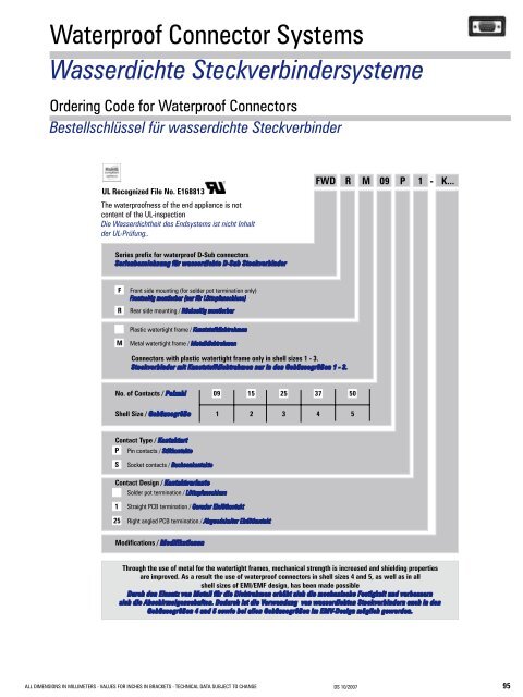
Ordering Code for <strong>Waterproof</strong> <strong>Connector</strong>s<br />
Bestellschlüssel für wasserdichte Steckverbinder<br />
UL Recognized File No. E168813<br />
The waterproofness of the end appliance is not<br />
content of the UL-inspection<br />
Die Wasserdichtheit des Endsystems ist nicht Inhalt<br />
der UL-Prüfung..<br />
ALL DIMENSIONS IN MILLIMETERS - VALUES FOR INCHES IN BRACKETS - TECHNICAL DATA SUBJECT TO CHANGE DS 10/2007<br />
95
Technical Data<br />
Technische Daten<br />
Mechanical Data<br />
Mechanische Daten<br />
Mechanical Data<br />
Mechanische Daten<br />
Protection standard / Schutzart DIN EN 60529 - IP 67<br />
Mating force per signal contact / Steckkraft pro Signalkontakt<br />
3,4 N<br />
Unmating force per signal contact / Ziehkraft pro Signalkontakt<br />
0,2 N<br />
Operating temperature range<br />
Betriebstemperaturbereich<br />
-25 °C bis +70 °C (-13 °F to +158 °F)<br />
Electrical Data<br />
Elektrische Daten<br />
Electrical Data<br />
Elektrische Daten<br />
Current rating<br />
Maximale Stromstärke<br />
5 A<br />
Test voltage between 2 contacts / shell and contact<br />
Prüfspannung zwischen 2 Kontakten bzw. Kontakt und Gehäuse<br />
1200 V / 1 min.<br />
Meets transitional resistance requirements per contact pair, in accordance<br />
with DIN 41652<br />
Erfüllt Übergangswiderstand pro Kontaktpaar nach DIN 41652 für<br />
- Straight contacts / gerade Kontakte ≤ 10 mΩ<br />
- Right angled contacts / abgewinkelte Kontakte ≤ 25 mΩ<br />
- Right angled contacts - 50 way / abgewinkelte Kontakte bei 50 Polen ≤ 35 mΩ<br />
Insulation resistance between contacts<br />
Isolationswiderstand Kontakt / Kontakt<br />
≥ 5000 MΩ<br />
Volume resistivity<br />
Spezifischer Durchgangswiderstand<br />
10 16 Ω cm<br />
Dielectric strength<br />
Spezifische Durchschlagsfestigkeit<br />
50 kV / mm<br />
Materials and Platings<br />
Materialien und Oberflächen<br />
Shell<br />
Gehäuse<br />
Insulator and plastic watertight frame<br />
Isolierkörper und Kunststoffdichtrahmen<br />
Metal watertight frame<br />
Metalldichtrahmen<br />
Contact material<br />
Kontaktmaterial<br />
Contacts<br />
Kontakte<br />
<strong>Waterproof</strong>ing elements<br />
Dichtelement<br />
Materials and Platings<br />
Materialien und Oberflächen<br />
Brass, tin plated over nickel<br />
Messing, verzinnt über Nickel<br />
Thermoplastic, glass filled (UL94V-0)<br />
Thermoplast, glasfaserverstärkt (UL94V-0)<br />
nickel plated zinc die-cast<br />
Zinkdruckguss, vernickelt<br />
Copper alloy<br />
Kupfer-Legierung<br />
Machined, copper alloy, 0.8 m (31 microinches) Au over Ni,<br />
termination area tin plated<br />
gedreht, Kupferlegierung, 0,8 m Au über Nickel,<br />
Anschlussbereich verzinnt<br />
Silicone<br />
Silikon<br />
96 DS 10/2007<br />
TECHNISCHE ÄNDERUNGEN VORBEHALTEN – MAßE IN MILLIMETER (INCHES IN KLAMMERN)
<strong>Waterproof</strong> <strong>Connector</strong>s with Plastic Watertight Frames<br />
<strong>Wasserdichte</strong> Steckverbinder mit Kunststoffdichtrahmen<br />
<strong>Connector</strong>s with Solder Pot Termination, Front Mounting<br />
Steckverbinder mit Löttopfanschluss, frontseitige Montage<br />
<strong>Connector</strong>s with Solder Pot Termination, max. AWG 20<br />
Steckverbinder mit Löttopfanschluss, max. AWG 20<br />
Number of Contacts A B Order Number Pin Order Number Socket Inner Thread<br />
Polzahl ±0,2 ±0,1 Bestellnummer Stift Bestellnummer Buchse Innengewinde<br />
(±0.008) (±0.004) 4-40 UNC M3<br />
9<br />
40,0 25,0<br />
Standard<br />
FWDF09P<br />
FWDF09S<br />
(1.575) (0.984) Standard<br />
-K413<br />
15<br />
48,3 33,3<br />
Standard<br />
FWDF15P<br />
FWDF15S<br />
(1.902) (1.311) Standard<br />
-K413<br />
25<br />
62,0 47,04<br />
Standard<br />
FWDF25P<br />
FWDF25S<br />
(2.441) (1.852) Standard<br />
-K413<br />
<strong>Connector</strong>s with Solder Pot Termination, Rear Mounting<br />
Steckverbinder mit Löttopfanschluss, rückseitige Montage<br />
<strong>Connector</strong>s with Solder Pot Termination, max. AWG 20<br />
Steckverbinder mit Löttopfanschluss, max. AWG 20<br />
Number of Contacts A B Order Number Pin Order Number Socket Inner Thread<br />
Polzahl ±0,2 ±0,1 Bestellnummer Stift Bestellnummer Buchse Innengewinde<br />
(±0.008) (±0.004) 4-40 UNC M3<br />
9<br />
40,0 25,0<br />
Standard<br />
FWDR09P<br />
FWDR09S<br />
(1.575) (0.984) Standard<br />
-K414<br />
15<br />
48,3 33,3<br />
Standard<br />
FWDR15P<br />
FWDR15S<br />
(1.902) (1.311) Standard<br />
-K414<br />
25<br />
62,0 47,04<br />
Standard<br />
FWDR25P<br />
FWDR25S<br />
(2.441) (1.852) Standard<br />
-K414<br />
ALL DIMENSIONS IN MILLIMETERS - VALUES FOR INCHES IN BRACKETS - TECHNICAL DATA SUBJECT TO CHANGE DS 10/2007<br />
97
<strong>Waterproof</strong> <strong>Connector</strong>s with Plastic Watertight Frame<br />
<strong>Wasserdichte</strong> Steckverbinder mit Kunststoffdichtrahmen<br />
<strong>Connector</strong>s with Straight PCB Termination<br />
Steckverbinder mit geradem Leiterplattenanschluss<br />
<strong>Connector</strong>s with Straight PCB Termination, Ø 0.6 mm (Ø 0.024"), Pre-tinned<br />
Steckverbinder mit geradem Einlötanschluss, Ø 0,6 mm, vorverzinnt<br />
Number of Contacts A B Order Number Pin Order Number Socket Inner Thread<br />
Polzahl ±0,2 ±0,1 Bestellnummer Stift Bestellnummer Buchse Innengewinde<br />
(±0.008) (±0.004) 4-40 UNC M3<br />
9<br />
40,0 25,0<br />
Standard<br />
FWDR09P1<br />
FWDR09S1<br />
(1.575) (0.984) Standard<br />
-K415<br />
15<br />
48,3 33,3<br />
Standard<br />
FWDR15P1<br />
FWDR15S1<br />
(1.902) (1.311) Standard<br />
-K415<br />
25<br />
62,0 47,04<br />
Standard<br />
FWDR25P1<br />
FWDR25S1<br />
(2.441) (1.852) Standard<br />
-K415<br />
PCB hole pattern: see page 20 Leiterplattenlochbilder: siehe Seite 20<br />
<strong>Connector</strong>s with Right Angled PCB Terminations<br />
Steckverbinder mit abgewinkeltem Leiterplattenanschluss<br />
<strong>Connector</strong>s with Right Angled PCB Termination, Ø 0.6 mm (Ø 0.024"), Pre-tinned<br />
Steckverbinder mit abgewinkeltem Einlötanschluss, Ø 0,6 mm, vorverzinnt<br />
Number of Contacts A B Order Number Pin Order Number Socket Inner Thread<br />
Polzahl ±0,2 ±0,1 Bestellnummer Stift Bestellnummer Buchse Innengewinde<br />
(±0.008) (±0.004) 4-40 UNC M3<br />
9<br />
40,0 25,0<br />
Standard<br />
FWDR09P25<br />
FWDR09S25<br />
(1.575) (0.984) Standard<br />
-K416<br />
15<br />
48,3 33,3<br />
Standard<br />
FWDR15P25<br />
FWDR15S25<br />
(1.902) (1.311) Standard<br />
-K416<br />
25<br />
62,0 47,04<br />
Standard<br />
FWDR25P25<br />
FWDR25S25<br />
(2.441) (1.852) Standard<br />
-K416<br />
PCB hole pattern: see page 20 Leiterplattenlochbilder: siehe Seite 20<br />
98 DS 10/2007<br />
TECHNISCHE ÄNDERUNGEN VORBEHALTEN – MAßE IN MILLIMETER (INCHES IN KLAMMERN)
<strong>Waterproof</strong> <strong>Connector</strong>s with Metal Watertight Frame<br />
<strong>Wasserdichte</strong> Steckverbinder mit Metalldichtrahmen<br />
<strong>Connector</strong>s with Solder Pot Termination, Front Mounting<br />
Steckverbinder mit Löttopfanschluss, frontseitige Montage<br />
<strong>Connector</strong>s with Solder Pot Termination, max. AWG 20<br />
Steckverbinder mit Löttopfanschluss, max. AWG 20<br />
Number of Contacts A B C Order number pin Order Number Socket Inner Thread On Request<br />
Polzahl ±0,2 ±0,1 ±0,2 Bestellnummer Stift Bestellnummer Buchse Innengewinde Auf Anfrage<br />
(±0.008) (±0.004) (±0.008) 4-40 UNC M3<br />
9<br />
40,0 25,0 21,0<br />
Standard<br />
FWDFM09P<br />
FWDFM09S<br />
(1.575) (0.984) (0.827) Standard<br />
-K413 •<br />
15<br />
48,3 33,3 21,0<br />
Standard<br />
FWDFM15P<br />
FWDFM15S<br />
(1.902) (1.311) (0.827) Standard<br />
-K413 •<br />
25<br />
62,0 47,04 21,00<br />
Standard<br />
FWDFM25P<br />
FWDFM25S<br />
(2.441) (1.852) (0.827) Standard<br />
-K413 •<br />
37<br />
78,5 63,5 21,0<br />
Standard<br />
FWDFM37P<br />
FWDFM37S<br />
(3.091) (2.500) (0.827) Standard<br />
-K413<br />
50<br />
76,1 61,1 23,2<br />
Standard<br />
FWDFM50P<br />
FWDFM50S<br />
(2.996) (2.406) (0.913) Standard<br />
-K413 •<br />
<strong>Connector</strong>s with Solder Pot Termination, Rear Mounting<br />
Steckverbinder mit Löttopfanschluss, rückseitige Montage<br />
<strong>Connector</strong>s with Solder Pot Termination, max. AWG 20<br />
Steckverbinder mit Löttopfanschluss, max. AWG 20<br />
Number of Contacts A B C Order Number Pin Order Number Socket Inner Thread On Request<br />
Polzahl ±0,2 ±0,1 ±0,2 Bestellnummer Stift Bestellnummer Buchse Innengewinde Auf Anfrage<br />
(±0.008) (±0.004) (±0.008) 4-40 UNC M3<br />
9<br />
40,0 25,0 21,0<br />
Standard<br />
FWDRM09P<br />
FWDRM09S<br />
(1.575) (0.984) (0.827) Standard<br />
-K414 •<br />
15<br />
48,3 33,3 21,0<br />
Standard<br />
FWDRM15P<br />
FWDRM15S<br />
(1.902) (1.311) (0.827) Standard<br />
-K414<br />
25<br />
62,0 47,04 21,00<br />
Standard<br />
FWDRM25P<br />
FWDRM25S<br />
(2.441) (1.852) (0.827) Standard<br />
-K414<br />
37<br />
78,5 63,5 21,0<br />
Standard<br />
FWDRM37P<br />
FWDRM37S<br />
(3.091) (2.500) (0.827) Standard<br />
-K414<br />
50<br />
76,1 61,1 23,2<br />
Standard<br />
FWDRM50P<br />
FWDRM50S<br />
(2.996) (2.406) (0.913) Standard<br />
-K414<br />
ALL DIMENSIONS IN MILLIMETERS - VALUES FOR INCHES IN BRACKETS - TECHNICAL DATA SUBJECT TO CHANGE DS 10/2007<br />
99
<strong>Waterproof</strong> <strong>Connector</strong>s with Metal Watertight Frame<br />
<strong>Wasserdichte</strong> Steckverbinder mit Metalldichtrahmen<br />
<strong>Connector</strong>s with Straight PCB Termination<br />
Steckverbinder mit geradem Leiterplattenanschluss<br />
<strong>Connector</strong>s with Straight PCB Termination, Ø 0.6 mm (Ø 0.024"), Pre-tinned<br />
Steckverbinder mit geradem Einlötanschluss, Ø 0,6 mm, vorverzinnt<br />
Number of Contacts A B C Order Number Pin Order Number Socket Inner Thread On Request<br />
Polzahl ±0,2 ±0,1 ±0,2 Bestellnummer Stift Bestellnummer Buchse Innengewinde Auf Anfrage<br />
(±0.008) (±0.004) (±0.008) 4-40 UNC M3<br />
9<br />
40,0 25,0 21,0<br />
Standard<br />
FWDRM09P1<br />
FWDRM09S1<br />
(1.575) (0.984) (0.827) Standard<br />
-K415 •<br />
15<br />
48,3 33,3 21,0<br />
Standard<br />
FWDRM15P1<br />
FWDRM15S1<br />
(1.902) (1.311) (0.827) Standard<br />
-K415<br />
25<br />
62,0 47,04 21,00<br />
Standard<br />
FWDRM25P1<br />
FWDRM25S1<br />
(2.441) (1.852) (0.827) Standard<br />
-K415<br />
37<br />
78,5 63,5 21,0<br />
Standard<br />
FWDRM37P1<br />
FWDRM37S1<br />
(3.091) (2.500) (0.827) Standard<br />
-K415<br />
50<br />
76,1 61,1 23,2<br />
Standard<br />
FWDRM50P1<br />
FWDRM50S1<br />
(2.996) (2.406) (0.913) Standard<br />
-K415<br />
PCB hole pattern: see page 20 Leiterplattenlochbilder: siehe Seite 20<br />
<strong>Connector</strong>s with Right Angled PCB Terminations<br />
Steckverbinder mit abgewinkeltem Leiterplattenanschluss<br />
<strong>Connector</strong>s with Right Angled PCB Termination, Ø 0.6 mm (Ø 0.024"), Pre-tinned<br />
Steckverbinder mit abgewinkeltem Einlötanschluss, Ø 0,6 mm, vorverzinnt<br />
Number of Contacts A B C D E Order Number Pin Order Number Socket Inner Thread On Request<br />
Polzahl ±0,2 ±0,1 ±0,2 ±0,1 ±0,2 Bestellnummer Stift Bestellnummer Buchse Innengewinde Auf Anfrage<br />
(±0.008) (±0.004) (±0.008) (±0.004) (±0.008) 4-40 UNC M3<br />
9<br />
40,0 25,0 21,0 7,3 11,6<br />
Standard<br />
FWDRM09P25<br />
FWDRM09S25<br />
(1.575) (0.984) (0.827) (0.287) (0.457) Standard<br />
-K416 •<br />
15<br />
48,3 33,3 21,0 7,3 11,6<br />
Standard<br />
FWDRM15P25<br />
FWDRM15S25<br />
(1.902) (1.311) (0.827) (0.287) (0.457) Standard<br />
-K416 •<br />
25<br />
62,0 47,04 21,0 7,3 11,6<br />
Standard<br />
FWDRM25P25<br />
FWDRM25S25<br />
(2.441) (1.852) (0.827) (0.287) (0.457) Standard<br />
-K416<br />
37<br />
78,5 63,5 21,0 7,3 11,6<br />
Standard<br />
FWDRM37P25<br />
FWDRM37S25<br />
(3.091) (2.500) (0.827) (0.287) (0.457) Standard<br />
-K416 •<br />
50<br />
76,1 61,1 23,2 8,8 12,84<br />
Standard<br />
FWDRM50P5<br />
FWDRM50S5<br />
(2.996) (2.406) (0.913) (0.346) (0.506) Standard<br />
-K416 •<br />
PCB hole pattern: see page 20 Leiterplattenlochbilder: siehe Seite 20<br />
100 DS 10/2007<br />
TECHNISCHE ÄNDERUNGEN VORBEHALTEN – MAßE IN MILLIMETER (INCHES IN KLAMMERN)
Front Mounting<br />
Frontseitige Montage<br />
Illustration:<br />
Mounting on the outer side of a machine with<br />
type FWDF09S (Please also see page 13).<br />
Abbildung:<br />
Montage auf der Geräteaußenseite bei Typ<br />
FWDF09S (siehe auch Seite 13).<br />
O-ring glued to frame<br />
O-Ring mit Dichtrahmen verklebt<br />
Metal watertight frame FWDFM<br />
Metalldichtrahmen FWDFM<br />
Rear Mounting<br />
Rückseitige Montage<br />
Illustration and drawing:<br />
Mounting on the inside of a machine with type<br />
FWDR09S (Please also see page 13).<br />
Abbildung und Zeichnung:<br />
Montage auf der Geräteinnenseite bei Typ<br />
FWDR09S (siehe auch Seite 13).<br />
O-ring glued onto frame<br />
O-Ring am Dichtrahmen verklebt<br />
Metal watertight frame FWDRM<br />
Metalldichtrahmen FWDRM<br />
Front panel<br />
Frontplatte<br />
Distance Bolts Available<br />
Lieferbare Abstandsbolzen<br />
Inner and Outer Thread Order Number<br />
Innen- und Außengewinde Bestellnummer<br />
M3<br />
F-GSCH1/5-K834<br />
4-40 UNC F-GSCH1/5-K835<br />
Spacer (for shell thickness 1.5 mm (0.059“) with thinner front panel,<br />
washers are required, which are included in the delivery.)<br />
Abstandsbolzen (für Gehäusewandstärke 1,5 mm, bei geringerer Stärke sind Unterlegscheiben<br />
notwendig, die im Lieferumfang enthalten sind.)<br />
Modifications of <strong>Waterproof</strong> <strong>Connector</strong>s<br />
Modifikationen wasserdichte Steckverbinder<br />
Modifications Additon to Order No. Order Example<br />
Modifikationen Bestellnummernergänzung Bestellbeispiel<br />
Mating Side<br />
Solder Side<br />
steckseitig<br />
lötseitig<br />
4-40 M3<br />
4-40 M3<br />
K577<br />
FWDF09S-K577<br />
4-40 4-40<br />
4-40 4-40<br />
—— FWDF09S1<br />
4-40 Solder eyelet<br />
4-40 Lötöse<br />
K708<br />
FWDR09P-K708<br />
M3<br />
Solder eyelet<br />
M3<br />
Lötöse<br />
K709<br />
FWDR09P-K709<br />
All connectors in the FWD series are assembled with front gaskets F1043<br />
Alle Steckverbinder der Baureihe FWD mit montierten Frontdichtungen F1043<br />
K1063<br />
FWDR09S-K1063<br />
ALL DIMENSIONS IN MILLIMETERS - VALUES FOR INCHES IN BRACKETS - TECHNICAL DATA SUBJECT TO CHANGE DS 10/2007<br />
101
Ordering Data (<strong>Waterproof</strong> D-Sub <strong>Connector</strong>s for FWH Hoods)<br />
Bestelldaten (wasserdichte D-Sub Steckverbinder für Hauben FWH)<br />
Pin <strong>Connector</strong><br />
Stiftsteckverbinder<br />
Socket <strong>Connector</strong><br />
Buchsensteckverbinder<br />
Order Number Shell Size Number of Contacts<br />
Bestellnummer Gehäusegröße Polzahl<br />
F09P-K700 1 9<br />
F15P-K700 2 15<br />
F25P-K700 3 25<br />
F37P-K700 4 37<br />
F50P-K700 5 50<br />
Order Number Shell Size Number of Contacts<br />
Bestellnummer Gehäusegröße Polzahl<br />
F09S-K700 1 9<br />
F15S-K700 2 15<br />
F25S-K700 3 25<br />
F37S-K700 4 37<br />
F50S-K700 5 50<br />
Packing Unit<br />
Verpackungseinheit<br />
Modification ...K701 Modifikation ...K701<br />
2 locking screws 2 St. Verriegelungsschrauben<br />
2 washers 2 St. Unterlegscheiben<br />
1 front seal 1 St. Frontdichtung<br />
2 distance bolts 2 St. Abstandsbolzen<br />
Information / Information:<br />
D-Sub pin and socket connectors for waterproof hoods are<br />
only available for solder pot terminations.<br />
Die D-Sub Stift- und Buchsensteckverbinder für wasserdichte<br />
Hauben sind nur mit Löttopfanschluss verfügbar.<br />
For information on FWH hoods, please refer to our hoods catalogue.<br />
Informationen zur Haube FWH entnehmen Sie bitte unserem Haubenkatalog.<br />
Accessories for Pin <strong>Connector</strong>s<br />
Zubehör für Stiftsteckverbinder<br />
Front Seal<br />
Frontdichtung<br />
Order Number Shell Size Number of Contacts<br />
Bestellnummer Gehäusegröße Polzahl<br />
F1043-1 1 9<br />
F1043-2 2 15<br />
F1043-3 3 25<br />
F1043-4 4 37<br />
F1043-5 5 50<br />
Material Specification<br />
Materialbeschreibung<br />
Material Silicone<br />
Material Silikon<br />
Thickness 0,8<br />
Dicke (0.031)<br />
Front seals are used to seal off the connection area of the signal contacts (combination FWD... with D-Sub connectors ...-K700) and are mounted in male<br />
connectors (see drawing). They can also be used with standard D-Sub connectors.<br />
Frontdichtungen dienen zur Abdichtung des Steckbereiches der Signalkontakte (Kombination FWD... mit D-Sub Steckverbindern ...-K700) und werden im<br />
Stiftstecker montiert (siehe Zeichnung). Sie sind auch mit Standard D-Sub Steckverbindern verwendbar.<br />
102 DS 10/2007<br />
TECHNISCHE ÄNDERUNGEN VORBEHALTEN – MAßE IN MILLIMETER (INCHES IN KLAMMERN)