Montageanleitung/Instructions HALFEN HUC Universal connection
Montageanleitung/Instructions HALFEN HUC Universal connection
Montageanleitung/Instructions HALFEN HUC Universal connection

Sie wollen auch ein ePaper? Erhöhen Sie die Reichweite Ihrer Titel.
YUMPU macht aus Druck-PDFs automatisch weboptimierte ePaper, die Google liebt.
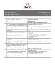
<strong>HALFEN</strong> <strong>HUC</strong> INST_<strong>HUC</strong> 09/13<br />
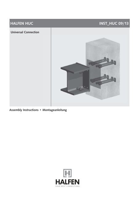
<strong>Universal</strong> Connection<br />
Assembly <strong>Instructions</strong> • <strong>Montageanleitung</strong>
<strong>HALFEN</strong> <strong>HUC</strong><br />
Assembly <strong>Instructions</strong><br />
Application examples<br />
Deutsch English<br />
<strong>HALFEN</strong> <strong>HUC</strong> <strong>Universal</strong> Connection<br />
has a wide range of application possibilities.<br />
This assembly instruction<br />
describes the <strong>connection</strong> of a steel<br />
beam/steel corbel to a concrete<br />
column.<br />
Number, shape and layout of the<br />
anchor bars, as well as the attached<br />
construction elements may vary in<br />
each individual case.<br />
!<br />
The engineer’s specifications<br />
(for installation, position, additional<br />
reinforcement, etc.) have<br />
to be observed.<br />
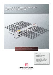
Steel beam <strong>connection</strong> <strong>HALFEN</strong> HSCC Steel corbel <strong>connection</strong> Customized steel constructions<br />
Product overview<br />
Cast-in concrete<br />
Steel construction<br />
HSC-B FP Face plate<br />
HSC-B SH<br />
Single headed,<br />
female bar<br />
HSC-B S<br />
Female bar<br />
HSC-B SD<br />
Double headed,<br />
female bar<br />
HSC-B SB<br />
Bent female bar<br />
or HSCC Steel corbel<br />
Identification<br />
HSC-B P<br />
Positioning plate<br />
(example)<br />
Identification<br />
Accessories<br />
HSC-B FI<br />
Flat-headed screw;<br />
head 3 mm<br />
HSC-B FI<br />
adhesive<br />
sealing tape<br />
Identification<br />
2 © 2013 <strong>HALFEN</strong> · INST_<strong>HUC</strong> 09/13 · www.halfen.com
<strong>HALFEN</strong> <strong>HUC</strong><br />
Assembly <strong>Instructions</strong><br />
Identification<br />
Assembling example<br />
Stud heads<br />
HSC<br />
20<br />
Factory mark<br />
Product name<br />
bar diameter<br />
d S = 12 - 16 - 20 - 25 mm<br />
<strong>HALFEN</strong> HSC-B Concrete steel <strong>connection</strong><br />
with 2x4 female bars fitted<br />
to a steel beam or a steel corbel to<br />
a reinforced concrete column<br />
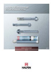
1. Check the hole layout of the positioning<br />
and front plate before installing.<br />
Horizontal anchor-head placement<br />
Deutsch English<br />
Sleeves<br />
HSC-B<br />
20/M20<br />
xyy-z<br />
Standard design<br />
Product name<br />
Bar diam./ Thread<br />
Factory mark<br />
2. Replace the thread<br />
protection cap.<br />
3. Assembly of the HSC-B Concrete<br />
steel connector – female bars are<br />
fixed with flat headed screws<br />
to the positioning plate. Bar type<br />
and position are according to the<br />
engineer’s specification.<br />
5. Cut and fit self adhesive foam-tape<br />
to form a recess in the concrete at<br />
the <strong>connection</strong> location.<br />
When used with steel formwork a<br />
magnet is placed in the middle of<br />
the positioning plate.<br />
HSC-B<br />
20/M20<br />
A 4<br />
xyy-z<br />
Product name<br />
Bar diam./ Thread<br />
Material design<br />
Factory mark<br />
Design with A4 stainless steel<br />
This type of assembly requires no<br />
formwork penetration. The positioning<br />
plate is not flush with the formwork.<br />
Female bars<br />
Bar diam.<br />
d s<br />
Thread<br />
Colour of<br />
protection<br />
plug<br />
12 M 12 x 1.75* green<br />
16 M 16 x 2.0* orange<br />
20 M 20 x 2.5* bright blue<br />
25 M 27 x 3.0* yellow<br />
* Metric ISO standard thread<br />
(DIN 13-1)<br />
4. Stud heads can be aligned horizontally<br />
or vertically. The engineer’s<br />
specifications have to be observed.<br />
Vertical anchor-head placement<br />
© 2013 <strong>HALFEN</strong> · INST_<strong>HUC</strong> 09/13 · www.halfen.com<br />
3
<strong>HALFEN</strong> <strong>HUC</strong><br />
Assembly <strong>Instructions</strong><br />
Assembling example<br />
Deutsch English<br />
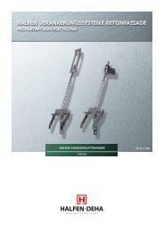
6. <strong>HALFEN</strong> HSC-B Concrete steel connector<br />
is attached with magnets<br />
to steel formwork or by nailing<br />
to wooden formwork.<br />
Alternative:<br />
Formwork penetration type;<br />
the positioning plate is flush with<br />
the formwork<br />
7. The column and additional reinforcement<br />
are installed according<br />
to the design drawings provided<br />
by the structural engineer.<br />
!<br />
Positioning plate<br />
Observe the different<br />
edge distances of the<br />
bolt holes in the<br />
positioning plate and<br />
the face plate<br />
8. To secure the position of the<br />
bars they are wire-tied to the<br />
longitudinal column reinforcement.<br />
Face plate<br />
d 1<br />
d 2<br />
4 © 2013 <strong>HALFEN</strong> · INST_<strong>HUC</strong> 09/13 · www.halfen.com
<strong>HALFEN</strong> <strong>HUC</strong><br />
Assembly <strong>Instructions</strong><br />
Assembling example<br />
Welding, even spot welding, can<br />
seriously impair material properties.<br />
For this reason welding and heat input<br />
in the thread area, in the stud<br />
head area and near the sleeves is forbidden.<br />
Other welding not in the<br />
mentioned areas must be carried out<br />
according to recognized welding regulations<br />
and guidelines; these welds<br />
are the sole responsibility of the contractor<br />
or welder.<br />
The positioning plate needs to be<br />
secured in place by reinserting the<br />
thread protection caps for the whole<br />
installation process; especially when<br />
transporting prefabricated elements.<br />
This also protects the threads from<br />
corrosion.<br />
Installation of <strong>HALFEN</strong> HSCC<br />
type tested steel corbel<br />
Deutsch English<br />
!<br />
10. Assembly of the structural steel<br />
element<br />
9. Pouring the concrete for the column<br />
The concrete cover specified in the<br />
design drawing also applies to the<br />
stud heads.<br />
Anchorage in columns: the stud heads<br />
must be positioned behind the rear<br />
longitudinal column reinforcement.<br />
min 1 d s<br />
Installation of a steel beam,<br />
prefabricated with<br />
<strong>HALFEN</strong> HSC-B FP Face plates<br />
c = Concrete cover<br />
c<br />
The minimum screw depth of 1 d s<br />
must be observed.<br />
The torques values for bolts are<br />
set according to the construction<br />
situation. The following maximum<br />
preload values must be observed<br />
when preloading bolts:<br />
The gap between the positioning<br />
plate and the formwork needs to be<br />
protected against concrete penetration.<br />
Redundant bolt holes etc. must be<br />
sealed; use silicone sealant if necessary.<br />
Maximum preload value [kN]<br />
M12 31,1<br />
M16 58,6<br />
M20 91,6<br />
M27 173,3<br />
© 2013 <strong>HALFEN</strong> · INST_<strong>HUC</strong> 09/13 · www.halfen.com<br />
5
<strong>HALFEN</strong> <strong>HUC</strong><br />
<strong>Montageanleitung</strong><br />
Anwendungsbeispiele<br />
Deutsch English<br />
Die <strong>HALFEN</strong> <strong>HUC</strong> <strong>Universal</strong> Connection<br />
bietet eine Vielzahl von Variationsmöglichkeiten.<br />
Diese <strong>Montageanleitung</strong><br />
erläutert die Verbindung<br />
eines Stahlträgers/Stahlkonsole mit<br />
einer Stahlbetonstütze. Die Anzahl,<br />
Form und Anordnung der Ankerstäbe,<br />
sowie die Ausführung der Anschlussbauteile<br />
kann im Einzelfall hiervon abweichen.<br />
!<br />
Die Angaben des Planers (Einbaulage,<br />
Betondeckung, Zulagebewehrung<br />
etc.) sind zu beachten.<br />
Anschluss von Stahlträgern Anschluss: <strong>HALFEN</strong> HSCC Stahlkonsolen Individueller Stahlbauanschluss<br />
Produktübersicht<br />
Betonseitig<br />
Stahlbauteil<br />
HSC-B FP Stirnplatte<br />
HSC-B SH<br />
Muffenstab<br />
HSC-B S<br />
Muffenstab<br />
einseitig<br />
HSC-B SD<br />
Doppelmuffenstab<br />
HSC-B SB<br />
Muffenstab, gebogen<br />
oder HSCC Stahlkonsole<br />
Kennzeichnung<br />
HSC-B P<br />
Positionsplatte<br />
(Beispiel)<br />
Kennzeichnung<br />
Zubehör<br />
HSC-B FI<br />
Flachkopfschraube;<br />
Kopf 3 mm<br />
HSC-B SE<br />
dauerelastisches<br />
Dichtungsband<br />
Kennzeichnung<br />
6 © 2013 <strong>HALFEN</strong> · INST_<strong>HUC</strong> 09/13 · www.halfen.com
<strong>HALFEN</strong> <strong>HUC</strong><br />
<strong>Montageanleitung</strong><br />
Kennzeichnung<br />
Montagebeispiel<br />
Ankerköpfe<br />
HSC<br />
20<br />
Werkskennzeichnung<br />
Produktbezeichnung<br />
Stabdurchmesser<br />
d S = 12 - 16 - 20 - 25 mm<br />
<strong>HALFEN</strong> HSC-B Stahlbauanschluss<br />
mit 2 x 4 Muffenstäben zur Befestigung<br />
eines Stahlträgers oder einer<br />
Stahlkonsole an eine Stahlbetonstütze<br />
1. Prüfen des Lochbildes in Positionsund<br />
Stirnplatte vor dem Einbau<br />
Horizontale Ankerkopfausrichtung<br />
Deutsch English<br />
Muffen<br />
HSC-B<br />
20/M20<br />
xyy-z<br />
Standardausführung<br />
HSC-B<br />
20/M20<br />
A 4<br />
xyy-z<br />
Ausführung A4 Edelstahl<br />
Produktbezeichnung<br />
Stabdurchmesser/<br />
Gewinde<br />
Werkskennzeichnung<br />
Produktbezeichnung<br />
Stabdurchmesser/<br />
Gewinde<br />
Materialausführung<br />
Werkskennzeichnung<br />
2. Entfernen der Gewindeverschlussschraube<br />
3. Zusammenbau des HSC-B Stahlbauanschlusses<br />
– Muffenstäbe<br />
werden mit flachen Schrauben an<br />
die Positionsplatte geschraubt.<br />
Ausführung und Position der Muffenstäbe<br />
entsprechend den Angaben<br />
des Planers<br />
5. Zuschnitt und Aufbringen der Abdichtung<br />
gegen Eindringen von<br />
Beton in die HSC-B Aussparung.<br />
Evtl. Magnete als Montagehilfe für<br />
den Einsatz von Stahlschalung<br />
anbringen.<br />
Diese Montagevariante benötigt keine<br />
Schalungsdurchdringungen. Die Positionsplatte<br />
liegt nicht schalungsbündig.<br />
Muffenstäbe<br />
Stabdurchmesser<br />
d s<br />
Gewinde<br />
12 M 12 x 1.75* grün<br />
Farbe der<br />
Gewindestopfen<br />
16 M 16 x 2,0* orange<br />
20 M 20 x 2,5* hellblau<br />
25 M 27 x 3,0* gelb<br />
* Metrisches ISO - Regelgewinde<br />
(DIN 13-1)<br />
4. Ankerköpfe können horizontal<br />
oder vertikal ausgerichtet sein.<br />
Es gelten die Festlegungen des<br />
Planers.<br />
Vertikale Ankerkopfausrichtung<br />
© 2013 <strong>HALFEN</strong> · INST_<strong>HUC</strong> 09/13 · www.halfen.com<br />
7
<strong>HALFEN</strong> <strong>HUC</strong><br />
<strong>Montageanleitung</strong><br />
Montagebeispiel<br />
Deutsch English<br />
6. Der <strong>HALFEN</strong> HSC-B Anschluss wird<br />
mit den Magneten an einer Stahlschalung<br />
oder durch Nageln an einer<br />
Holzschalung befestigt<br />
Alternative:<br />
Montage mit<br />
Schalungsdurchdringung,<br />
Positionsplatte schalungsbündig<br />
7. Einlegen der Stützen- und Zulagebewehrung<br />
nach Angaben des<br />
Statikers.<br />
!<br />
Unterschiedliche Randabstände<br />
für Schraubenlöcher<br />
in Positions- und<br />
Stirnplatte beachten.<br />
Positionsplatte<br />
Stirnplatte<br />
8. Die Lagesicherung der Muffenstäbe<br />
erfolgt durch Feströdeln an<br />
der Stützenlängsbewehrung.<br />
d 1<br />
d 2<br />
8 © 2013 <strong>HALFEN</strong> · INST_<strong>HUC</strong> 09/13 · www.halfen.com
<strong>HALFEN</strong> <strong>HUC</strong><br />
<strong>Montageanleitung</strong><br />
Montagebeispiel<br />
Schweißen, auch Punktschweißen,<br />
kann die Materialeigenschaften negativ<br />
beeinflussen und ist im Bereich des<br />
Gewindes der Ankerköpfe und Muffen<br />
nicht zulässig.<br />
Schweißungen außerhalb dieser Bereiche<br />
sind nach gültigen Schweißvorschriften<br />
durchzuführen und liegen in<br />
der Verantwortung des Ausführenden.<br />
Die Positionsplatte muss während der<br />
gesamten Montage, insbesondere<br />
beim Transport von Fertigteilen, durch<br />
Eindrehen der Gewindeschutzschraube<br />
gegen Herausfallen gesichert werden.<br />
Die Gewinde werden hiermit<br />
auch vor Korrosion geschützt.<br />
Montage von <strong>HALFEN</strong> HSCC<br />
typengeprüften Stahlkonsolen<br />
Deutsch English<br />
!<br />
10. Montage des Stahlbauteils<br />
9. Betonieren der Stütze<br />
Die auf den Plänen angegebene Betondeckung<br />
muss auch für die Ankerköpfe<br />
eingehalten werden.<br />
Verankerung in der Stütze: Die Ankerköpfe<br />
müssen bis hinter die Stützenlängsbewehrung<br />
geführt werden.<br />
min 1 d s<br />
Montage individueller mit der<br />
<strong>HALFEN</strong> HSC-B Stirnplatte vorgfertigter<br />
Stahlträger<br />
c = Betondeckung<br />
c<br />
Die Mindesteinschraubtiefe für die<br />
Endmontage von 1 d s ist zu beachten.<br />
Die Anzugsmomente für die Schrauben<br />
sind entsprechend der baulichen<br />
Begebenheiten zu ermitteln.<br />
Beim Vorspannen der Schrauben<br />
sind die maximal zulässigen Vorspannkräfte<br />
zu beachten:<br />
Der Raum zwischen der Positionsplatte<br />
und der Schalung muss vor<br />
Betoneintritt geschützt werden. Nicht<br />
belegte Schraubenlöcher etc. sind zu<br />
verschließen und ggf. zusätzlich mit<br />
Silikon abzudichten.<br />
Maximale Vorspannkräfte [kN]<br />
M12 31,1<br />
M16 58,6<br />
M20 91,6<br />
M27 173,3<br />
© 2013 <strong>HALFEN</strong> · INST_<strong>HUC</strong> 09/13 · www.halfen.com<br />
9
CONTACT <strong>HALFEN</strong> WORLDWIDE<br />
<strong>HALFEN</strong> is represented by subsidiaries in the following 14 countries, please contact us:<br />
Austria<br />
Belgium /<br />
Luxembourg<br />
China<br />
Czech Republic<br />
France<br />
Germany<br />
Italy<br />
Netherlands<br />
Norway<br />
Poland<br />
Sweden<br />
Switzerland<br />
United Kingdom /<br />
Ireland<br />
United States of<br />
America<br />
<strong>HALFEN</strong> Gesellschaft m.b.H.<br />
Leonard-Bernstein-Str. 10<br />
1220 Wien<br />
<strong>HALFEN</strong> N.V.<br />
Borkelstraat 131<br />
2900 Schoten<br />
<strong>HALFEN</strong> Construction Accessories Distribution Co.Ltd.<br />
Room 601 Tower D, Vantone Centre<br />
No.A6 Chao Yang Men Wai Street<br />
Chaoyang District<br />
Beijing · P.R. China 100020<br />
<strong>HALFEN</strong>-DEHA s.r.o.<br />
Business Center Šafránkova<br />
Šafránkova 1238/1<br />
155 00 Praha 5<br />
<strong>HALFEN</strong> S.A.S.<br />
18, rue Goubet<br />
75019 Paris<br />
<strong>HALFEN</strong> Vertriebsgesellschaft mbH<br />
Katzbergstrasse 3<br />
40764 Langenfeld<br />
<strong>HALFEN</strong> S.r.l. Soc. Unipersonale<br />
Via F.lli Bronzetti N° 28<br />
24124 Bergamo<br />
<strong>HALFEN</strong> b.v.<br />
Oostermaat 3<br />
7623 CS Borne<br />
<strong>HALFEN</strong> AS<br />
Postboks 2080<br />
4095 Stavanger<br />
<strong>HALFEN</strong> Sp. z o.o.<br />
Ul. Obornicka 287<br />
60-691 Poznan<br />
Halfen AB<br />
Box 150<br />
435 23 Mölnlycke<br />
<strong>HALFEN</strong> Swiss AG<br />
Hertistrasse 25<br />
8304 Wallisellen<br />
<strong>HALFEN</strong> Ltd.<br />
Humphrys Road · Woodside Estate<br />
Dunstable LU5 4TP<br />
<strong>HALFEN</strong> USA Inc.<br />
8521 FM 1976<br />
P.O. Box 547<br />
Converse, TX 78109<br />
Phone: +43 - 1 - 2596770<br />
E-Mail: office@halfen.at<br />
Internet: www.halfen.at<br />
Phone: +32 - 3 - 6580720<br />
E-Mail: info@halfen.be<br />
Internet: www.halfen.be<br />
Phone: +86 - 10 5907 3200<br />
E-Mail: info@halfen.cn<br />
Internet: www.halfen.cn<br />
Phone: +420 - 311 - 690 060<br />
E-Mail: info@halfen-deha.cz<br />
Internet: www.halfen-deha.cz<br />
Phone: +33 - 1 - 44523100<br />
E-Mail: halfen@halfen.fr<br />
Internet: www.halfen.fr<br />
Phone: +49 - 2173 - 9700<br />
E-Mail: info@halfen.de<br />
Internet: www.halfen.de<br />
Phone: +39 - 035 - 0760711<br />
E-Mail: info@halfen.it<br />
Internet: www.halfen.it<br />
Phone: +31 - 74-267 1449<br />
E-Mail: info@halfen.nl<br />
Internet: www.halfen.nl<br />
Phone: +47 - 51823400<br />
E-Mail: post@halfen.no<br />
Internet: www.halfen.no<br />
Phone: +48 - 61 - 6221414<br />
E-Mail: info@halfen.pl<br />
Internet: www.halfen.pl<br />
Phone: +46 - 31 - 985800<br />
E-Mail: info@halfen.se<br />
Internet: www.halfen.se<br />
Phone: +41 - 44 - 8497878<br />
E-Mail: mail@halfen.ch<br />
Internet: www.halfen.ch<br />
Phone: +44 - 1582 - 470300<br />
E-Mail: info@halfen.co.uk<br />
Internet: www.halfen.co.uk<br />
Phone: +1 800.323.68 96<br />
E-Mail: info@halfenusa.com<br />
Internet: www.halfenusa.com<br />
Fax: +43 - 1 - 259 - 677099<br />
Fax: +32 - 3 - 6581533<br />
Fax: +86 - 1059073218<br />
Fax: +420 - 235 - 314308<br />
Fax: +33 - 1 - 44523152<br />
Fax: +49 - 2173 - 970225<br />
Fax: +39 - 035 - 0760799<br />
Fax: +31 - 74-267 2659<br />
Fax: +47 - 51823401<br />
Fax: +48 - 61 - 6221415<br />
Fax: +46 - 31 - 985801<br />
Fax: +41 - 44 - 8497879<br />
Fax: +44 - 1582 - 470304<br />
Fax: +1 877 . 683.4910<br />
For countries not <strong>HALFEN</strong> International GmbH<br />
listed<br />
Liebigstr. 14<br />
<strong>HALFEN</strong> International 40764 Langenfeld / Germany<br />
Phone: +49 - 2173 - 970 - 0<br />
E-Mail: info@halfen.com<br />
Internet: www.halfen.com<br />
Fax: +49 - 2173 - 970 - 849<br />
Furthermore <strong>HALFEN</strong> is represented with sales offices and distributors worldwide.<br />
Please contact us: www.halfen.com<br />
NOTES REGARDING THIS DOCUMENT<br />
Technical and design changes reserved. The information in this publication is based on state-of-the-art technology<br />
at the time of publication. We reserve the right to make technical and design changes at any time. Halfen GmbH<br />
shall not accept liability for the accuracy of the information in this publication or for any printing errors.<br />
The Quality Management System of Halfen GmbH is certified for the locations in Germany, France, the Netherlands,<br />
Austria, Poland, Switzerland and the Czech Republic acc. to DIN EN ISO 9001:2008, Certificate No. QS-281 HH.
230<br />
U - 107 - 10/13 2.000 10/13<br />
© 2013 <strong>HALFEN</strong> GmbH, Germany<br />
applies also to copying in extracts.