PDF öffnen
PDF öffnen
PDF öffnen

Sie wollen auch ein ePaper? Erhöhen Sie die Reichweite Ihrer Titel.
YUMPU macht aus Druck-PDFs automatisch weboptimierte ePaper, die Google liebt.
82 | Schüco<br />
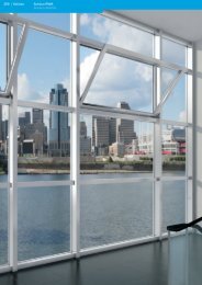
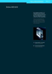
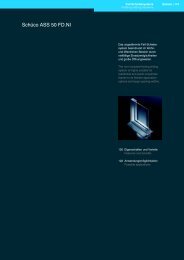
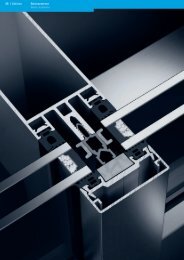
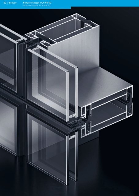
Schüco Fassade UCC 65 SG<br />
Schüco Façade UCC 65 SG
Schüco Fassade UCC 65 SG<br />
Schüco Façade UCC 65 SG<br />
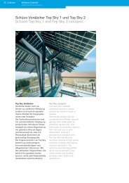
Schüco UCC 65 SG (Unitized<br />
Customised Construction)<br />
kombiniert die architektonisch<br />
hochwertige Optik einer<br />
Structural Glazing-Fassade mit<br />
der standardisierten Objektbearbeitung<br />
eines leistungsstarken<br />
und flexiblen Systembaukasten<br />
bei gleichzeitig individuellen<br />
Gestaltungsmöglichkeiten.<br />
Schüco UCC 65 SG (Unitised<br />
Customised Construction)<br />
combines the high-quality look of<br />
a structural glazing façade with<br />
the standardised project<br />
processing of a high-performance<br />
and flexible modular system,<br />
whilst at the same time providing<br />
individual design options.<br />
Schüco Fassade UCC 65 SG<br />
Schüco Façade UCC 65 SG<br />
82 Systemeigenschaften<br />
System properties<br />
86 Prüfzeugnisse<br />
Test certificates<br />
89 Konstruktionsprinzipien<br />
Construction principles<br />
99 Anwendungsbeispiele<br />
Examples<br />
120 Profilübersicht<br />
Overview of profiles<br />
Schüco | 83<br />
Schüco UCC 65 SG
84 | Schüco<br />
Maßstab 1:1<br />
Scale 1:1<br />
Systemeigenschaften<br />
System properties<br />
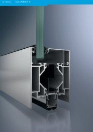
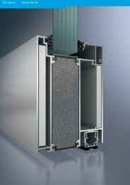
Systemeigenschaften Schüco Fassade UCC 65 SG<br />
System properties for Schüco Façade UCC 65 SG<br />
65<br />
12<br />
Eigenschaften und Vorteile<br />
• Elementbauweise zur besonders rationellen<br />
Fertigung und Montage<br />
• Attraktive Ganzglasoptik<br />
• Besonders schmale Ansichtsbreite bis 65 mm<br />
• Variables Dichtungsprogramm:<br />
• 10 mm horizontale Stoßfuge, Aufnahme von<br />
+/- 5 mm Dehnung<br />
• 20 mm horizontale Stoßfuge, Aufnahme von<br />
+/- 10 mm Dehnung<br />
• System Schüco e-connect<br />
• Tüllen zur Leitungsdurchführung<br />
• Keine Beschädigung der Leitungen beim<br />
Leitungsübergang<br />
• Reduzierte Gefahr fehlerhafter elektrischer<br />
Anschlüsse durch eindeutige Gewerkeschnittstellen<br />
mit der Schüco e-Box<br />
• Formteile zur Fixierung elektrischer Leitungen<br />
in den umlaufenden Rahmenprofilen der<br />
Elementfassade<br />
• Einsatzelemente<br />
• Schüco AWS 102 wahlweise als Senkklappoder<br />
Parallel-Ausstell-Fenster<br />
• Die Einsatzelemente können wahlweise<br />
hand- oder motorbetätigt werden<br />
• Umfangreiche Systemprüfungen nach<br />
europäischen und amerikanischen Prüfnormen<br />
Features and benefits<br />
• Unitised construction means particularly efficient<br />
fabrication and assembly<br />
• Attractive fully glazed look<br />
• Exceptionally narrow face widths (up to 65 mm)<br />
• Different gasket options:<br />
• 10 mm horizontal butt joint, to take up an<br />
expansion of +/- 5 mm<br />
• 20 mm horizontal butt joint, to take up an<br />
expansion of +/- 10 mm<br />
• Schüco e-connect system<br />
• Grommets to carry the wiring<br />
• No damage to the wiring where cable is<br />
connected<br />
• The Schüco e-box has a single connection<br />
interface to reduce danger of defective<br />
electrical connections<br />
• Shaped components for fixing electrical wiring<br />
in the continuous frame profiles of the unitised<br />
façade<br />
• Insert units<br />
• Schüco AWS 102 insert units either as<br />
projected top-hung or parallel-opening<br />
windows<br />
• The insert units can be operated manually or<br />
electrically<br />
• Extensive system tests in accordance with<br />
European and American test standards
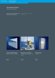
Übersicht der Systemvarianten<br />
Overview of system options<br />
Schüco Fassade UCC 65 SG<br />
Schüco Façade UCC 65 SG<br />
Maßstab 1:2<br />
Scale 1:2<br />
1-teiliges Rahmenprofil<br />
mit Kopplungsdichtung,<br />
Direktverklebung auf<br />
dem Elementrahmen<br />
1-part frame profile with<br />
coupling gasket,direct<br />
bonding to the unit<br />
frame<br />
2-teiliges Rahmenprofil<br />
mit Kopplungsdichtung,<br />
Verklebung auf dem<br />
Adapterprofil<br />
2-part frame profile with<br />
coupling gasket,bonding<br />
to the adapter profile<br />
Systemeigenschaften<br />
System properties<br />
1-teiliges Rahmenprofil<br />
mit Kopplungsprofil und<br />
Einzeldichtungen,<br />
Direktverklebung auf<br />
dem Elementrahmen<br />
1-part frame profile with<br />
coupling profile and<br />
individual gaskets,direct<br />
bonding to the unit<br />
frame<br />
2-teiliges Rahmenprofil<br />
mit Kopplungsprofil und<br />
Einzeldichtungen,<br />
Verklebung auf dem<br />
Adapterprofil<br />
2-part frame profile with<br />
coupling profile and<br />
individual<br />
gaskets,bonding to the<br />
adapter profile<br />
Schüco | 85<br />
Schüco UCC 65 SG
86 | Schüco<br />
Art der Prüfung<br />
Type of test<br />
Prüfzeugnisse<br />
Test certificates<br />
Prüfzeugnisse<br />
Test certificates<br />
Luftdurchlässigkeit<br />
Air permeability<br />
Schlagregendichtigkeit<br />
Watertightness<br />
Absturzsicherheit (Pendelschlagversuch)<br />
Safety (pendulum impact test)<br />
Luftschalldämmung<br />
Airborne sound reduction<br />
Längsschalldämmung horizontal<br />
Horizontal noise transmission insulation<br />
Längsschalldämmung vertikal<br />
Vertical noise transmission insulation<br />
Wärmedämmung<br />
Thermal insulation<br />
Zulassung<br />
Approval<br />
Norm<br />
Standard<br />
EN 12152<br />
AAMA 501-5<br />
EN 12154<br />
AAMA 501-5<br />
Prüfinstitut<br />
Test institute<br />
ift - Rosenheim<br />
ATI<br />
ift - Rosenheim<br />
ATI<br />
Prüfzeugnis<br />
Test certificate<br />
108 28296/1<br />
54028.03-120-47<br />
108 28296/2<br />
54028.03-120-47<br />
DIN EN 12600 PSP Technologie im Bauwesen S-113-01-1<br />
EN ISO 717-1<br />
ASTM E 413<br />
EN ISO 717-1<br />
ASTM E 413<br />
EN ISO 717-1<br />
ASTM E 413<br />
DIN EN ISO 10077, T2<br />
ETAG 002<br />
ift - Rosenheim 16928386/2<br />
ift - Rosenheim 16928386/2<br />
ift - Rosenheim 16928386/2<br />
eigene Berechnung<br />
Own calculation<br />
OIB (Österreichisches Institut<br />
für Bautechnik<br />
ETA beantragt<br />
ETA pending<br />
Prüfergebnis<br />
Test result<br />
AE<br />
12,5 psf<br />
RE 1200<br />
30 psf<br />
voll absturzsichernd<br />
Full safety barrier<br />
R‘ 45°,w = 40 dB<br />
[6-(12)-9 VSG SF]<br />
R‘ 45°,w = 36 dB<br />
[6-(16)-6 VSG SF]<br />
D n, f, w 48 - 50 dB<br />
STC 44 - 48 dB<br />
D n, f, w 57 - 59 dB<br />
STC 57 - 60 dB<br />
siehe nachfolgende Seite<br />
See following page<br />
auf Anfrage<br />
On request
Schallschutz<br />
Sound reduction<br />
Bewertetes Schalldämm-Maß<br />
Airborne sound reduction index<br />
Schüco-System<br />
Schüco system<br />
Luftschalldämmung / Airborne sound reduction<br />
R‘ 45°,w = 40 dB<br />
R‘ 45°,w = 36 dB<br />
R‘ 45°,w = 40 dB<br />
R‘ 45°,w = 36 dB<br />
12<br />
12<br />
127<br />
X<br />
130<br />
X<br />
1 - teilig<br />
1-part<br />
2 - teilig<br />
2-part<br />
Empfohlene Verglasung<br />
Recommended glazing<br />
[6-(12)-9 VSG SF]<br />
[6-(16)-6]<br />
[6-(12)-9 VSG SF]<br />
[6-(16)-6]<br />
Prüfzeugnisse<br />
Test certificates<br />
Schüco | 87<br />
Schüco UCC 65 SG
88 | Schüco<br />
Prüfzeugnisse<br />
Test certificates<br />
Wärmedämmung<br />
Thermal insulation<br />
Rahmenprofil, 1- und 2-teilig<br />
Frame profile, 1 and 2-part<br />
Maßstab 1:2<br />
Scale 1:2<br />
12<br />
12<br />
127<br />
X<br />
130<br />
X<br />
U f -Wert in W/m²K nach DIN EN ISO 10077, T2<br />
U f value in W/m²K in accordance with DIN EN ISO 10077, part 2<br />
x<br />
mm [W/(m²∙K)]<br />
x = 28 2,16<br />
x = 34 2,15<br />
U f -Wert in W/m²K nach DIN EN ISO 10077, T2<br />
U f value in W/m²K in accordance with DIN EN ISO 10077, part 2<br />
x<br />
mm [W/(m²∙K)]<br />
x = 28 2,16<br />
x = 34 2,15
Sprossenprofil, 1- und 2-teilig<br />
Glazing bar, 1 and 2-part<br />
Maßstab 1:2<br />
Scale 1:2<br />
12<br />
12<br />
126<br />
X<br />
X 129<br />
x<br />
Prüfzeugnisse<br />
Test certificates<br />
U f -Wert in W/m²K nach DIN EN ISO 10077, T2<br />
U f value in W/m²K in accordance with DIN EN ISO 10077, part 2<br />
mm [W/(m²∙K)]<br />
x = 28 2,41<br />
x = 34 2,42<br />
U f -Wert in W/m²K nach DIN EN ISO 10077, T2<br />
U f value in W/m²K in accordance with DIN EN ISO 10077, part 2<br />
x<br />
mm [W/(m²∙K)]<br />
x = 28 2,41<br />
x = 34 2,42<br />
Schüco | 89<br />
Schüco UCC 65 SG
90 | Schüco<br />
Konstruktionsprinzipien<br />
Construction principles<br />
Konstruktionsprinzipien<br />
Construction principles<br />
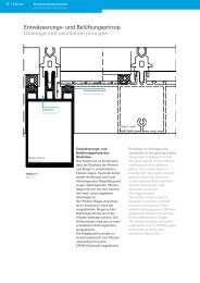
Entwässerungs- und Belüftungsprinzip<br />
Drainage and ventilation principle<br />
Eventuell auftretendes Kondensat wird durch<br />
Entwässerungsöffnungen (5 mm x 34 mm) im<br />
unteren, horizontalen Glasrahmen bzw. durch die<br />
Öffnungen in den Glasträgern des Rahmenprofils,<br />
kontrolliert nach außen geleitet. Gleichzeitig<br />
wird über diese Öffnungen der Glasfalz belüftet.<br />
Mittels Öffnungen (5 mm x 20 mm) im oberen<br />
Bereich der vertikalen Glasrahmen wird der<br />
Glasfalz entlüftet.<br />
Zur Ableitung von eventuell entstandenem<br />
Kondensat aus dem System wird die Satteldichtung<br />
in der Elementmitte auf einer Länge von<br />
10 mm ausgeschnitten.<br />
Any condensation is drained to the outside<br />
under controlled conditions through drainage<br />
slots (5 x 34 mm) in the bottom horizontal<br />
glazing frame and through the openings in the<br />
glazing supports in the frame profile. These<br />
openings are also used to ventilate the glazing<br />
rebate.<br />
The glazing rebate is ventilated by means of<br />
openings in the top of the vertical glazing frame<br />
(5 mm x 20 mm).<br />
The saddle gasket is notched to a width of<br />
10 mm in the centre of each unit to drain any<br />
condensation from the system.
Überlappendes Dichtungsprinzip<br />
Overlapping gasket design<br />
Die für die vertikale Elementkopplung benötigte<br />
Kopplungsdichtungen werden bereits in der<br />
Werkstatt montiert.<br />
Die horizontale Elementkopplung wird neben der<br />
Kopplungsdichtung über eine Satteldichtung<br />
vorgenommen, die auf der Baustelle über<br />
mehrere Elemente durchlaufend montiert wird.<br />
Die vertikalen Kopplungsdichtungen werden<br />
überlappend montiert. Die Überlappung erfolgt<br />
über die Satteldichtung (Elementaußenseite)<br />
bzw. über die horizontale Kopplungsdichtung<br />
(Elementinnenseite).<br />
Konstruktionsprinzipien<br />
Construction principles<br />
The coupling gaskets needed to connect the<br />
vertical elements are mounted in the workshop.<br />
The horizontal elements are connected using a<br />
coupling gasket and a saddle gasket that is<br />
mounted continuously across several units on<br />
the construction site.<br />
The vertical coupling gaskets are mounted so<br />
that they overlap. They overlap the saddle gasket<br />
(outside of unit) or the horizontal coupling gasket<br />
(inside of unit).<br />
Schüco | 91<br />
Schüco UCC 65 SG
92 | Schüco<br />
28 6 58<br />
Konstruktionsprinzipien<br />
Construction principles<br />
Verarbeitung und Verglasung<br />
Fabrication and glazing<br />
Verklebung 1-teilige Variante<br />
Bonding, 1-part design<br />
Maßstab 1:4<br />
Scale 1:4<br />
12<br />
131<br />
131<br />
65<br />
27 11<br />
12<br />
27<br />
65<br />
12<br />
28 6<br />
126<br />
28 6<br />
127<br />
126<br />
34<br />
13<br />
74<br />
27<br />
65
Die Verklebeeigenschaften zwischen<br />
Oberflächenbeschichtung (z. B. Dow Corning® 993<br />
/ Sikasil® SG-500) des Profiles und des Dichtstoffes<br />
sind vor Beginn der Produktion vom<br />
Dichtstofflieferanten nachzuweisen.<br />
Die Verklebeeigenschaften zwischen Oberflächen-beschichtung<br />
des Glases und Dichtstoff<br />
sind vom Glaslieferanten nachzuweisen.<br />
Die erforderliche(n) Glasdicke(n) und Scheibenrandausbildung<br />
sind mit dem Glaslieferanten<br />
abzustimmen.<br />
Die Versiegelung der Glasfuge muss mit<br />
UV-beständiger Silikon-Dichtmasse z. B. Dow<br />
Corning® 797 oder Sikasil® / WS-605-S erfolgen.<br />
Bezüglich der Haftung und Verträglichkeit mit<br />
dem Randverbund der Isolierglaseinheit sind die<br />
Verarbeitungsrichtlinien der Dichtstofflieferanten<br />
z. B. Dow Corning oder Sika Services AG zu<br />
beachten.<br />
Die Außenscheibe muss aus Einscheiben-<br />
Sicherheitsglas bestehen (die länderspezifischen<br />
Forderungen sind zu beachten).<br />
Die mit dem Glas zu verklebenden Profile<br />
werden nur in E6/C0 bis C35 und mit Signierung<br />
geliefert.<br />
Weitere Hinweise:<br />
Es dürfen nur Isoliergläser mit einer Randverklebung<br />
verwendet werden, die gegen UV-Strahlung widerstandsfähig<br />
ist. Bei Einsatz von transparentem Glas<br />
ist eine Bemusterung vor Produktionsbeginn<br />
durchzuführen (eventuell Luftblasenbildung im<br />
Bereich des Vorfüllers möglich)! Alle Kombinationen<br />
von Glas, Kleber und Vorfüller sind mit den Glas-,<br />
Kleber- und Dichtstofflieferanten abzustimmen<br />
(Gewährleistung).<br />
Konstruktionsprinzipien<br />
Construction principles<br />
The bonding properties between the surface<br />
coating (e.g. Dow Corning® 993 / Sikasil® SG-500)<br />
of the profile and the bonding compound must be<br />
documented by the sealing compound supplier<br />
before production begins.<br />
The bonding properties between the surface<br />
coating of the glass and the sealant must be<br />
documented by the glazing supplier.<br />
The necessary glass thickness and glass edge<br />
specification must be agreed with the glazing<br />
supplier.<br />
A UV-resistant silicone sealing compound, e.g.<br />
Dow Corning® 797 or Sikasil® / WS-605-S, must<br />
be used to seal the glass joint. Observe the<br />
fabrication guidelines of the sealant supplier<br />
such as Dow Corning or Sika Services AG to<br />
ensure that the sealant is compatible and bonds<br />
with the pane edge joint of the double glazed<br />
unit.<br />
The outer pane must consist of toughened safety<br />
glass (country-specific requirements must be<br />
observed).<br />
The profiles to be bonded to the glass are only<br />
supplied in E6/C0 to C35 and are date-marked.<br />
Further information:<br />
Only double-glazed units that have UV-resistant<br />
silicone edge seals may be used. When using<br />
transparent glass, samples must be taken before<br />
production starts (as air bubbles may form in the<br />
pre-filler). All combinations of glass, silicone<br />
adhesive and pre-filler should be agreed with the<br />
glass, adhesive and sealant suppliers (warranty).<br />
Schüco | 93<br />
Schüco UCC 65 SG
94 | Schüco<br />
Konstruktionsprinzipien<br />
Construction principles<br />
Verklebung 2-teilige Variante<br />
Bonding, 2-part design<br />
6 61<br />
28<br />
Maßstab 1:4<br />
Scale 1:4<br />
12<br />
135<br />
135<br />
65<br />
27 11<br />
12<br />
27 65<br />
12<br />
21<br />
12<br />
12<br />
28 6<br />
129<br />
28 6<br />
28 6<br />
28 6<br />
60<br />
130<br />
65<br />
129<br />
27 34<br />
65
Die Verklebeeigenschaften zwischen Oberflächenbeschichtung<br />
des Glases und Dichtstoff<br />
sind vom Glaslieferanten nachzuweisen.<br />
Die erforderliche(n) Glasdicke(n) und Scheibenrandausbildung<br />
sind mit dem Glaslieferanten<br />
abzustimmen.<br />
Die Versiegelung der Glasfuge muss mit<br />
UV-beständiger Silikon-Dichtmasse z. B.<br />
Dow Corning® 797 oder Sikasil® / WS-605-S<br />
erfolgen. Bezüglich der Haftung und Verträglichkeit<br />
mit dem Randverbund der Isolierglaseinheit<br />
sind die Verarbeitungsrichtlinien der Dichtstofflieferanten<br />
z. B. Dow Corning oder<br />
Sika Services AG zu beachten.<br />
Die Außenscheibe muss aus Einscheiben-<br />
Sicherheitsglas bestehen. (Die länderspezifischen<br />
Forderungen sind zu beachten).<br />
Die mit dem Glas zu verklebenden Profile<br />
werden nur in E6/C0 bis C35 und mit Signierung<br />
geliefert.<br />
Weitere Hinweise:<br />
Es dürfen nur Isoliergläser mit einer Randverklebung<br />
verwendet werden, die gegen UV-Strahlung widerstandsfähig<br />
ist. Bei Einsatz von transparentem Glas<br />
ist eine Bemusterung vor Produktions-beginn<br />
durchzuführen (eventuell Luftblasenbildung im<br />
Bereich des Vorfüllers möglich)! Alle Kombinationen<br />
von Glas, Kleber und Vorfüller sind mit den Glas-,<br />
Kleber- und Dichtstofflieferanten abzustimmen<br />
(Gewährleistung).<br />
Konstruktionsprinzipien<br />
Construction principles<br />
The bonding properties between the surface<br />
coating of the glass and the sealant must be<br />
documented by the glazing supplier.<br />
The necessary glass thickness and glass edge<br />
specification must be agreed with the glazing<br />
supplier.<br />
A UV-resistant silicone sealing compound, e.g.<br />
Dow Corning® 797 or Sikasil® / WS-605-S, must<br />
be used to seal the glass joint. Observe the<br />
fabrication guidelines of the sealant supplier<br />
such as Dow Corning or Sika Services AG to<br />
ensure that the sealant is compatible and bonds<br />
with the pane edge joint of the double glazed<br />
unit.<br />
The outer pane must consist of toughened safety<br />
glass. (country-specific requirements must be<br />
observed).<br />
The profiles to be bonded to the glass are only<br />
supplied in E6/C0 to C35 and are date-marked.<br />
Further information:<br />
Only double-glazed units that have UV-resistant<br />
silicone edge seals may be used. When using<br />
transparent glass, samples must be taken before<br />
production starts (as air bubbles may form in the<br />
pre-filler). All combinations of glass, silicone<br />
adhesive and pre-filler should be agreed with the<br />
glass, adhesive and sealant suppliers (warranty).<br />
Schüco | 95<br />
Schüco UCC 65 SG
96 | Schüco<br />
Konstruktionsprinzipien<br />
Construction principles<br />
Vordimensionierung<br />
Preliminary calculations<br />
Verklebung der Isolier-Verglasung<br />
mit dem Elementrahmen<br />
Mit Glasträger (gestützes System)<br />
With glazing support (supported system)<br />
Elementhöhe (m) / Unit height (m)<br />
4.5<br />
4.0<br />
3.5<br />
3.0<br />
2.5<br />
2.0<br />
1.5<br />
1.0<br />
0.5<br />
0.0<br />
4.5<br />
4.0<br />
3.5<br />
3.0<br />
2.5<br />
2.0<br />
1.5<br />
1.0<br />
0.5<br />
0.0<br />
0.5 1.0 1.5 2.0 2.5 3.0 3.5 4.0 4.5<br />
Elementbreite (m) / Unit width (m)<br />
Ohne Glasträger (ungestützes System)<br />
Without glazing support (non-supported system)<br />
Elementhöhe (m) / Unit height (m)<br />
Randbedingungen<br />
Parameters<br />
0.5 1.0 1.5 2.0 2.5 3.0 3.5 4.0 4.5<br />
Benennung / Description Wert / Value<br />
Elementbreite (m) / Unit width (m)<br />
Glasaufbau / Glass composition siehe Diagramm / see diagram<br />
Windsog / Negative wind load 1.000 KN/m²<br />
∆ H 220 m<br />
∆ t 20 °C<br />
∆ P max<br />
40 hPa<br />
∑ 13,2 kPa<br />
Verklebung / Bonding Dow Corning 993 / Sikasil<br />
Bonding the insulating glazing<br />
with the unit frame<br />
Unzulässiger Bereich<br />
Inadmissible range<br />
Glasträger<br />
With glazing support<br />
(supported system)
Vordimensionierung von Elementgrößen SG<br />
Für eine zielführende Nutzung dieser Diagramme<br />
müssen folgende Daten bekannt sein:<br />
Glasaufbau: Glasstärke innen / Scheibenzwischenraum<br />
/ Glasstärke außen<br />
Windsog: Produkt aus dem von der<br />
Gebäudehöhe abhängigen Staudruck<br />
und dem aerodynamischen Beiwert für<br />
den Außendruck (cPe)<br />
B (m): Breite des Elements in Metern<br />
H (m): Höhe des Elementes in Metern<br />
Klimalast, bestehend aus: *<br />
ΔH: Differenz der Ortshöhe zwischen dem<br />
Einbauort und dem Herstellungsort,<br />
ΔT: Temperaturunterschiede zwischen<br />
Einbauort (Oberflächentemperatur Glas und<br />
Rahmen) und Produktion,<br />
ΔP met : Differenz des meteorologischen Luftdrucks<br />
am Einbauort und bei der Herstellung<br />
∑: Materialkennwerte des entsprechenden<br />
Structural Glazing-Silikons<br />
(hier: Dehnungswert)<br />
Hinweise:<br />
Die Berechnung wurde auf Basis der unter<br />
„Randbedingungen“ angegebenen Werte<br />
vorgenommen und gilt nur für diese Werte.<br />
Wird in der Praxis von den o. g. Randbedingungen<br />
für die Vordimensionierung abgewichen, ergeben<br />
sich andere zulässige Isolierglasgrößen. Diese sind<br />
mit der Schüco International KG abzustimmen.<br />
Das oben dargestellte Diagramm dient<br />
ausschließlich zur Vordimensionierung.<br />
Vor der Ausführung ist objektbezogen eine exakte<br />
Dimensionierung erforderlich. Sprechen Sie die<br />
Schüco International KG an.<br />
Das dargestellte Vordimensionierungsdiagramm<br />
gibt auschließlich die technischen Einsatzgrenzen<br />
der Verklebung der Isolierglasscheibe mit dem<br />
Tragwerk der Fassade wieder. Zusätzlich sind die<br />
Einsatzgrenzen der Glasträger, T-Verbinder,<br />
Riegeldurchbiegung unter Eigenlast, Durchbiegung<br />
unter Winddruck / Windsog, Glasstatik usw.<br />
zu beachten.<br />
* Wird nur bei der Berechnung des Isolierglasrandverbundes<br />
benötigt<br />
Konstruktionsprinzipien<br />
Construction principles<br />
Preliminary structural calculations of unit size SG<br />
For effective use of these diagrams you should be<br />
aware of the following data:<br />
Glass structure: Inner glass thickness / gap<br />
between the panes / outer glass<br />
thickness<br />
Negative wind load: Product of the dynamic loading<br />
relating to building height and<br />
the aerodynamic coefficient for<br />
external pressure (cPe)<br />
B (m): Width of the unit in metres<br />
H (m): Height of the unit in metres<br />
Climate load, consisting of: *<br />
ΔH: Difference in height between the place of<br />
installation and the place of manufacture<br />
ΔT: Difference in temperature between the place<br />
of installation (surface temperature of glass<br />
and frame) and production<br />
ΔP met : Difference between the meteorological air<br />
pressure at place of installation and<br />
manufacture<br />
∑: Key values for materials for the relevant<br />
structural glazing silicone<br />
(here: expansion value)<br />
Note:<br />
The calculation will be carried out on the basis of<br />
the values given under the parameters and applies<br />
to those values only.<br />
In practice, the above dimensioning parameters<br />
will vary, giving rise to other permitted insulating<br />
glass sizes. These must be agreed with<br />
Schüco International KG.<br />
The diagram shown overleaf is intended exclusively<br />
for preliminary structural calculations. Precise<br />
calculations of the dimensions are needed for the<br />
specific project. Contact Schüco International KG.<br />
The preliminary calculation chart shown gives the<br />
technical limits for the bonding of the insulating<br />
glass pane with the load-bearing structure of the<br />
façade. The limits of use of the glazing support,<br />
T-cleats, transom deflection under glass load,<br />
deflection under positive/negative wind load and<br />
glazing load calculations etc. must also be observed.<br />
*Is only needed for calculation of insulating edge seals<br />
Schüco | 97<br />
Schüco UCC 65 SG
98 | Schüco<br />
Konstruktionsprinzipien<br />
Construction principles<br />
Maximale Glaslasten und Elementgrößen<br />
Maximum glass loads and unit sizes<br />
Einfeldraster<br />
Single module<br />
max. Elementbreite<br />
Max. unit width 1350 mm 1350 mm<br />
max. Elementhöhe<br />
Max. unit height 3600 mm 3600 mm<br />
max. Scheibengewicht<br />
Max. pane weight<br />
Doppelraster<br />
Double module<br />
250 kg<br />
150 kg<br />
150 kg<br />
max. Elementbreite<br />
Max. unit width 2700 mm 2700 mm<br />
max. Elementhöhe<br />
Max. unit height 3600 mm 3600 mm<br />
max. Scheibengewicht<br />
Max. pane weight<br />
100 kg 100 kg<br />
50 kg 50 kg<br />
50 kg 50 kg
Übersicht der Anwendungsbeispiele<br />
Overview of examples<br />
Die hier gezeigten Elementsymbole<br />
geben eine Übersicht<br />
der möglichen Bauformen. Alle<br />
auf dieser Seite angegebenen<br />
Zahlen sind Seitenzahlen zu den<br />
im Folgenden gezeigten<br />
Anwendungsbeispielen.<br />
Anwendungsbeispiele 1-teilig<br />
Example, 1-part<br />
111<br />
117<br />
118<br />
119<br />
116<br />
110<br />
101<br />
103<br />
104<br />
106<br />
108<br />
109<br />
112<br />
100<br />
102<br />
104<br />
107<br />
Anwendungsbeispiele 2-teilig<br />
Example, 2-part<br />
105<br />
The diagrams shown here provide<br />
an overview of the different<br />
shapes that are possible. The<br />
numbers below are the page<br />
numbers for the relevant<br />
examples.<br />
113<br />
114<br />
115<br />
Anwendungsbeispiele<br />
Examples<br />
106<br />
Schüco | 99<br />
Schüco UCC 65 SG
100 | Schüco<br />
Anwendungsbeispiele<br />
Examples<br />
Anwendungsbeispiele Schüco UCC 65 SG<br />
Examples for Schüco UCC 65 SG<br />
Rahmen, 1-teilig mit 12 mm Stoßfuge<br />
Frame, 1-part with 12 mm butt joint<br />
Maßstab 1:1<br />
Scale 1:1<br />
65<br />
27 11<br />
12<br />
27<br />
127<br />
28 6
12<br />
28<br />
Maßstab 1:1<br />
Scale 1:1<br />
6<br />
127<br />
Anwendungsbeispiele<br />
Examples<br />
Schüco | 101<br />
27 11 27<br />
65<br />
Schüco UCC 65 SG
102 | Schüco<br />
Anwendungsbeispiele<br />
Examples<br />
Rahmen, 1-teilig mit 21 mm Stoßfuge<br />
Frame, 1-part with 21 mm butt joint<br />
Maßstab 1:1<br />
Scale 1:1<br />
65<br />
27 11<br />
12<br />
27<br />
127<br />
28 6
21<br />
Maßstab 1:1<br />
Scale 1:1<br />
28 6<br />
127<br />
Anwendungsbeispiele<br />
Examples<br />
Schüco | 103<br />
34<br />
13<br />
27<br />
74<br />
Schüco UCC 65 SG
104 | Schüco<br />
Anwendungsbeispiele<br />
Examples<br />
Rahmen mit Kopplungsprofil, 1-teilig<br />
Frame with coupling profile, 1-part<br />
21<br />
Maßstab 1:2<br />
Scale 1:2<br />
28 6<br />
65<br />
12<br />
127<br />
28 6<br />
127<br />
74
Rahmen mit Kopplungsprofil, 2-teilig<br />
Frame with coupling profile, 2-part<br />
21<br />
Maßstab 1:2<br />
Scale 1:2<br />
28 6<br />
65<br />
12<br />
130<br />
28 6<br />
130<br />
74<br />
Anwendungsbeispiele<br />
Examples<br />
Schüco | 105<br />
Schüco UCC 65 SG
106 | Schüco<br />
Anwendungsbeispiele<br />
Examples<br />
Außensegmentierung<br />
External faceting<br />
12<br />
Maßstab 1:2<br />
Scale 1:2<br />
28<br />
6<br />
127<br />
28 6<br />
127<br />
1°<br />
65
Rahmen mit vertikaler Sprosse<br />
Frame with vertical glazing bar<br />
Maßstab 1:2<br />
Scale 1:2<br />
27<br />
127<br />
28 6<br />
65<br />
12<br />
126<br />
28 6<br />
Anwendungsbeispiele<br />
Examples<br />
27<br />
Schüco | 107<br />
Schüco UCC 65 SG
108 | Schüco<br />
Anwendungsbeispiele<br />
Examples<br />
Rahmen mit horizontaler Sprosse,<br />
horizontaler Elementstoß mit 12 mm Stoßfuge<br />
Frame with horizontal glazing bar,<br />
horizontal unit joint with 12 mm butt joint<br />
12<br />
Maßstab 1:2<br />
Scale 1:2<br />
28 6<br />
28 6<br />
127<br />
126<br />
27<br />
65<br />
27
Rahmen mit horizontaler Sprosse,<br />
horizontaler Elementstoß mit 21 mm Stoßfuge<br />
Frame with horizontal glazing bar,<br />
horizontal unit joint with 21 mm butt joint<br />
12<br />
Maßstab 1:2<br />
Scale 1:2<br />
28 6<br />
28 6<br />
127<br />
126<br />
27<br />
65<br />
34<br />
Anwendungsbeispiele<br />
Examples<br />
Schüco | 109<br />
Schüco UCC 65 SG
110 | Schüco<br />
Anwendungsbeispiele<br />
Examples<br />
Kaltbrüstung mit Einfachglas<br />
Ventilated spandrel with single glazing<br />
Maßstab 1:2<br />
Scale 1:2<br />
65 27 11 27<br />
28 6 127
Kaltbrüstung mit Einfachglas und Sprosse<br />
Ventilated spandrel with single glazing and glazing bar<br />
Maßstab 1:2<br />
Scale 1:2<br />
28 6 126<br />
65<br />
34<br />
13<br />
74<br />
27<br />
Schüco Fassade UCC 65 SG<br />
Schüco Façade UCC 65 SG<br />
Schüco | 111<br />
Schüco UCC 65 SG
112 | Schüco<br />
Anwendungsbeispiele<br />
Examples<br />
Innenliegender Sonnenschutz<br />
Internal solar shading<br />
12<br />
Maßstab 1:2<br />
Scale 1:2<br />
28 6<br />
28 6<br />
57<br />
127<br />
126<br />
35 34<br />
27<br />
65<br />
34
90° Innenecke mit Ecksprosse<br />
90° inner corner with corner glazing bar<br />
131<br />
58 6<br />
131<br />
28<br />
127 6 28<br />
12<br />
28 6 58<br />
Anwendungsbeispiele<br />
Examples<br />
65<br />
27 11<br />
12<br />
27<br />
127<br />
28 6<br />
Maßstab 1:2<br />
Scale 1:2<br />
Schüco | 113<br />
Schüco UCC 65 SG
114 | Schüco<br />
Anwendungsbeispiele<br />
Examples<br />
90° Innenecke mit 2 Sprossen<br />
90° inner corner with 2 glazing bars<br />
57 6 28<br />
127 6 28<br />
28 6 57<br />
65<br />
27 11<br />
12<br />
27<br />
127<br />
28 6<br />
Maßstab 1:2<br />
Scale 1:2
90° Außenecke mit Ecksprosse<br />
90° outer corner with corner glazing bar<br />
28<br />
Maßstab 1:2<br />
Scale 1:2<br />
28 6<br />
6<br />
127<br />
126<br />
27<br />
27 11<br />
65<br />
28 6 126<br />
Anwendungsbeispiele<br />
Examples<br />
65<br />
27 11<br />
12<br />
27<br />
127<br />
28 6<br />
Schüco | 115<br />
Schüco UCC 65 SG
116 | Schüco<br />
Anwendungsbeispiele<br />
Examples<br />
Unterer Baukörperanschluss<br />
Bottom attachment to building structure<br />
Maßstab 1:2<br />
Scale 1:2<br />
28 6 127<br />
34
Fassadenbefestigung und Kaltbrüstung mit Einfachglas<br />
Façade fixing bracket and ventilated spandrel with single glazing<br />
Maßstab 1:2<br />
Scale 1:2<br />
Anwendungsbeispiele<br />
Examples<br />
Schüco | 117<br />
Schüco UCC 65 SG
118 | Schüco<br />
Maßstab 1:4<br />
Scale 1:4<br />
Anwendungsbeispiele<br />
Examples<br />
Durchlaufträger<br />
Continuous beam
Oberer Baukörperabschluss<br />
Top attachment to building structure<br />
Maßstab 1:4<br />
Scale 1:4<br />
Anwendungsbeispiele<br />
Examples<br />
Schüco | 119<br />
Schüco UCC 65 SG
120 | Schüco<br />
Profilübersicht<br />
Overview of profiles<br />
Profilübersicht Schüco Fassade UCC 65 SG<br />
Overview of profiles for Schüco Façade UCC 65 SG<br />
Rahmenprofile, 1-teilig<br />
Frame profiles, 1-part<br />
336 540<br />
65<br />
27<br />
127<br />
127<br />
127<br />
27 27<br />
34<br />
27<br />
336 540<br />
336 540<br />
336 550<br />
336 540
Sprossenprofile, 1-teilig<br />
Glazing bar profiles, 1-part<br />
336 610<br />
336 590<br />
336 630<br />
50<br />
57<br />
200<br />
65<br />
126<br />
58<br />
65<br />
131<br />
336 700<br />
58<br />
131<br />
Profilübersicht<br />
Overview of profiles<br />
I x<br />
I y<br />
cm 4 cm 4<br />
336 540 128,71 4,25<br />
336 550 145,81 6,78<br />
336 590 195,19 65,35<br />
336 610 26,86 33,95<br />
336 630 311,13 311,08<br />
336 700 248,73 248,6<br />
Glasrahmen 1-teilig<br />
Glazing frames, 1 part<br />
23<br />
351 140<br />
351 120<br />
351 130<br />
41.4<br />
47.4<br />
23<br />
41.4<br />
47.4<br />
Maßstab 1:2<br />
Scale 1:2<br />
Schüco | 121<br />
Schüco UCC 65 SG
122 | Schüco<br />
Profilübersicht<br />
Overview of profiles<br />
Rahmenprofile, 2-teilig<br />
Frame profiles, 2-part<br />
336 810<br />
65<br />
27<br />
130<br />
127<br />
130<br />
27 27<br />
34<br />
27<br />
336 810<br />
336 810<br />
336 820<br />
336 810
Sprossenprofile, 2-teilig<br />
Glazing bar profile, 2-part<br />
336 850<br />
336 840<br />
336 870<br />
50<br />
60<br />
177.5<br />
65<br />
129<br />
61<br />
65<br />
135<br />
336 880<br />
61<br />
135<br />
Profilübersicht<br />
Overview of profiles<br />
I x<br />
I y<br />
cm 4 cm 4<br />
336 810 137,99 4,32<br />
336 820 155,39 6,89<br />
336 840 223,96 70,11<br />
336 850 31,39 38,71<br />
336 870 326,51 326,54<br />
336 880 285,7 285,68<br />
Glasrahmen 2-teilig<br />
Glazing frames, 2 part<br />
29<br />
351 150<br />
336 970<br />
336 980<br />
34.4<br />
40.4<br />
29<br />
Adapterprofil<br />
Adapter profile<br />
5.2<br />
336 830<br />
15.8<br />
34.4<br />
40.4<br />
Maßstab 1:2<br />
Scale 1:2<br />
Schüco | 123<br />
Schüco UCC 65 SG