Concrete Plant + Precast Technology Betonwerk + Fertigteil-Technik
Concrete Plant + Precast Technology Betonwerk + Fertigteil-Technik
Concrete Plant + Precast Technology Betonwerk + Fertigteil-Technik

Erfolgreiche ePaper selbst erstellen
Machen Sie aus Ihren PDF Publikationen ein blätterbares Flipbook mit unserer einzigartigen Google optimierten e-Paper Software.
Produktion<br />
1<br />
the manhole element design. For this purpose, the<br />
complex control unit transfers the required data to the<br />
saw used. At each saw, the plant operator sees on a<br />
touchscreen which drain element has to be cut from<br />
which basic element type, and the manhole base section<br />
position number to which this individual piece is<br />
to be allocated. A table is used to join the prefabricated<br />
individual pieces and to bond them together using a<br />
glue gun.<br />
This working table has a circle drawn on its surface<br />
that is equivalent to the inside diameter of the base section,<br />
together with a gon scale so that the manufacturing<br />
of the positions of the individual inlets and outlets<br />
can be visually inspected. To check the drain layout, a<br />
laser system has been installed above the table that<br />
projects the center axes of the drains onto the table.<br />
This is just another possibility to monitor the position<br />
of the drains.<br />
In addition, these negative forms are fitted with the<br />
connecting elements, which, in turn, are fitted with appropriate<br />
rubber seals if required. As a result, the final<br />
form can be adapted to any type of connecting pipe<br />
(stoneware, concrete etc.). Each blockout element manufactured<br />
in this process is given the position number<br />
of the relevant manhole, and subsequently kept on<br />
stock in an interim storage area.<br />
Formwork preparation<br />
At the Teising production facility, about 100 steel forms<br />
are available, which are prepared to accommodate the<br />
production of one day (one-shift operation), filled with<br />
concrete and stored for curing. The formwork is<br />
removed from the elements after a storage period of 24<br />
hours, i.e. on the day following production. In theory,<br />
the form could also be removed after about seven or<br />
eight hours, which would enable two-shift operation.<br />
The steel formwork of a manhole base section consists<br />
of two spherical shells mounted on a formwork<br />
platform. The manhole is produced in a position turned<br />
by 180 degrees compared to final assembly, i.e. upsidedown.<br />
The inner core is designed as an expanding element,<br />
and a rubber liner is applied to it in order to<br />
achieve an even better surface quality.<br />
The inner core of the form is cone-shaped, and the<br />
blockout element is cut to size obliquely at the surface<br />
of the final manhole element. This ensures the required<br />
inclination of the base section. The prefabricated blockout<br />
element is mounted on top of the inner core and<br />
held in place by centering pieces.<br />
The joints between the blockout element and the<br />
steel form are also masked off in order to avoid the occurrence<br />
of any unwanted edge during the following<br />
process steps. This would not necessarily be required<br />
but has become a routine procedure at Haba Beton for<br />
quality reasons.<br />
When preparing the formwork, a touchscreen<br />
makes the system easy to control for the operator: The<br />
relevant base section is shown as scheduled in the production<br />
sequence so that any possibility of confusion is<br />
excluded. This step provides an additional opportunity<br />
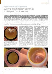
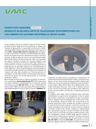
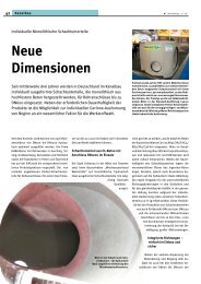
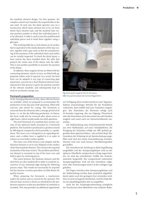
Fig. 6 Joining the negative form for the drains.<br />
Abb. 6 Zusammensetzen der Gerinne-Negativform.<br />
zur Verfügung; diese werden jeweils in einer Tagesproduktion<br />
(einschichtiger Betrieb) für die Produktion<br />
vorbereitet, dann befüllt und zum Aushärten eingelagert.<br />
Das Entschalen der Elemente erfolgt nach<br />
24 Stunden Lagerung, also am Folgetag. Theoretisch<br />
wäre das Entschalen nach etwa sieben bis acht Stunden<br />
möglich und somit auch ein Zweischichtbetrieb umsetzbar.<br />
Die Stahlschalung eines Schachtunterteils besteht<br />
aus zwei Halbschalen auf einer Schalplattform, die<br />
Fertigung des Schachtes erfolgt um 180° gedreht gegenüber<br />
dem späteren Einbau – also auf dem Kopf. Der<br />
Innenkern der Schalung ist als Spreizschalung ausgeführt<br />
und wird mit einem Gummiüberzug versehen.<br />
Hiermit wird eine noch bessere Oberflächenqualität<br />
geschaffen.<br />
Der Innenkern der Schalung ist dabei kegelförmig<br />
ausgebildet und der Aussparungskörper wird an der<br />
späteren Oberfläche entsprechend schräg zugeschnitten.<br />
So wird das erforderliche Gefälle des Schachtunterteils<br />
hergestellt. Der entsprechend vorbereitete<br />
Aussparungskörper wird auf den Innenkern aufgesetzt,<br />
über Zentrierungen wird er in der richtigen Lage<br />
gehalten.<br />
Die Fugen zwischen dem Aussparungskörper und<br />
der Stahlschalung werden dann zusätzlich abgeklebt,<br />
damit später auch der geringste Grat vermieden wird.<br />
Dies ist nicht zwingend erforderlich, wird bei Haba Beton<br />
aus Qualitätsgründen aber so ausgeführt.<br />
Auch bei der Schalungsvorbereitung ermöglicht<br />
ein Touchscreen dem Mitarbeiter eine einfache Bedie-<br />
5