Technische Information (PDF, 818 KB)
Technische Information (PDF, 818 KB)
Technische Information (PDF, 818 KB)

Erfolgreiche ePaper selbst erstellen
Machen Sie aus Ihren PDF Publikationen ein blätterbares Flipbook mit unserer einzigartigen Google optimierten e-Paper Software.
BETAflam ®<br />
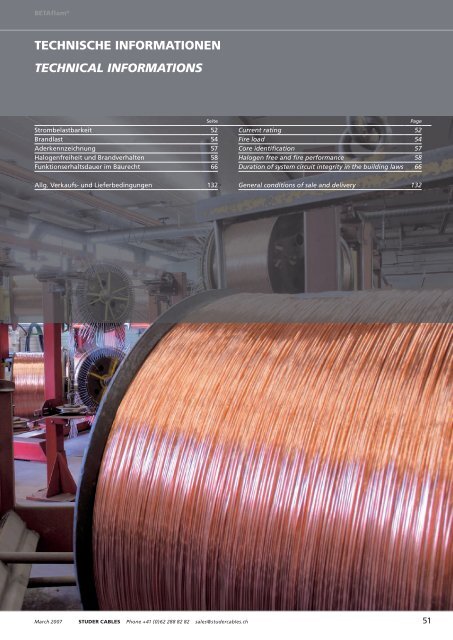
TECHNISCHE INFORMATIONEN<br />
TECHNICAL INFORMATIONS<br />
Seite<br />
Strombelastbarkeit 52<br />
Brandlast 54<br />
Aderkennzeichnung 57<br />
Halogenfreiheit und Brandverhalten 58<br />
Funktionserhaltsdauer im Baurecht 66<br />
Page<br />
Current rating 52<br />
Fire load 54<br />
Core identification 57<br />
Halogen free and fire performance 58<br />
Duration of system circuit integrity in the building laws 66<br />
Allg. Verkaufs- und Lieferbedingungen 132<br />
General conditions of sale and delivery 132<br />
March 2007 STUDER CABLES Phone +41 (0)62 288 82 82 sales@studercables.ch 51
<strong>Technische</strong> <strong>Information</strong>en<br />
Technical informations<br />
STROMBELASTBARKEIT<br />
CURRENT RATINGS<br />
MEHRLEITERKABEL, LEITERTEMPERATUR MAX. 70 ºC<br />
mit Kupferleiter, Umgebungstemperatur 30 ºC<br />
MULTICORE CABLES, CONDUCTOR TEMPERATURE MAX. 70 ºC<br />
with copper conductors, ambient temperature 30 ºC<br />
Kabelaufbau<br />
Construction<br />
Verlegeart A<br />
Kabel in Rohr<br />
in gedämmter Wand<br />
Mode of laying A<br />
Cables in tubes<br />
in insulated walls<br />
Verlegeart B<br />
In Rohren auf oder unter Putz<br />
oder geschlossenen Kanälen<br />
Mode of laying B<br />
In tubes, on or in wall<br />
or in closed conduits<br />
Verlegeart C<br />
Kabel offen auf Trasse verlegt,<br />
oder Einzelbefestigung<br />
Mode of laying C<br />
Clipped direct or laid<br />
in open troughs or ducts<br />
Verlegeart E<br />
Offen auf gelochten Trassen<br />
oder frei in Luft<br />
Mode of laying E<br />
Open laying on perforated trays<br />
or in air<br />
Anzahl belastete Adern / Number of energized cores<br />
2 3 2 3 2 3 2 3<br />
mm² A A A A A A A A<br />
1,5 15 13 16 15 19 17 22 18<br />
2,5 18 17 23 20 27 24 30 25<br />
4 25 23 30 27 36 32 40 34<br />
6 32 29 38 34 46 41 51 43<br />
10 43 39 52 46 63 57 70 60<br />
16 57 52 69 62 85 76 94 80<br />
25 75 68 90 80 112 96 119 101<br />
35 92 83 111 99 138 119 148 126<br />
50 110 99 133 118 168 144 180 153<br />
70 139 125 168 149 213 184 232 196<br />
95 167 150 201 179 258 223 282 238<br />
120 192 172 232 206 299 259 328 276<br />
150 219 223 258 225 344 299 379 319<br />
185 248 245 294 255 392 341 434 364<br />
240 291 261 344 297 461 403 514 430<br />
Angaben gelten für Dauerbetrieb.<br />
Für abweichende Verlegebedingungen (Häufung, abweichende Umgebungstemperaturen,<br />
andere Belastungsgrade, vieladrige Kabel) müssen Korrekturfaktoren<br />
berücksichtigt werden.<br />
Valid for continuous operation.<br />
For operating conditions different from the above, corrective factors must be<br />
taken into account (multiple cables, other load factors, ambient temperatures or<br />
multicore cables).<br />
EINLEITERKABEL, LEITERTEMPERATUR MAX. 70 ºC<br />
mit Kupferleiter, Umgebungstemperatur 30 ºC<br />
SINGLE CORE CABLES, CONDUCTOR TEMPERATURE MAX. 70 ºC<br />
with copper conductors, ambient temperature 30 ºC<br />
Kabelaufbau<br />
Construction<br />
Verlegeart A1<br />
Kabel in Rohr<br />
in gedämmter Wand<br />
Mode of laying A1<br />
Cables in tubes<br />
in insulated walls<br />
Verlegeart B1<br />
In Rohren auf oder unter Putz<br />
oder geschlossenen Kanälen<br />
Mode of laying B1<br />
In tubes, on or in wall<br />
or in closed conduits<br />
Verlegeart C<br />
Kabel offen auf Trasse verlegt,<br />
oder Einzelbefestigung<br />
Mode of laying C<br />
Clipped direct or laid<br />
in open troughs or ducts<br />
Verlegeart F<br />
Offen auf gelochten Trassen<br />
oder frei in Luft<br />
Mode of laying F<br />
Open laying on perforated trays<br />
or in air<br />
Anzahl belastete Adern / Number of energized cores<br />
2 3 2 3 2 3 2 3<br />
mm² A A A A A A A A<br />
240 320 286 400 346 461 403 546 485<br />
300 367 328 458 394 530 464 629 561<br />
400 396 355 500 434 580 524 754 656<br />
500 432 387 536 477 638 580 868 749<br />
Angaben gelten für Dauerbetrieb.<br />
Für abweichende Verlegebedingungen (Häufung, abweichende Umgebungstemperaturen,<br />
andere Belastungsgrade, vieladrige Kabel) müssen Korrekturfaktoren<br />
berücksichtigt werden.<br />
Valid for continuous operation.<br />
For operating conditions different from the above, corrective factors must be<br />
taken into account (multiple cables, other load factors, ambient temperatures or<br />
multicore cables).<br />
52 Studer Services Telefon +49 (0)6158 9208 0 info@studerservices.de März 2007
<strong>Technische</strong> <strong>Information</strong>en<br />
Strombelastbarkeit<br />
Technical informations<br />
Current ratings<br />
MEHRLEITERKABEL, LEITERTEMPERATUR MAX. 90 ºC<br />
mit Kupferleiter, Umgebungstemperatur 30 ºC<br />
MULTICORE CABLES, CONDUCTOR TEMPERATURE MAX. 90 ºC<br />
with copper conductors, ambient temperature 30 ºC<br />
Kabelaufbau<br />
Construction<br />
Verlegeart A<br />
Kabel in Rohr<br />
in gedämmter Wand<br />
Mode of laying A<br />
Cables in tubes<br />
in insulated walls<br />
Verlegeart B<br />
In Rohren auf oder unter Putz<br />
oder geschlossenen Kanälen<br />
Mode of laying B<br />
In tubes, on or in wall<br />
or in closed conduits<br />
Verlegeart C<br />
Kabel offen auf Trasse verlegt,<br />
oder Einzelbefestigung<br />
Mode of laying C<br />
Clipped direct or laid<br />
in open troughs or ducts<br />
Verlegeart E<br />
Offen auf gelochten Trassen<br />
oder frei in Luft<br />
Mode of laying E<br />
Open laying on perforated trays<br />
or in air<br />
Anzahl belastete Adern / Number of energized cores<br />
2 3 2 3 2 3 2 3<br />
mm² A A A A A A A A<br />
1,5 18 16 22 19 24 22 26 23<br />
2,5 25 22 30 26 33 30 36 32<br />
4 33 30 40 35 45 40 49 42<br />
6 42 38 51 44 58 52 63 54<br />
10 57 51 69 60 80 71 86 75<br />
16 76 68 91 80 107 96 115 100<br />
25 99 89 119 105 138 119 149 127<br />
35 121 109 146 128 171 147 185 158<br />
50 145 130 175 154 209 179 225 192<br />
70 183 164 221 194 269 229 289 246<br />
95 220 197 265 233 328 278 352 298<br />
120 253 227 305 268 382 322 410 346<br />
150 290 259 334 300 441 371 473 399<br />
185 329 295 384 340 506 424 542 456<br />
240 386 346 459 398 599 500 641 538<br />
Angaben gelten für Dauerbetrieb.<br />
Für abweichende Verlegebedingungen (Häufung, abweichende Umgebungstemperaturen,<br />
andere Belastungsgrade, vieladrige Kabel) müssen Korrekturfaktoren<br />
berücksichtigt werden.<br />
Valid for continuous operation.<br />
For operating conditions different from the above, corrective factors must be<br />
taken into account (multiple cables, other load factors, ambient temperatures or<br />
multicore cables).<br />
EINLEITERKABEL, LEITERTEMPERATUR MAX. 90 ºC<br />
mit Kupferleiter, Umgebungstemperatur 30 ºC<br />
SINGLE CORE CABLES, CONDUCTOR TEMPERATURE MAX. 90 ºC<br />
with copper conductors, ambient temperature 30 ºC<br />
Kabelaufbau<br />
Construction<br />
Verlegeart A1<br />
Kabel in Rohr<br />
in gedämmter Wand<br />
Mode of laying A1<br />
Cables in tubes<br />
in insulated walls<br />
Verlegeart B1<br />
In Rohren auf oder unter Putz<br />
oder geschlossenen Kanälen<br />
Mode of laying B1<br />
In tubes, on or in wall<br />
or in closed conduits<br />
Verlegeart C<br />
Kabel offen auf Trasse verlegt,<br />
oder Einzelbefestigung<br />
Mode of laying C<br />
Clipped direct or laid<br />
in open troughs or ducts<br />
Verlegeart F<br />
Offen auf gelochten Trassen<br />
oder frei in Luft<br />
Mode of laying F<br />
Open laying on perforated trays<br />
or in air<br />
Anzahl belastete Adern / Number of energized cores<br />
2 3 2 3 2 3 2 3<br />
mm² A A A A A A A A<br />
240 424 380 528 450 599 500 679 607<br />
300 486 435 603 514 693 576 783 703<br />
400 538 478 690 584 783 670 940 823<br />
500 580 516 749 645 852 760 1083 946<br />
Angaben gelten für Dauerbetrieb.<br />
Für abweichende Verlegebedingungen (Häufung, abweichende Umgebungstemperaturen,<br />
andere Belastungsgrade, vieladrige Kabel) müssen Korrekturfaktoren<br />
berücksichtigt werden.<br />
Valid for continuous operation.<br />
For operating conditions different from the above, corrective factors must be<br />
taken into account (multiple cables, other load factors, ambient temperatures or<br />
multicore cables).<br />
March 2007 STUDER CABLES Phone +41 (0)62 288 82 82 sales@studercables.ch 53
<strong>Technische</strong> <strong>Information</strong>en<br />
Technical informations<br />
BRANDLAST<br />
FIRE LOAD<br />
BETAflam ® SICHERHEITS- UND INSTALLATIONSKABEL<br />
BETAflam ® SAFETY AND INSTALLATION CABLES<br />
Kabelaufbau<br />
Construction<br />
NHXH<br />
FE180/<br />
E30, E60, E90<br />
NHXCH<br />
FE180/<br />
E30, E60, E90<br />
N2XH N2XCH NHXMH<br />
300/500 V<br />
FE0 FE5 FE180/E30 FE180/<br />
E30-CLE<br />
n × mm² kWh / m kWh / m kWh / m kWh / m kWh / m kWh / m kWh / m kWh / m kWh / m<br />
1 × 4 … 0,26 0,17 0,42 0,12 0,16 0,11 0,37<br />
1 × 6 … 0,28 0,18 0,44 0,15 0,20 0,13 0,41<br />
1 × 10 … 0,32 0,21 0,53 0,20 0,25 0,17 0,49<br />
1 × 16 … 0,38 0,29 0,64 0,32 0,38 0,23 0,60<br />
1 × 25 … 0,48 0,39 0,45 0,42 0,33 0,76<br />
1 × 35 … 0,53 0,46 0,56 0,57 0,41 0,89<br />
1 × 50 … 0,65 0,53 0,65 0,66 0,52 1,06<br />
1 × 70 … 0,75 0,55 0,92 0,88 0,68 1,30<br />
1 × 95 … 0,96 0,63 1,15 1,10 0,92 1,62<br />
1 × 120 … 1,08 0,72 1,35 1,30 1,07 1,83<br />
1 × 150 … 1,26 0,90 1,58 1,56 1,24 2,07<br />
1 × 185 … 1,52 1,08 1,91 1,84 1,49 2,39<br />
1 × 240 … 1,84 1,22 2,32 2,23 1,82 2,82<br />
1 × 300 … 2,25 1,32 2,94 2,83 2,31 3,45<br />
1 × 400 … 2,95<br />
1 × 500 … 3,47<br />
2 × 1,5 … 0,65 1,10 0,44 0,36 0,16 0,21 0,26 0,61<br />
2 × 2,5 … 0,71 1,29 0,49 0,42 0,21 0,26 0,31 0,70<br />
2 × 4 … 0,78 1,44 0,31 0,37 0,31 0,71<br />
2 × 6 … 0,77 1,51 0,44 0,48 0,39 0,83<br />
2 × 10 … 0,90 1,73 0,59 0,62 0,57 1,07<br />
2 × 16 … 1,06 0,97 0,79 1,42<br />
2 × 25 … 1,48 1,39 1,11 1,86<br />
3 × 1,5 … 0,59 1,11 0,48 0,48 0,42 0,20 0,25 0,23 0,60<br />
3 × 2,5 … 0,65 1,11 0,56 0,55 0,47 0,26 0,31 0,28 0,68<br />
3 × 4 … 0,71 1,23 0,65 0,64 0,61 0,32 0,37 0,29 0,70<br />
3 × 6 … 0,77 1,34 0,73 0,72 0,78 0,41 0,46 0,38 0,85<br />
3 × 10 … 0,88 1,54 0,86 0,85 1,10 0,58 0,62 0,52 1,06<br />
3 × 16 … 1,29 2,13 1,19 1,18 1,15 0,74 1,40<br />
3 × 25 … 1,68 3,00 1,65 1,59 1,71 1,01 1,80<br />
3 × 35 … 1,90 3,24 1,95 1,91 1,91 1,56 2,45<br />
3 × 50 … 2,42 4,20 2,31 2,27 2,39 2,11 3,12<br />
3 × 70 … 2,91 5,03 3,31 2,79 3,97<br />
3 × 95 … 3,54 6,13<br />
3 × 120 … 4,02 4,31<br />
3 × 150 … 4,95 9,92<br />
3 × 185 … 5,93 10,26<br />
3 × 240 … 7,52 12,69<br />
3 × 25 +16 … 1,93 1,33 2,20<br />
3 × 35 +16 … 2,22 1,79 2,77<br />
3 × 50 + 25 … 2,83 2,54 3,67<br />
3 × 70 + 35 … 3,40 3,42 4,73<br />
3 × 95 + 50 … 4,50 4,55 6,31<br />
3 × 120 +70 … 4,93 5,19 7,13<br />
3 × 150 +70 … 5,89 6,01 7,83<br />
3 × 185 + 95 … 7,24 7,24 10,03<br />
3 × 240 +120 … 8,76 9,32 12,47<br />
54 Studer Services Telefon +49 (0)6158 9208 0 info@studerservices.de März 2007
<strong>Technische</strong> <strong>Information</strong>en<br />
Brandlast<br />
Technical informations<br />
Fire load<br />
Kabelaufbau<br />
Construction<br />
NHXH<br />
FE180/<br />
E30, E60, E90<br />
NHXCH<br />
FE180/<br />
E30, E60, E90<br />
N2XH N2XCH NHXMH<br />
300/500 V<br />
FE0 FE5 FE180/E30 FE180/<br />
E30-CLE<br />
n × mm² kWh / m kWh / m kWh / m kWh / m kWh / m kWh / m kW h/ m kWh / m kWh / m<br />
4 × 1,5 … 0,73 0,78 0,54 0,54 0,47 0,25 0,30 0,29 0,68<br />
4 × 2,5 … 0,79 1,24 0,63 0,62 0,56 0,34 0,40 0,36 0,79<br />
4 × 4 … 0,88 1,39 0,73 0,72 0,78 0,41 0,46 0,36 0,80<br />
4 × 6 … 0,97 1,55 0,82 0,82 0,94 0,54 0,57 0,45 0,94<br />
4 × 10 … 1,01 1,16 0,99 1,00 1,30 0,77 0,78 0,64 1,23<br />
4 × 16 … 1,38 1,45 1,43 1,37 1,80 1,27 1,28 0,91 1,63<br />
4 × 25 … 2,03 2,21 1,97 1,94 2,60 1,84 2,06 1,37 2,23<br />
4 × 35 … 2,35 3,76 2,31 2,27 3,10 2,25 2,44 1,93 2,91<br />
4 × 50 … 3,01 4,79 2,89 2,77 3,08 2,97 2,62 3,75<br />
4 × 70 … 3,63 5,75 3,00 4,43 4,28 3,55 4,86<br />
4 × 95 … 4,66 7,24 3,90 5,54 5,35 4,72 6,48<br />
4 × 120 … 5,10 5,42 4,77 6,53 5,34 7,28<br />
4 × 150 … 6,19 6,53 6,81 7,38 6,50 9,06<br />
4 × 185 … 7,57 7,98 9,04 7,46 10,25<br />
4 × 240 … 9,47 9,93 11,03 9,64 13,65<br />
5 × 1,5 … 0,89 0,62 0,56 0,31 0,35 0,36 0,79<br />
5 × 2,5 … 0,97 0,70 0,64 0,43 0,45 0,45 0,92<br />
5 × 4 … 1,04 0,82 0,98 0,51 0,52 0,46 0,94<br />
5 × 6 … 1,15 0,91 1,10 0,67 0,65 0,58 1,12<br />
5 × 10 … 1,31 1,11 1,50 0,99 0,90 0,81 1,45<br />
5 × 16 … 1,66 1,68 2,20 1,57 1,48 1,23 2,04<br />
5 × 25 … 2,14 2,35 3,10 2,32 2,09 1,68 2,68<br />
5 × 35 … 2,87 2,81 2,88 2,95 2,55 3,63<br />
5 × 50 … 3,69 3,42 3,77 3,46 3,25 4,50<br />
5 × 70 … 4,41 5,45 5,01 4,30 6,00<br />
5 × 95 … 5,77 7,05 6,42 5,79 7,74<br />
5 × 120 … 6,77<br />
7 × 1,5 … 1,00 1,05 0,51 5,00 0,64 0,38 0,43 0,39 0,85<br />
7 × 2,5 … 1,09 1,14 0,58 0,57 0,81 0,51 0,56 0,50 1,01<br />
7 × 4 … 1,21 1,27 0,61 0,64 0,52 1,04<br />
12 × 1,5 … 1,51 1,56 0,76 0,74 0,63 0,64 0,57 1,04<br />
12 × 2,5 … 1,66 1,72 0,88 0,86 0,84 0,73 1,26<br />
19 × 1,5 … 2,12 1,05 1,02 0,92 0,90 0,94 1,61<br />
19 × 2,5 … 2,33 1,21 1,19 1,26 1,22 1,98<br />
24 × 1,5 … 2,66 2,77 1,31 1,25 1,15 1,12 1,18 1,86<br />
24 × 2,5 … 2,99 3,06 1,53 1,47 1,44 2,20<br />
30 × 1,5 … 3,16 3,28 1,54 1,47 1,42 1,37<br />
30 × 2,5 … 3,56 3,69 1,80 1,77<br />
1 kWh = 3,6 MJ<br />
Die Angaben sind Richtwerte<br />
1 kWh = 3,6 MJ<br />
Nominal figures only<br />
March 2007 STUDER CABLES Phone +41 (0)62 288 82 82 sales@studercables.ch 55
<strong>Technische</strong> <strong>Information</strong>en<br />
Brandlast<br />
Technical informations<br />
Fire load<br />
BETAflam ® SIGNALKABEL UND BRANDMELDEKABEL<br />
BETAflam ® SIGNAL CABLES AND FIRE ALARM CABLES<br />
Kabelaufbau<br />
Construction<br />
JE-H(St)H<br />
FE180 /<br />
E30, E60, E90<br />
JE-H(St)HRH<br />
FE180<br />
armiert/<br />
armoured<br />
Kabelaufbau<br />
Construction<br />
J-H(St)H<br />
J-H(St)H<br />
0,6 mm 0,8 mm <br />
n × 2 × mm kWh / m kWh / m n × 2 × … kWh / m kWh / m<br />
1 × 2 × 0,8 0,15 0,34<br />
2 × 2 × 0,8 0,20 0,41 2 × 2 × … 0,15 0,17<br />
4 × 2 × 0,8 0,33 0,66 4 × 2 × … 0,23 0,27<br />
6 × 2 × … 0,26 0,31<br />
8 × 2 × 0,8 0,64 1,22<br />
10 × 2 × … 0,34 0,42<br />
12 × 2 × 0,8 0,81 1,45<br />
16 × 2 × 0,8 1,02 1,85<br />
20 × 2 × 0,8 1,24 2,12 20 × 2 × … 0,55 0,70<br />
30 × 2 × … 0,69 0,96<br />
32 × 2 × 0,8 2,15 3,69<br />
40 × 2 × 0,8 2,45 4,10 40 × 2 × … 0,83 1,17<br />
50 × 2 × … 1,04 1,38<br />
52 × 2 × 0,8 3,04 4,82<br />
80 × 2 × 0,8 4,23 6,15<br />
100 × 2 × 0,8 5,22 7,33 100 × 2 × … 1,90 2,66<br />
1 × 2 × 1,5 mm² 0,20<br />
2 × 2 × 1,5 mm² 0,27<br />
1 × 2 × 2,5 mm² 0,23<br />
1 kWh = 3,6 MJ<br />
Die Angaben sind Richtwerte<br />
1 kWh = 3,6 MJ<br />
Nominal figures only<br />
56 Studer Services Telefon +49 (0)6158 9208 0 info@studerservices.de März 2007
<strong>Technische</strong> <strong>Information</strong>en<br />
Technical informations<br />
ADERKENNZEICHNUNG NACH HD 308 S2<br />
CORE IDENTIFICATION ACC. TO HD 308 S2<br />
KABEL MIT GRÜN-GELBER ADER<br />
Ader<br />
Anzahl<br />
Aderfunktion<br />
Aderfarbe<br />
1 PE grün-gelb<br />
2<br />
3 LNPE braun, blau, grün-gelb<br />
4 3LPE braun, schwarz, grau, grün-gelb<br />
5 3LNPE braun, schwarz, grau, blau, grün-gelb<br />
6 NRPE schwarz, nummeriert, grün-gelb<br />
CABLES WITH GREEN-YELLOW CONDUCTOR<br />
Core<br />
numbers<br />
Core<br />
function<br />
Core<br />
colour<br />
1 PE green-yellow<br />
2<br />
3 LNPE brown, blue, green-yellow<br />
4 3LPE brown, black, grey, green-yellow<br />
5 3LNPE brown, black, grey, blue, green-yellow<br />
6 NRPE black, numbered, green-yellow<br />
KABEL OHNE GRÜN-GELBE ADER,<br />
KABEL MIT KONZENTRISCHEM AUSSENLEITER<br />
Ader<br />
Anzahl<br />
Aderfunktion<br />
Aderfarbe<br />
1 L schwarz<br />
2 LN braun, blau<br />
3 3L braun, schwarz, grau<br />
4 3LN braun, schwarz, grau, blau<br />
5<br />
6 NR schwarz, nummeriert<br />
CABLES WITHOUT GREEN-YELLOW CONDUCTOR,<br />
CABLES WITH CONCENTRIC CONDUCTOR<br />
Core<br />
numbers<br />
Core<br />
function<br />
Core<br />
colour<br />
1 L black<br />
2 LN brown, blue<br />
3 3L brown, black, grey<br />
4 3LN brown, black, grey, blue<br />
5<br />
6 NR black, numbered<br />
March 2007 STUDER CABLES Phone +41 (0)62 288 82 82 sales@studercables.ch 57
<strong>Technische</strong> <strong>Information</strong>en<br />
Technical informations<br />
HALOGENFREIHEIT UND BRANDVERHALTEN<br />
HALOGEN FREE AND FIRE PERFORMANCE<br />
HALOGENFREIHEIT<br />
Als Halogene bezeichnet man die Elemente der Gruppe 7 im<br />
Periodensystem: Chlor (Cl), Fluor (F), Brom (Br), Jod (I).<br />
Halogenfreie Kabel sind frei von all diesen Elementen.<br />
Sie werden Halogene genannt, weil sie mit Laugen zusammen<br />
Salze bilden (Hals: griechisch für Salz); Chlor bildet mit Natrium<br />
Kochsalz (NaCl).<br />
Die Halogene bilden einen Bestandteil vieler Säuren<br />
HCl = Salzsäure<br />
HF = Hydrogenfluorid<br />
HBr = Hydrogenbromid<br />
Der weitest verbreitete halogenhaltige Kunststoff ist PVC (Polyvinylchlorid).<br />
Im Brandfall wird Salzsäure abgespalten. Daher<br />
besteht die Tendenz, halogenhaltige Kunststoffe durch<br />
halogenfreie zu ersetzen. So wird beispielsweise PVC in grossem<br />
Masse durch Polyolefine ersetzt, wie zum Beispiel Polyäthylen.<br />
Dank halogenfreier Kabel verhindert man das Entstehen von<br />
korrosiven und giftigen Gasen.<br />
Prüfverfahren<br />
1000 mg Material werden auf einem vorher ausgeglühten<br />
Kupferdraht an den äusseren Rand einer Gasflamme gehalten.<br />
Anforderung<br />
Der Werkstoff gilt als halogenfrei, wenn keine grüne bis blaugrüne<br />
Verfärbung der Flamme auftritt.<br />
Chlor und Brom verfärben die Flamme, Fluor kann nicht sicher<br />
nach gewiesen werden.<br />
Prüfnorm<br />
IEC 60754-1, EN 50267-2-1<br />
HALOGEN FREE<br />
The halogens are the elements of the 7th group in the Periodic<br />
Table of Elements: chlorine (Cl), fluorine (F), bromine (Br),<br />
iodine (I).<br />
Halogen free cables must be free of chlorine, fluorine and bromine<br />
(PVC cables contain halogen, PVC = Polyvinylchloride).<br />
The halogens are an integrated component of many acids<br />
HCl = Salt acid (hydrochloric acid)<br />
HF = Hydrogenfluorid<br />
HBr = Hydrogenbromid<br />
The most popular plastic containing halogens is PVC (polyvinylchloride).<br />
In case of fire or at high temperature PVC starts to<br />
degradate. Hydrochloric acid and other fission products are<br />
generated and leads to extremely aggressive corrosion. Therefore<br />
the current trend is to replace the halogen containing plastics<br />
with halogen free ones. For instance PVC is currently being<br />
replaced at a large scale with polyolefin i.e. polyethylene.<br />
Thanks to halogen free cables the formation of corrosive and<br />
toxic gases can be prevented.<br />
Test procedures<br />
1000 mg of the testing material must be hold at one termination<br />
of an pre-annealed copper wire in a gas flame.<br />
Requirement<br />
The material is considered to be halogen free if no green to<br />
blue-green flame discolouration occurs. The chlorine and the<br />
bromine would cause such a discolouration, however the existence<br />
of fluorine cannot be proven like that.<br />
Test standards<br />
IEC 60754-1, EN 50267-2-1<br />
58 Studer Services Telefon +49 (0)6158 9208 0 info@studerservices.de März 2007
<strong>Technische</strong> <strong>Information</strong>en<br />
HALOGENFREIHEIT UND BRANDVERHALTEN<br />
Technical informations<br />
HALOGEN FREE AND FIRE PERFORMANCE<br />
KORROSIVITÄT DER BRANDGASE<br />
Korrosiv wirkende Gase verbinden sich mit der Feuchtigkeit zu<br />
aggressiven Säuren, die Metallteile angreifen und hier, selbst<br />
bei geringem direkten Brandschaden, grosse Folgeschäden verursachen.<br />
Dies betrifft auch nicht direkt vom Brandereignis<br />
betroffene Stellen. Besonders gefährdet sind elektrische Kontakte,<br />
elektronische Bauteile und Apparate, Maschinen und<br />
Metallkonstruktionen. Sogar das von Beton eingeschlossene<br />
Armierungseisen wird angegriffen.<br />
Prüfverfahren<br />
1000 mg Isoliermaterial wird in einem Verbrennungsofen bei<br />
935 °C mit definierter Luftzufuhr verbrannt ( 30 min). Mit<br />
zwei Gaswasch flaschen im Abluftstrom wird die Leitfähigkeit<br />
und der pH-Wert gemessen. Damit lassen sich schon geringe<br />
Mengen halogenhaltiger Stoffe nachweisen.<br />
Die Prüfung ist bestanden, wenn<br />
der pH-Wert > 4,3<br />
die Leitfähigkeit < 10 µS/mm<br />
betragen.<br />
Prüfnorm<br />
IEC 60754-2, EN 50267-2-2<br />
DEGREE OF ACIDITY OF COMBUSTION GASES<br />
Corrosive gases act with moisture to produce aggressive acids<br />
which corrode metal parts and cause extensive long-term damage,<br />
eben though the fire damage may only be limited; this is<br />
because corrosive gases often spread throughout a building<br />
through the ventilation system or withing whole installations.<br />
The damage may not be limited to the area immediately affected<br />
by the fire. Electronic units and electronic contacts are particularly<br />
vulnerable, as are free-standing or concrete encolsed<br />
steel constructions.<br />
Test procedures<br />
1000 mg insulation material is burned in a combustion furnace<br />
at 935 °C with pre-defined air supply for over 30 minutes.<br />
By means of two gas washing containers, held in the airflow<br />
the conductivity and the pH-value are measured. Like that even<br />
small quantities of halogen containing substances can be<br />
detected and proven.<br />
The test is considered to be passed when<br />
the ph-value > 4,3<br />
the conductivity < 10 µS/mm<br />
Test standards<br />
IEC 60754-2, EN 50267-2-2<br />
March 2007 STUDER CABLES Phone +41 (0)62 288 82 82 sales@studercables.ch 59
<strong>Technische</strong> <strong>Information</strong>en<br />
HALOGENFREIHEIT UND BRANDVERHALTEN<br />
Technical informations<br />
HALOGEN FREE AND FIRE PERFORMANCE<br />
RAUCHGASDICHTE<br />
Das Entstehen von Rauch hat mehrere unangenehme Folgen.<br />
Zum einen beeinträchtigt es durch die Sichttrübung die Fluchtmöglichkeiten<br />
der vom Brand Eingeschlossenen und behindert<br />
die Lösch- und Rettungs massnahmen, zum anderen führt es zu<br />
Rauchvergiftungen (Kohlen monoxid). Bezüglich Rauchgasentwicklung<br />
schneidet PVC besonders schlecht ab. Dies ist aber<br />
nicht, wie irrtümlicherweise häufig angenommen wird, auf das<br />
PVC als solches zurückzuführen, sondern auf die Additive, die<br />
dem PVC beigefügt werden. Insbesondere die Weichmacher<br />
führen normalerweise zu einer beträchtlichen Rauchentwicklung.<br />
Prüfverfahren<br />
Die Prüfung der Rauchdichte brennender Kabel erfolgt durch<br />
Messen der Lichtdurchlässigkeit. Kabelproben werden in einer<br />
Prüfkammer (Würfel mit 3 m Kantenlänge) mit Alkohol entzündet.<br />
Der mit einem kleinen Ventilator gleichmässig verteilte<br />
Rauch beeinflusst eine Lichtmess strecke.<br />
Die Prüfung ist bestanden, wenn folgende Lichtdurchlässigkeiten<br />
erreicht werden<br />
Gefahrenniveau Anforderung<br />
HL 1 –<br />
HL 2 und HL 3 60 %<br />
HL 4 70 %<br />
SMOKE DENSITY<br />
The formation of smoke has several un pleasant consequences.<br />
On one hand it considerably lowers the visibility in a fire event,<br />
thus impeding the people trapped inside closed rooms escape<br />
of and the efforts of the firemen to carry on their rescue and<br />
fire fighting actions. On the other hand it produces smoke<br />
poisoning because of the carbon monoxide. Regarding the formation<br />
of the combustion gases the PVC comes off quite badly.<br />
Test procedures<br />
The density of smoke emission can be determined by measuring<br />
of the light penetrability. Cable samples are lit with alcohol in a<br />
test chamber (cubical with an edge length of 3 m). The so formed<br />
smoke is uniformly spread by a ventilator and influences<br />
the light measuring section.<br />
The test is considered to be passed when the following light<br />
penetrability is reached:<br />
Dangerous level Requirements<br />
HL 1 –<br />
HL 2 and HL 3 60 %<br />
HL 4 70 %<br />
Test standards<br />
IEC 61034, EN 61034<br />
Prüfnorm<br />
IEC 61034, EN 61034<br />
60 Studer Services Telefon +49 (0)6158 9208 0 info@studerservices.de März 2007
<strong>Technische</strong> <strong>Information</strong>en<br />
HALOGENFREIHEIT UND BRANDVERHALTEN<br />
Technical informations<br />
HALOGEN FREE AND FIRE PERFORMANCE<br />
FLAMMWIDRIG<br />
Flammwidrig sind Kabel, die zwar durch eine Zündflamme zum<br />
Brennen gebracht werden können, deren Brand sich aber beim<br />
Einzelkabel nur wenig über den Brandbereich hinaus ausbreitet<br />
und nach Entfernen der Zündflamme von selbst erlöscht.<br />
Bei senkrechter Bündelanordnung, z. B. in Kabelsteigschächten,<br />
kann jedoch ein Weiterbrennen nicht verhin dert werden<br />
(Kamineffekt). Um dies zu unterbinden, braucht es Kabel mit<br />
der zusätzlichen Eigenschaft «Keine Brandfortleitung».<br />
Prüfverfahren<br />
Dieses Prüfverfahren beschreibt die minimale Anforderung an<br />
flammwidrige Leitungen. Sie gilt nur für einzelne Adern oder<br />
einzelne Kabel.<br />
Eine einzelne Ader oder Leitung wird mit einem Propan-Luft-<br />
Brenner beflammt (1 kW Flamme).<br />
Prüfdauer<br />
25 = 60 s<br />
25…50 = 120 s<br />
50…75 = 240 s<br />
> 75 = 480 s<br />
Sobald die Brandquelle entfernt wird, muss das brennende<br />
Kabel wieder selber verlöschen. Die Brandbeschädigung darf<br />
nicht höher als 60 cm sein.<br />
Die Prüfung ist bestanden, wenn:<br />
Die Probe nicht gebrannt hat und die Schäden (Verkohlung)<br />
das obere oder untere Ende der Probe nicht erreicht haben<br />
(> 50 mm).<br />
Prüfnorm<br />
IEC 60332-1, EN 60332-1<br />
FLAME RETARDANT<br />
Flame retardant cables are cables which, when installed as a<br />
single cable, although ignitable on exposure to flame source,<br />
will greatly reduce flame spread and self-extinguish once the<br />
flame source is removed.<br />
However in a vertical cable bundle, e.g. in vertical risers, fire can<br />
spread along the cables (chimney effect). In order to avoid this<br />
danger, the so called «non-flame propagating» cables should be<br />
used.<br />
Test procedures<br />
This test procedure describes the minimum requirements for<br />
flame retardant cables and it is valid for lead wires or on single<br />
cables only.<br />
A lead wire or a cable is being aflamed with a propane-airburner<br />
(1 kW flame).<br />
Test duration<br />
25 = 60 s<br />
25…50 = 120 s<br />
50…75 = 240 s<br />
> 75 = 480 s<br />
The burning cable should self-extinguish as soon as the fire<br />
source has been removed. The fire damage may not be higher<br />
than 60 cm.<br />
The test is considered to be passed if:<br />
The sample has not burned and the damage (carbonisation) has<br />
not reached any of the terminations of the sample (> 50 mm).<br />
Test standards<br />
IEC 60332-1, EN 60332-1<br />
March 2007 STUDER CABLES Phone +41 (0)62 288 82 82 sales@studercables.ch 61
<strong>Technische</strong> <strong>Information</strong>en<br />
HALOGENFREIHEIT UND BRANDVERHALTEN<br />
Technical informations<br />
HALOGEN FREE AND FIRE PERFORMANCE<br />
KEINE BRANDFORTLEITUNG<br />
Nicht brandfortleitend sind Kabel, die durch eine Zündflamme<br />
entzündet werden können, deren Brand aber auch bei senkrechter<br />
Anordnung von Kabelbündeln nicht weitergeleitet wird<br />
und die beim Verlöschen des Brandherdes von selbst erlöschen.<br />
Prüfverfahren<br />
Diese Prüfung simuliert die Kaminwirkung von vertikalen<br />
Kabelanlagen.<br />
In einem genormten Schrank wird das Kabelbündel mit einem<br />
Brenner während 20 - 40 Minuten in Brand gehalten (Gasbrenner<br />
75 ± 5 MJ/h). Die Temperatur wird dabei auf 750 °C reguliert.<br />
Man unterscheidet je nach dem Volumen nichtmetallischen<br />
(brennbaren) Materials pro Laufmeter die Kategorien<br />
A F/R, A, B, C und D.<br />
Kategorie A F/R A B C D<br />
Liter (dm³) Isolierstoff 7 7 3.5 1,5 0,5<br />
auf 1 m Probe<br />
Beflammungszeit (min) 40 40 40 20 20<br />
Nach dem Test müssen die Kabel selber verlöschen. Sie dürfen<br />
bis zu einer Höhe von 2,5 m ab Brenner abgebrannt sein. Bei<br />
Studer-Kabeln beträgt diese Höhe etwa 50 bis 60 cm.<br />
Prüfnorm<br />
Kategorie IEC EN VDE 0482<br />
A F/R 60332-3-21 50266-2-1 Teil 266-2-1<br />
A 60332-3-22 50266-2-2 Teil 266-2-2<br />
B 60332-3-23 50266-2-3 Teil 266-2-3<br />
C 60332-3-24 50266-2-4 Teil 266-2-4<br />
D 60332-3-25 50266-2-5 Teil 266-2-5<br />
Norm Prüfgerät 60332-3-10 50266-1 Teil 266-1<br />
NO FLAME PROPAGATION<br />
No flame propagating cables are those cables which can be<br />
ignited by a flame source, however they do not allow the fire to<br />
spread even if the cable bundle is placed vertically; they are self<br />
extinguishing once the fire source is removed.<br />
Test procedures<br />
This test simulates the chimney effect in vertical cable<br />
installations.<br />
In a standardized cabinet the cable bundle is kept in a burner<br />
fire for 20 - 40 minutes (gas burner 75 ± 5 MJ/h). Thereby the<br />
temperature is kept constant to 750 °C. Depending on the volume<br />
of the non-metal (combustible) materials per running meter<br />
it can be differentiated in the categories A F/R, A, B, C und D<br />
as follows.<br />
Category A F/R A B C D<br />
Liter (dm³) of insulation 7 7 3.5 1,5 0,5<br />
material per 1 m sample<br />
Aflame time (min) 40 40 40 20 20<br />
The cables must self-extinguish after removing the fire source.<br />
The fire may not have propagated any further than 2,5 m from<br />
the burner. With the cables of STUDER CABLES this should reach<br />
no further than 50 to 60 cm.<br />
Test standards<br />
Category IEC EN VDE 0482<br />
A F/R 60332-3-21 50266-2-1 part 266-2-1<br />
A 60332-3-22 50266-2-2 part 266-2-2<br />
B 60332-3-23 50266-2-3 part 266-2-3<br />
C 60332-3-24 50266-2-4 part 266-2-4<br />
D 60332-3-25 50266-2-5 part 266-2-5<br />
Stand. test equip. 60332-3-10 50266-1 part 266-1<br />
62 Studer Services Telefon +49 (0)6158 9208 0 info@studerservices.de März 2007
<strong>Technische</strong> <strong>Information</strong>en<br />
HALOGENFREIHEIT UND BRANDVERHALTEN<br />
Technical informations<br />
HALOGEN FREE AND FIRE PERFORMANCE<br />
ISOLATIONSERHALT BEI FEUEREINWIRKUNG<br />
Der Isolationserhalt sagt aus, wie lange ein freiliegendes, unter<br />
definierten Bedingungen dem Brand ausgesetztes Kabel seine<br />
Isolierfähigkeit behält, d.h. kein Kurzschluss zwischen den<br />
Leitern entsteht. Der Isolationserhalt wird gekennzeichnet mit<br />
FE (z. B. FE180 = Isolations erhalt 180 Minuten):<br />
BETAflam FE180 / E30<br />
Prüfverfahren<br />
Der Prüfling wird in bestimmten Abständen oberhalb eines Gasbrenners<br />
befestigt. Die Leiter werden über eine Sicherung (2A)<br />
an Betriebsspannung gelegt.<br />
Die Prüfung ist bestanden, wenn während der Prüfdauer die<br />
Sicherung nicht angesprochen hat und kein Leiterbruch auftritt.<br />
Prüfnorm<br />
IEC 60331-11 und -21, DIN VDE 0472-814<br />
CIRCUIT INTEGRITY UNDER FIRE<br />
The circuit integrity indicates, how long a free cable retains its<br />
isolation in a fire without causing a short-circuit. According to<br />
its international standard, a cable is laid hoizontally over a burner<br />
for three hours. The temperature is set at 800 °C. The circuit<br />
integrity is designated with FE (e.g. FE180 = circuit integrity of<br />
180 min): BETAflam FE180 / E30<br />
Test procedures<br />
The sample is fastened at definited distances above the burner.<br />
The conductor is connected to a power source at nominal<br />
voltage via an 2 A fuse.<br />
The test is considered to be passed, if during the test no short<br />
circuit or circuit interruption occurs.<br />
Test standards<br />
IEC 60331-11 and -21, DIN VDE 0472-814<br />
March 2007 STUDER CABLES Phone +41 (0)62 288 82 82 sales@studercables.ch 63
<strong>Technische</strong> <strong>Information</strong>en<br />
HALOGENFREIHEIT UND BRANDVERHALTEN<br />
Technical informations<br />
HALOGEN FREE AND FIRE PERFORMANCE<br />
ISOLATIONSERHALT MIT SCHLAGBEANSPRUCHUNG<br />
Notlaufkabel mit Durchmesser bis 20 mm werden nach dieser<br />
Norm unter Beanspruchung durch Feuer und mechanischen<br />
Schock geprüft.<br />
Prüfverfahren<br />
Ein einzelnes Kabel wird unter Vorgabe der kleinsten zulässigen<br />
Biegeradien auf einer Prüfwand befestigt und bei einer Prüftemperatur<br />
von mindestens 830 °C und Schlägen auf die Halterung<br />
des Kabels geprüft. Während der Dauer des Isolationserhalts<br />
muss die Spannung gehalten werden und Strom geleitet<br />
werden.<br />
Die gemessene Beständigkeitsdauer dient zur Klassifizierung<br />
der Kabel nach der Europäischen Bauprodukte-Richtlinie in der<br />
Klassen PH15 bis PH 90.<br />
Die Prüfung ist bestanden, wenn während der Prüfdauer die<br />
Sicherung nicht angesprochen hat.<br />
Prüfnorm<br />
DIN EN 50200, VDE 0482 Teil 1<br />
CIRCUIT INTEGRITY WITH MECHANICAL SHOCK<br />
Cables for emergency circuits up to 20 mm diameter are subjected<br />
to fire with mechanical shock during a survival time of<br />
maximum 90 minutes.<br />
Test procedures<br />
A single cable is fastened to a test wall under conditions of minimum<br />
bending radii and is tested at a minimum test temperature<br />
of 830 °C and impacts on the cable support. During the test<br />
no rupture of conductors shall appear and voltage must be<br />
maintained.<br />
For the purposes of the European Construction Products Directive<br />
the survival time serves to classify the cables into PH classes<br />
from PH15 to PH90.<br />
The test is considered to be passed, if during the test no short<br />
circuit occurred.<br />
Test standards<br />
DIN EN 50200, VDE 0482 part 1<br />
64 Studer Services Telefon +49 (0)6158 9208 0 info@studerservices.de März 2007
<strong>Technische</strong> <strong>Information</strong>en<br />
HALOGENFREIHEIT UND BRANDVERHALTEN<br />
Technical informations<br />
HALOGEN FREE AND FIRE PERFORMANCE<br />
FUNKTIONSERHALT BEI FEUEREINWIRKUNG<br />
Nachweis des Funktionserhalts von Kabelanlagen im Brandfall.<br />
Die Prüfung umfasst sowohl die Kabel, wie auch die Verlegesysteme.<br />
Prüfverfahren<br />
Die Prüfmuster verschiedener Querschnitte sind mit dem Befestigungssystem<br />
in einem Prüfofen über eine Länge von min. 3 m<br />
zu installieren. Die Prüftemperatur steigt nach einer vorgegebenen<br />
Kurve auf 850 -1000 °C. Die Leiter werden über eine<br />
Sicherung (2 A) an Betriebsspannung (110 resp. 400 V) gelegt.<br />
Die Prüfung ist bestanden, wenn während der Prüfdauer kein<br />
Kurzschluss und keine Unterbrechung des Stromflusses auftreten.<br />
Für die Einstufung in die Klassen E30, E60, E90 zählt das ungünstigste<br />
Ergebnis der Prüfung an mindestens zwei gleichen<br />
Probekörpern.<br />
Die temperaturbedingte Widerstandserhöhung der Kabel wird<br />
in der Prüfung nicht berücksichtigt.<br />
Prüfnorm<br />
DIN 4102 Teil 12 :1998 -11<br />
SYSTEM INTEGRITY<br />
The evidence of the conservation of the functionality of cable<br />
installations in event of fire. The test involves the cable as well<br />
as the fastening resp. the laying system.<br />
Test procedures<br />
The profiles are installed together with the fastening system in<br />
a testing oven with a minimum length of 3 m. The conductors<br />
are connected to a 400 V (for control cables 110 V) power source<br />
and fused with 2 A. The testing temperature is 850 °C up to<br />
1000 °C.<br />
The test is considered to be passed, if during the test there is<br />
no short circuit or circuit interruption in the cable system.<br />
The classification E30, E60, E90 bases on the least favourable<br />
result obtained on at least two identical specimens.<br />
The heat-induced increase in conductor resistance is not taken<br />
into account during the test.<br />
Test standards<br />
DIN 4102 part 12 :1998 -11<br />
ISO Standard Fire Curve<br />
March 2007 STUDER CABLES Phone +41 (0)62 288 82 82 sales@studercables.ch 65
<strong>Technische</strong> <strong>Information</strong>en<br />
Technical informations<br />
FUNKTIONSERHALTSDAUER IM BAURECHT<br />
DURATION OF SYSTEM CIRCUIT INTEGRITY IN THE BUILDING LAWS<br />
Die Dauer des Funktionserhalts der Kabelanlage richtet sich danach,<br />
wie lange die angeschlossenen elektrischen Verbraucher<br />
im Brandfall ihre Funktion weiter ausüben müssen. In praktisch<br />
allen nationalen Gesetzen bestehen dazu Forderungen für<br />
Sicherheitseinrichtungen, die eingehalten werden müssen.<br />
Evakuierung<br />
In vielen Ländern gilt für die Alarmierung und Evakuierung von<br />
Personen eine Zeit von 30 Minuten als ausreichend.<br />
Diese Funktionsdauer der Anlagen (z.B. Brandmeldeanlagen,<br />
Sicherheitsbeleuchtungsanlagen, Personenaufzüge, natürlichen<br />
Rauchabzugsanlagen, Systeme zur akustischen Signalisierung<br />
und Ansage) lässt sich mit Kabelanlagen der Klasse E30 erreichen.<br />
In besonderen Gebäuden, wie Hochhäusern, Krankenhäusern,<br />
Tunneln, Gefängnissen, kann auch eine Funktionsdauer von<br />
60 oder 90 Minuten erforderlich sein. Hier sind Kabelanlagen<br />
der Klasse E60 und E90 erforderlich (z.B. für die Versorgung von<br />
Bettenaufzügen usw.).<br />
Brandbekämpfung<br />
Nach der Personenrettung muss eine zusätzliche Zeit für die<br />
Arbeiten der Feuerwehr gerechnet werden. Meist gilt für die<br />
Brandbekämpfung eine Zeit von 90 Minuten ab Brandausbruch<br />
als ausreichend. Die Versorgung der dazu benötigten elektrischen<br />
Anlagen (z.B. Wasserdruckerhöhungsanlagen, Feuerwehraufzüge,<br />
maschinelle Rauchabzugsanlagen) lässt sich mit<br />
Kabelanlagen der Klasse E90 erreichen.<br />
Planung<br />
Zur Planung der elektrischen Anlage gehören die Festlegungen<br />
zu den Fragen:<br />
Welche Gebäudeteile erfordern welche Stufe Sicherheit?<br />
Welche elektrischen Verbraucher sind über welche Funktionserhaltsdauer<br />
zu versorgen?<br />
Welche Zuleitungen sind betroffen (Sicherheits-Stromkreise)<br />
Über welche Wege sind diese Leitungen zu führen?<br />
Gibt es Einschränkungen z.B. bezüglich Brandlast, usw.?<br />
The duration of the system circuit integrity depends on how<br />
long the supply of electrical services must continue in the event<br />
of a fire. National legislations in most countries provide<br />
requirements for safety systems which have to be met.<br />
Evacuation<br />
In many countries a duration of 30 minutes is considered sufficient<br />
for alarm and evacuation of people.<br />
Compliance with this requirement with regard to the systems<br />
(fire alarm systems, emergency lighting, passenger hoists, smoke<br />
exhaust, voice alarm and acoustic signalling, escape route<br />
signalling) can be achieved by means of a «Class E30» cable<br />
system.<br />
For special buildings like high-rise buildings, hospitals, tunnels,<br />
prisons, a duration of 60 to 90 minutes can also adequate.<br />
In this case a «Class E60» or even «E90» cable system could be<br />
required (e.g. for the supply of lifts for in-patients etc.).<br />
Fire fighting<br />
Besides rescuing time for people extra time for the work of the<br />
fire brigades must be allocated. Mostly 90 minutes after the fire<br />
starts are regarded sufficient for fire fighting. The uninterrupted<br />
power supply of the electrical systems used for this (e.g.<br />
sprinkler water pumps, mechanical smoke exhausts, firemen<br />
lifts) can be attained with «Class E90» cable systems.<br />
Planning<br />
Planning an electrical safety system means finding answers to<br />
the questions:<br />
Which parts of the building requires which level of safety?<br />
Which electrical system has to be supplied for how long?<br />
Which circuits are involved (safety circuits)?<br />
Which is the best cable routing for these circuits?<br />
Are there restrictions concerning fire load, etc.?<br />
Only then the selection of appropriate cables and support<br />
systems can begin.<br />
Erst dann kann die Auswahl der passenden Tragesysteme und<br />
Kabel beginnen.<br />
66 Studer Services Telefon +49 (0)6158 9208 0 info@studerservices.de März 2007