Montageanleitung
Montageanleitung
Montageanleitung

Erfolgreiche ePaper selbst erstellen
Machen Sie aus Ihren PDF Publikationen ein blätterbares Flipbook mit unserer einzigartigen Google optimierten e-Paper Software.
<strong>Montageanleitung</strong><br />
1. Sicherheitshinweise<br />
Beachten Sie bei allen Arbeiten<br />
am EEx e-Verteiler die<br />
nationalen Sicherheits- und<br />
Unfallverhütungsvorschriften sowie die<br />
nachfolgenden Sicherheitshinweise in der<br />
<strong>Montageanleitung</strong>, die wie dieser Text<br />
kursiv gefasst sind!<br />
2. Beschreibung<br />
BARTEC-SEKOPIA ist ein kontaktloser, signalverstärkender<br />
Steckverbinder der in PROFIBUS-<br />
DP Netzwerken eingesetzt wird. Er überträgt die<br />
Daten optisch und die Leistung induktiv. Im<br />
Stecker wird ein neues Bussegment generiert und<br />
eine Versorgungsspannung zur Verfügung gestellt<br />
(nicht bei Typ 17-21S1-S11./01.. ).<br />
BARTEC-SEKOPIA ermöglicht, dass die RS485<br />
verzweigt, abgezweigt und verlängert werden<br />
kann. Damit wird aus der RS485 typischen Linienstruktur<br />
eine offene und flexible Baumstruktur.<br />
Nachfolgende Teilnehmer können bei laufendem<br />
Busbetrieb vom übergeordnetem Bussystem<br />
rückwirkungsfrei und Bruch-/Schlusstolerant<br />
an- und abgekoppelt werden.<br />
BARTEC-SEKOPIA besteht aus Stecker und<br />
Buchse. Die Buchsen werden anstelle einer Pg in<br />
ein Verteilergehäuse eingeschraubt (M20). Im<br />
Verteilergehäuse werden die Anschlussleitungen<br />
über Klemmen am Bus, DC 24 V und PE gelegt.<br />
Der Bus ist im Verteilergehäuse durchgeschleift.<br />
Die Stecker werden über QUICKON® mit den<br />
Leitungen zu den Teilnehmern verbunden. Dieser<br />
kann jetzt von außen in die Buchse gesteckt<br />
werden. Bei angeschlossener Buchse geht der<br />
Stecker in Betrieb. Keine zusätzliche Einstellung,<br />
keine Parametrierung.<br />
3. Hinweise<br />
Die Montage von SEKOPIA darf nur von qualifiziertem<br />
Personal vorgenommen werden.<br />
Verteilergehäuse und Buchsen nur im spannungsfreien<br />
Zustand verdrahten.<br />
Bei Verpolung ist mit Fehlfunktion und Zerstörung<br />
der Buchse zu rechnen.<br />
Busabschluß gemäß PROFIBUS-Richlinien<br />
beachten.<br />
Schirmung gemäß dieser <strong>Montageanleitung</strong><br />
vornehmen.<br />
Nur geeignete Leitungen verwenden.<br />
4. Ex-Hinweise<br />
Buchse ist beliebig mit Stecker zu kombinieren.<br />
Buchse nur in EEx e-Gehäusen mit EEx e-Klemmen<br />
(EN 50 019).<br />
Daten- und Versorgungsstromkreise nicht miteinander<br />
verbinden und getrennt halten. Kondensation<br />
und Feuchtigkeit im Steckverbinder vermeiden.<br />
Beim Anschluss der Steckerleitung Kunststoffgehäuse<br />
bis zum Anschlag anziehen.<br />
Nicht genutzte Stecker und Buchsen sind mit mitgelieferten<br />
Schutzkappen zu schützen.<br />
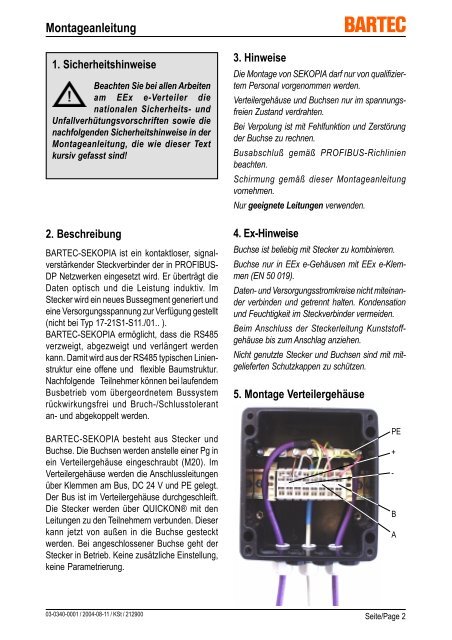
5. Montage Verteilergehäuse<br />
PE<br />
+<br />
-<br />
B<br />
A<br />
03-0340-0001 / 2004-08-11 / KSt / 212900<br />
Seite/Page 2
<strong>Montageanleitung</strong><br />
Anschluß Verteilergehäuse<br />
■ Ankommende Busleitung Klemmen A, B und<br />
Schirm anschliessen.<br />
■ Abgehende Busleitung ebenfalls auf Klemmen<br />
A, B und Schirm anschliessen.<br />
■ Versorgungsspannung DC 24 V auf Klemmen<br />
+ und - anschliessen.<br />
■ PE anschliessen.<br />
■ Aderleitungen A, B, + und - an die gekennzeichneten<br />
Klemmen anschliessen.<br />
■ PE auf Schirmschiene klemmen.<br />
■ Korrekten Anschluß prüfen.<br />
■ Schutzkappe erst vor Gebrauch entfernen.<br />
■ Konfigurierter Stecker kann von außen auf<br />
Buchse aufgesteckt werden. Zum Lösen am<br />
Entriegelungsring ziehen.<br />
Buchsenanschluß<br />
RD = B (Bus)<br />
6. Montage Steckeranschluß<br />
Gewinde M20<br />
BN = +<br />
GNYE = GND<br />
Schutzkappe SW 24<br />
GN = A (Bus)<br />
BU = -<br />
■ Aderleitungen<br />
A = grün (Bus), B = rot (Bus),<br />
+ = braun, - = blau,<br />
PE = grüngelb<br />
■ Korrekter Anschluß der Leitungen A, B, +, - und<br />
PE beachten.<br />
■ Gehäuse durch drehen lösen und vom Stecker<br />
abziehen.<br />
Hinweis: Dichtung und Spleißring auffangen !<br />
Stecker Spleißring Dichtung und Zugentlastung<br />
Buchseneinbau in Verteilergehäuse<br />
SW 17 Entriegelungsring Gehäuse<br />
■ Leitungen siehe Seite 8.<br />
■ Leitung um 20 mm abisolieren.<br />
Buchse<br />
Gewinde M20<br />
SW 24<br />
■ Schirm entfernen.<br />
Achtung: Litzen nicht abisolieren !<br />
■ Leitung durch Gehäuse, Dichtung und Zugentlastung<br />
schieben.<br />
■ Buchsen von außen in Verteilergehäuse einschrauben<br />
03-0340-0001 / 2001-12-10 / KSt / 212900<br />
■ Adern durch Spleißring stecken.<br />
Seite/Page 3
<strong>Montageanleitung</strong><br />
■ Entsprechende Adern in<br />
die gekennzeichnete<br />
Kerben (A, B, + und -)<br />
einlegen (bei Typ<br />
17-21S1-S11./01.. nur<br />
A und B verwenden).<br />
B<br />
A<br />
7. Schirmung<br />
■ Überstände der Adern<br />
abschneiden. -<br />
+<br />
■ Spleißring mit Adern in Federklemme einführen.<br />
Achtung: Kodierung beachten !<br />
■ Dichtung, Zugentlastung und Gehäuse nachschieben.<br />
■ Gehäuse auf Stecker aufschrauben und von<br />
Hand fest anziehen.<br />
SW 17<br />
■ Busleitungen zu Verteilergehäusen beidseitig<br />
erden.<br />
■ Schirm zum Abzweig am Teilnehmer erden.<br />
Hinweis: Komplette galvanische Trennung<br />
zu jedem Teilnehmer.<br />
8. Busabschluß<br />
■ Bis zum Anschlag mit einem Gabelschlüssel<br />
(SW 17) anziehen.<br />
■ Verbindung kontrollieren.<br />
■ Korrekt konfektionierter Stecker muß in<br />
Buchse einrasten.<br />
Verdrahtung vereinfacht dargestellt !<br />
Busabschluß<br />
Busende !<br />
Eine Buchse mit<br />
integriertem aktiven<br />
Busabschluß verwenden.<br />
■ Bus am Segmentanfang und Segmentende<br />
abschliessen.<br />
Hinweis: Stecker immer Segmentanfang<br />
Busabschluß ist integriert.<br />
■ Buchse auch mit Busabschluß erhältlich.<br />
Bus DP/V1 RS<br />
Bus DP/V1 RS<br />
DC 24 V<br />
03-0340-0001 / 2004-08-11 / KSt / 212900<br />
DP/V1<br />
RS485<br />
Seite/Page 4
<strong>Montageanleitung</strong><br />
9. Leitungen<br />
Hinweis:<br />
Für zuverlässige Abdichtung und Kontaktierung geeignete Leitungen verwenden !<br />
Die Leitung soll fest verlegt werden und darf höchstens zehn mal ausgewechselt werden.<br />
Allgemeine Leitungsanforderungen:<br />
■ Aderaufbau:<br />
2 verdrillte Aderpaare (RS485 und Versorgung)<br />
1 verdrilltes Aderpaar (nur RS485-Nutzung oder Typ 17-21S1-S11./01..)<br />
■ Aderquerschnitt: 0,34 - 0,5 mm² mehr- oder feindrähtig (Klasse 2-5)<br />
■ Aderisolation:<br />
PE oder PVC<br />
■ Aderaußendurchmesser: 1,3 - 1,7 mm<br />
■ Schirm:<br />
Kupfergeflecht (auch mit zusätzlicher Folie)<br />
■ Durchmesser ohne Mantel: max. 4,3 mm<br />
■ Mantelaußendurchmesser: 6,5 - 7,5 mm<br />
■ Mantelfarbe:<br />
blau (EEx i-Version)<br />
grau oder Violett (EEx e- und nicht Ex-Version)<br />
schwarz (für Außen- und Erdverlegung)<br />
■ Normen: DIN EN 60079-14<br />
(VDE 0165 Teil 1)<br />
Kapitel 9 und 12.2.2<br />
Geprüfte Leitungen für Stecker<br />
Bezeichnung Farbe Bestell-Nr.<br />
BARTEC Schlauchleitung Li2YCY (TP) 2 x 2 x 0,34 mm² blau (EEx i) 02-4042-0014<br />
BARTEC Schlauchleitung BUS L2/FIP 1 x 2 x 22 AWG blau (EEx i) 02-4022-0005<br />
Lapp-Kabel Unitronic-Li2YCY (TP) 2 x 2 x 0,34 mm² grau (EEx e) 0031 325 R<br />
Siemens PROFIBUS flexibel 1 x 2 x 22 AWG violett 6XV1 830-0PH10<br />
Außen- und Erdverlegung<br />
Lapp-Kabel Unitronic-Li2YCYv (TP) 1 x 2 x 0,34 mm² schwarz 0031 365 R<br />
Empfohlene Leitungen für Verteilergehäuse<br />
Bezeichnung Farbe Bestell-Nr.<br />
Siemens Standard 1 x 2 x 0,34 mm² violett 6XV1 830-0AH10<br />
Siemens halogenfrei/UV-beständig 1 x 2 x 0,34 mm² schwarz 6XV1 830-0BH10<br />
Lapp-Kabel Unitronic-BUS L2/FIP 1 x 2 x 0,34 mm² violett 2170 220 T<br />
mit zusätzlichen Versorgungsadern<br />
Lapp-Kabel Unitronic-BUS COMBI L2/FIP 1 x 2 x 0,34 mm²<br />
3 x 1 mm² violett 2170 225 T<br />
03-0340-0001 / 2001-12-10 / KSt / 212900 Seite/Page 5
<strong>Montageanleitung</strong><br />
10. Möglichkeiten mit SEKOPIA<br />
11. Instandhaltung<br />
Halten Sie die für die Instandhaltung, Wartung und<br />
Prüfung von zugehörigen Betriebsmitteln geltenden<br />
Bestimmungen gemäß Richtlinie 1999/92/EG,<br />
IEC 60079-19 sowie EN 60079-17 ein !<br />
Beachten Sie die nationalen Abfallbeseitigungsvorschriften<br />
bei der Entsorgung.<br />
Instandsetzung<br />
Reparaturen an explosionsgeschützen<br />
Betriebsmitteln dürfen nur von dazu<br />
befugten Personen mit Original-<br />
Ersatzteilen und nach dem Stand der<br />
Technik ausgeführt werden. Die dafür geltenden<br />
Bestimmungen sind zu beachten.<br />
Wartung<br />
Bei sachgerechtem Betrieb, unter Beachtung der<br />
Montagehinweise und Umgebungsbedingungen,<br />
ist keine ständige Wartung erforderlich.<br />
Inspektion<br />
Gemäß IEC 60079-19 und EN 60079-17 ist der<br />
Betreiber elektrischer Anlagen in explosionsgefährdeten<br />
Bereichen verpflichtet, diese durch<br />
eine Elektrofachkraft auf ihren ordnungsgemäßen<br />
Zustand prüfen zu lassen.<br />
03-0340-0001 / 2004-08-11 / KSt / 212900<br />
Seite/Page 6
Mounting instructions<br />
1. Safety instructions<br />
While untertaking and servicing<br />
at the quick-change socket, the<br />
national safety rules and<br />
regulations for prevention of accidents<br />
have to be observed as well as the safety<br />
instructions included within these<br />
operating instructions and set in italics the<br />
same as this text!<br />
2. Description<br />
BARTEC-SEKOPIA is a contact-free, signal<br />
amplifying plug connector which is plugged into<br />
PROFIBUS-DP networks. It transfers the data<br />
optically and the power inductively. A new bus<br />
segment is generated inside the plug and a supply<br />
voltage is made available (not with type 17-21S1-<br />
S11./01..).<br />
BARTEC-SEKOPIA enables the RS485 to be<br />
branched, forked and extended. In this way the<br />
RS485's typically linear structure is turned into an<br />
open and flexible tree structure. Participants<br />
downstream can be coupled to and uncoupled<br />
from the overriding bus system feedback-free and<br />
tolerant to open/short-circuit during bus operation.<br />
BARTEC-SEKOPIA consists of plugs and sockets.<br />
The sockets are screwed into a distribution box<br />
(M20) instead of a cable gland. In the distribution<br />
box the connection leads are connected via<br />
terminals to the bus, DC 24 V and PE. The bus is<br />
looped through the distribution box. The plugs are<br />
connected to the participants using the leads via<br />
QUICKON ® . This can be plugged into the socket<br />
from outside. When the socket is connected, the<br />
plug goes into operation. No additional setting, no<br />
parameterising.<br />
3. Note<br />
SEKOPIA may only installed by qualified staff.<br />
Wire the distribution box and the sockets only when<br />
system is deenergized.<br />
If the wrong poles are connected, faulty functioning<br />
and destruction of the socket have to be expected.<br />
Observe the bus termination according to the<br />
PROFIBUS guidelines.<br />
Screening as described in these installation<br />
instructions.<br />
Only use suitable cables.<br />
4. Ex note<br />
Combine the socket with any of the plugs.<br />
Socket only in EEx e housings with EEx e terminals<br />
(EN 50 014).<br />
Data and supply current circles not interconnect<br />
and keep separate. Avoid condensation and<br />
humidity in the plug connector.<br />
When connecting the plug cable screw the plastic<br />
housing to its limit.<br />
Unused plugs and sockets are to be protected<br />
using the protective caps supplied.<br />
5. Mounting distribution box<br />
PE<br />
+<br />
-<br />
B<br />
A<br />
03-0340-0001 / 2001-12-10 / KSt / 212900<br />
Seite/Page 7
Mounting instructions<br />
Connecting distribution box<br />
■ Connect incoming bus lines to terminals A, B<br />
and screen.<br />
■ Connect outgoing bus lines also to terminals<br />
A,B and screen.<br />
■ Connect the DC 24 V supply voltage to the<br />
terminals + and -.<br />
■ Connect PE.<br />
■ Connect leads A, B, + and - to labelled terminals.<br />
■ Connect PE to the screen rail.<br />
■ Check that the installation is correct.<br />
■ Remove protective cover only before the device<br />
is used.<br />
■ A configured plug can be inserted from the<br />
outside into the socket. For removing it pull the<br />
release ring.<br />
Socket connection<br />
RD = B (Bus)<br />
6. Installation plug connection<br />
Thread M20<br />
BN = +<br />
GNYE = GND<br />
Protective<br />
cover<br />
Size 24<br />
GN = A (Bus)<br />
BU = -<br />
■ Cable leads<br />
A = green (bus), B = red (bus),<br />
+ = brown, - = blue,<br />
PE = green and yellow<br />
■ Ensure the correct connection of the lines<br />
A, B, +, - and PE.<br />
■ Detach the casing by twisting and pull it off the<br />
plug.<br />
Note: Make sure you catch the seal and the<br />
split ring !<br />
Plug Split ring Seal and strain<br />
relief<br />
Installation of socket into the distribution box<br />
Size 17 Release ring Casing<br />
■ Cable see page 8.<br />
■ Remove 20 mm of the isolation from the cable.<br />
Socket<br />
Thread M20<br />
Size 24<br />
■ Remove the screen.<br />
Warning: Do not remove insulation from leads!<br />
■ Push the cable through the casing, the seal and<br />
the strain relief.<br />
■ Screw sockets from outside into the distribution<br />
box.<br />
03-0340-0001 / 2004-08-11 / KSt / 212900<br />
■ Stick leads through the split ring.<br />
Seite/Page 8
Mounting instructions<br />
■ Insert the appropriate<br />
B<br />
A<br />
leads (A, B, + and -) into<br />
the labelled grooves<br />
(with type 17-21S1-S11./<br />
01.. only use A and B).<br />
■ Cut off the projecting<br />
part of the leads. - +<br />
■ Insert the split ring with leads into the spring<br />
terminal.<br />
Warning: Observe coding !<br />
■ Next insert seal, strain relief and casing.<br />
7. Screen<br />
■ Screw the casing onto the plug and tighten<br />
manually.<br />
SW 17<br />
■ The bus connections to the distribution box must<br />
be earthed on both sides.<br />
■ Earth the screen where it branches off to the<br />
participant.<br />
Note: Each participant is be completely<br />
galvanically separated.<br />
8. Bus termination<br />
■ Tighten using a spanner (size 17) until the stop<br />
is reached.<br />
■ Check the connection.<br />
■ A correctly installed plug must lock into the<br />
socket.<br />
Bus termination End of bus !<br />
Use a socket with integrated<br />
active bus termination.<br />
The illustration of the wiring is simplified !<br />
■ Connect the bus at the start and the end of the<br />
segment.<br />
Note: The plug is always segment start.<br />
The bus termination is always<br />
integrated.<br />
■ Sockets are also available with endtermination.<br />
Bus DP/V1 RS<br />
Bus DP/V1 RS<br />
DC 24 V<br />
03-0340-0001 / 2001-12-10 / KSt / 212900<br />
DP/V1<br />
RS485<br />
Seite/Page 9
Mounting instructions<br />
9. Cables<br />
Note:<br />
For retiable seals and contacts use suitable cables !<br />
General requirements for the cables:<br />
■ Lead structure: 2 twisted pairs of leads (RS485and power supply )<br />
1 twisted pair of leads (only for use by RS485)<br />
■ Lead cross-section: 0.34 - 0.5 mm² strandes or fine stranded wires (class 2-5)<br />
■ Lead insulation: PE or PVC<br />
■ External lead diameter: 1.3 - 1.7 mm<br />
■ Screen:<br />
copper braid (also with additional foil)<br />
■ Diameter without jacket: max. 4.3 mm<br />
■ Jacket diameter: 6.5 - 7.5 mm<br />
■ Jacket colour: blue (EEx i version)<br />
gray or violet (EEx e and non-Ex version)<br />
black (for exterior use and underground installation)<br />
■ Standards: DIN EN 60079-14<br />
(VDE 0165 part 1)<br />
chapter 9 and 12.2.2<br />
Approved cables for plug<br />
Name Colour Order no.<br />
BARTEC Sheathed cable Li2YCY (TP) 2 x 2 x 0,34 mm² blue (EEx i) 02-4042-0014<br />
BARTEC Sheathed cable BUS L2/FIP 1 x 2 x 0,34 mm² blue (EEx i) 02-4022-0005<br />
Lapp-Kabel Unitronic-Li2YCY (TP) 2 x 2 x 0,34 mm² grey (EEx e) 0031 325 R<br />
Siemens PROFIBUS flexibly 1 x 2 x 22 AWG violet 6XV1 830-0PH10<br />
Exterior use and underground installation<br />
Lapp-Kabel Unitronic-Li2YCYv (TP) 1 x 2 x 0,5 mm² black 0031 365 R<br />
Recommended cables for distribution box<br />
Name Colour Order no.<br />
Siemens Standard 1 x 2 x 0,34 mm² violet 6XV1 830-0AH10<br />
Siemens halogenfrei/UV-beständig 1 x 2 x 0,34 mm² black 6XV1 830-0BH10<br />
Lapp-Kabel Unitronic-BUS L2/FIP 1 x 2 x 0,34 mm² violet 2170 220 T<br />
with additional power supply leads<br />
Lapp-Kabel Unitronic-BUS COMBI L2/FIP 1 x 2 x 0,34 mm²<br />
3 x 1 mm² violet 2170 225 T<br />
03-0340-0001 / 2004-08-11 / KSt / 212900<br />
Seite/Page 10
Mounting instructions<br />
10. Possibilities with SEKOPIA<br />
11. Maintenance<br />
The national regulations applicable to the<br />
maintenance, servicing and test of apparatus for<br />
explosive atmospheres and the general rules of<br />
engineering 1999/92/EC, IEC 60079-19 and<br />
EN 60079-17 must be observed.<br />
Follow national regulations for disposal.<br />
Repairs<br />
Repairs at explosion proof equipment<br />
must only be carried out by authorized<br />
persons with original manufactures<br />
components.<br />
Servicing<br />
No regular maintenance is required as long as the<br />
maximum operation conditions are observed.<br />
Inspection<br />
Observe the relevant national regulations! For<br />
example in Germany the user of an electrical<br />
installation in explosive atmospheres is obliged to<br />
have it inspected by a skilled electrical engineer<br />
with regard to its proper condition in accordance<br />
with IEC 60079-19 and EN 60079-17.<br />
03-0340-0001 / 2001-12-10 / KSt / 212900<br />
Seite/Page 11