Das Zubehör So wichtig wie der Ventilator selbst The Accessories ...
Das Zubehör So wichtig wie der Ventilator selbst The Accessories ...
Das Zubehör So wichtig wie der Ventilator selbst The Accessories ...

Sie wollen auch ein ePaper? Erhöhen Sie die Reichweite Ihrer Titel.
YUMPU macht aus Druck-PDFs automatisch weboptimierte ePaper, die Google liebt.
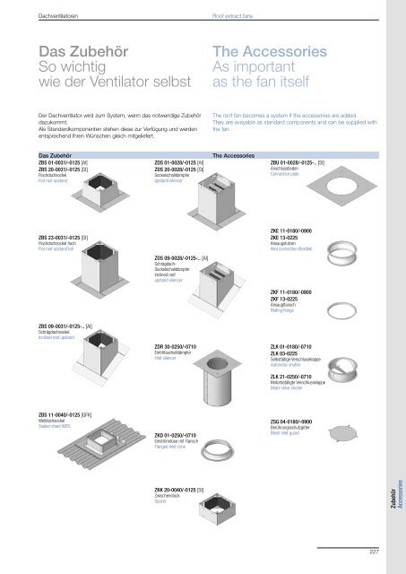
Dachventilatoren Roof extract fans<br />
<strong>Das</strong> <strong>Zubehör</strong><br />
<strong>So</strong> <strong>wichtig</strong><br />
<strong>wie</strong> <strong>der</strong> <strong>Ventilator</strong> <strong>selbst</strong><br />
Der Dachventilator wird zum System, wenn das notwendige <strong>Zubehör</strong><br />
dazukommt.<br />
Als Standardkomponenten stehen diese zur Verfügung und werden<br />
entsprechend Ihren Wünschen gleich mitgeliefert.<br />
<strong>Das</strong> <strong>Zubehör</strong> <strong>The</strong> <strong>Accessories</strong><br />
ZBS 01-0031/-0125 [Al]<br />
ZBS 20-0031/-0125 [St]<br />
Flachdachsockel<br />
Flat roof upstand<br />
ZBS 23-0031/-0125 [St]<br />
Flachdachsockel hoch<br />
Flat roof upstand tall<br />
ZBS 09-0031/-0125-.. [Al]<br />
Schrägdachsockel<br />
Inclined roof upstand<br />
ZBS 11-0040/-0125 [GFK]<br />
Welldachsockel<br />
<strong>So</strong>aker sheet WDS<br />
ZDS 01-0028/-0125 [Al]<br />
ZDS 20-0028/-0125 [St]<br />
<strong>So</strong>ckelschalldämpfer<br />
Upstand silencer<br />
ZDS 09-0028/-0125-.. [Al]<br />
Schrägdach-<br />
<strong>So</strong>ckelschalldämpfer<br />
Inclined roof<br />
upstand silencer<br />
ZDR 30-0250/-0710<br />
Eintrittsschalldämpfer<br />
Inlet silencer<br />
ZKD 01-0250/-0710<br />
Einströmdüse mit Flansch<br />
Flanged inlet cone<br />
ZKK 20-0040/-0125 [St]<br />
Zwischenstück<br />
Spacer<br />
<strong>The</strong> <strong>Accessories</strong><br />
As important<br />
as the fan itself<br />
<strong>The</strong> roof fan becomes a system if the accessories are added.<br />
<strong>The</strong>y are avayable as standard components and can be supplied with<br />
the fan.<br />
ZBU 01-0028/-0125-.. [St]<br />
Anschlussboden<br />
Connection plate<br />
ZKE 11-0180/-0900<br />
ZKE 13-0225<br />
Ansaugstutzen<br />
Inlet connection (flexible)<br />
ZKF 11-0180/-0900<br />
ZKF 13-0225<br />
Ansaugflansch<br />
Mating flange<br />
ZLK 01-0180/-0710<br />
ZLK 03-0225<br />
Selbsttätige Verschlussklappe<br />
Automatic shutter<br />
ZLK 21-0250/-0710<br />
Motorbetätigte Verschlussklappe<br />
Motor drive shutter<br />
ZSG 04-0180/-0900<br />
Berührungsschutzgitter<br />
Mesh inlet guard<br />
227<br />
<strong>Zubehör</strong><br />
<strong>Accessories</strong>
Gebhardt<strong>Ventilator</strong>en Dachventilatoren Roof extract fans<br />
228<br />
Anwendungsbeispiele Samples<br />
RGA<br />
ZBS<br />
RFM<br />
ZKE<br />
ZLK<br />
ZKF<br />
RKA 32<br />
ZDS<br />
ZBS ZKE<br />
ZKF
Gebhardt<strong>Ventilator</strong>en Dachventilatoren Roof extract fans<br />
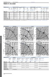
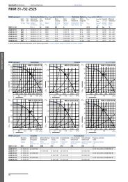
RDM 31/32<br />
ZBS<br />
Anwendungsbeispiele Samples<br />
RDA<br />
ZBS<br />
ZDR<br />
ZKD<br />
ZKE<br />
ZKF<br />
RKM 31<br />
ZBS 09<br />
TBA / RBA<br />
ZKE<br />
ZKF<br />
229
Gebhardt<strong>Ventilator</strong>en Dachventilatoren Roof extract fans<br />
<strong>Zubehör</strong> <strong>Accessories</strong><br />
ZBS 01 / 20<br />
ZBS 01-0031/-0125 [Al]<br />
ZBS 20-0031/-0125 [St]<br />
230<br />
Flachdachsockel Flat roof upstand<br />
Flachdachsockel aus Aluminium (ZBS 01) o<strong>der</strong> verzinktem<br />
Stahlblech (ZBS 20), mit schall- und wärmeisolieren<strong>der</strong><br />
Auskleidung.<br />
Ready-to-fit Flat roof upstand made of aluminium (ZBS<br />
01) or galvanised sheet steel (ZBS 20), with sound absorbing<br />
and thermal lining.<br />
ZBS 23<br />
Flachdachsockel hoch Flat roof upstand tall<br />
ZBS 23-0031/-0125 [St] Flachdachsockel hoch aus verzinktem Stahlblech (ZBS Flat roof upstand made of galvanised sheet steel (ZBS<br />
23), mit schall- und wärmeisolieren<strong>der</strong> Auskleidung. 23), with sound absorbing and thermal lining.<br />
ZBS 09<br />
Schrägdachsockel Inclined roof upstand<br />
ZBS 09-0031/-0125-** [Al] Schrägdachsockel aus Aluminium, mit schall- und wär- Upstand for inclined roof made of aluminium sheet,<br />
meisolieren<strong>der</strong> Auskleidung, lieferbar in 5 Grad-Abstu- provided with sound and thermal insulation, available in<br />
fung bis 45° Dachneigung.<br />
steps of 5 degrees from 5 to 45 degrees roof inclination.<br />
Bestellbeispiel: ZBS 09-0040-30 Schrägdachsockel für<br />
RDA 31-2528-4E und eine Dachneigung von 30°.<br />
Or<strong>der</strong> code (example): ZBS 09-0040-30 Upstand for<br />
inclined roof for RDA 31-2528-4E, roof inclination 30°.<br />
ZBS 11<br />
Welldachsockel <strong>So</strong>aker sheet WDS<br />
ZBS 11-0040/-0125 [GFK] Welldachsockel aus glasfaserverstärktem Polyester <strong>So</strong>aker sheets WDS, in glass fibre reinforced polyester,<br />
lösen das Montageproblem von Dachventilatoren auf solve the problem of fitting a roof unit to a corrugated<br />
Welldächern (Wellabstand 177 mm) bis 25° Dachnei- roof (“Pitch length” of corrugation 177 mm) with up to<br />
gung.<br />
25° pitch.<br />
ZKK 20<br />
Zwischenstück Spacer<br />
ZKK 20-0040/-0125 Zwischenstücke aus verzinktem Stahlblech (ZKK 20) An intermediate piece made of galvanised sheet steel<br />
gefertigt, sind bei Verwendung von Verschlussklappen (ZKK 20) has to be provided if a back draught damper<br />
in Verbindung mit <strong>So</strong>ckelschalldämpfern vorzusehen. is fitted together with a silencer upstand.<br />
Auf den <strong>So</strong>ckelschalldämpfer montiert sorgen sie für<br />
den notwendigen Abstand zwischen Schalldämpfer und<br />
Dachventilator, um die Verschlussklappe ohne Beeinträchtigung<br />
<strong>der</strong> Zuströmverhältnisse an den Dachventilator<br />
anzubringen.<br />
Fitted to the upstand itprovides the necessary distance<br />
between silencer and roof fan. This garantees an even<br />
air flow without creating extra pressure losses.<br />
ZBU 01<br />
Anschlussboden Connection plate<br />
ZBU 01-0028/-0125-.. [St] Anschlussboden aus verzinktem Stahlblech, mit Ge- Connection plate made of galvanised steel sheet with<br />
windestiften zur Befestigung einer Rohrleitung mit An- threaded bolts for fixing a flanged duct.<br />
schlussflansch.<br />
<strong>The</strong> connection plate has to be integrated into the roof<br />
Der Anschlussboden wird zusammen mit <strong>So</strong>ckelschall- with upstand silencer ZDS 01, ZDS 20 or upstand<br />
dämpfern ZDS 01, ZDS 20 o<strong>der</strong> Dachsockeln ZBS 01, ZBS 01, ZBS 20, ZBS 13, ZBS 23 in or<strong>der</strong> enable an<br />
ZBS 20, ZBS 23 in die Dachhaut eingebunden und<br />
ermöglicht den problemlosen Anschluss von Rohrleitungen.<br />
easy connection of ductwork.
Gebhardt<strong>Ventilator</strong>en Dachventilatoren Roof extract fans<br />
<strong>Zubehör</strong> <strong>Accessories</strong><br />
ZDH 20<br />
Haubenschalldämpfer Overhead silencer<br />
ZDH 20-0250/-0710 [St] Haubenschalldämpfer aus verzinktem Stahlblech mit Overhead silencer for sound reduction on discharge,<br />
vertikalem Luftaustritt zur austrittsseitigen Schalldämp- houses the fan and can be easily positioned, in place<br />
fung von Dachventilatoren.<br />
of the cowl. <strong>The</strong> silencer is made from galvanised steel<br />
Die Haubenschalldämpfer sind für die Baureihen sheet.<br />
RGA konzipiert und werden lose mit dem Venti- <strong>The</strong> overhead silencer is designed to fit to the RGA<br />
lator mitgeliefert. Die Montage <strong>der</strong> Haube erfolgt range. It is supplied with the fan as a kit to be as-<br />
bauseits vor Ort.<br />
sembled on site after installation of the fan base<br />
Der Haubenschalldämfer ZDH ist nicht für<br />
with motorimpeller.<br />
<strong>Ventilator</strong>en in ATEX zugelassen (Baureihe RGA 31- <strong>The</strong> Overhead Silencer ZDH is not available for<br />
....-.X-3G)!<br />
ATEX fans (Type RGA 31-....-.X-3G)!<br />
ZDH 20<br />
ZDS 01-0028/-0125 [Al]<br />
ZDS 20-0028/-0125 [St]<br />
ZDH 20<br />
ZDS 09-0028/-0125-** [Al]<br />
Dämpfungswerte Noise reduction values<br />
mittlerer Dämpfungswert Dämpfung in dB bei Mittenfrequenz in Hz<br />
average noise reduction Noise reduction in dB at centre frequencies in Hz<br />
ZDH 20- dB 63 125 250 500 1000 2000 4000 8000<br />
0250/-0355 11 0 -3 -5 -15 -22 -20 -13 -14<br />
0450/-0500 11 0 -5 -7 -15 -21 -20 -16 -17<br />
0560/-0710 11 -4 -8 -5 -13 -17 -18 -18 -17<br />
<strong>So</strong>ckelschalldämpfer Upstand silencer<br />
<strong>So</strong>ckelschalldämpfer für eintrittsseitige Schalldämpfung<br />
sind aus Aluminium (ZDS 01) bzw. aus verzinktem<br />
Stahlblech (ZDS 20) gefertigt.<br />
ZDS ..-0040 und ZDS ..-0056 mit herausnehmbaren<br />
Kulissen.<br />
Schrägdach-<strong>So</strong>ckelschalldämpfer Inclined roof upstand silencer<br />
Schrägdach-<strong>So</strong>ckelschalldämpfer für eintrittsseitige<br />
Schalldämpfung, aus Aluminium (ZDS 09), lieferbar in 5<br />
Grad-Abstufung bis 45° Neigungswinkel.<br />
Druckabnahme Pressure drop<br />
p A<br />
Pa<br />
150<br />
100<br />
50<br />
30<br />
20<br />
.<br />
V<br />
ZDS ..-0028<br />
Upstand silencer for the inlet side. <strong>The</strong> exterior skin is<br />
made of aluminium (ZDS 01) or galvanised sheet steel<br />
(ZDS 20).<br />
ZDS..–0040 and ZDS ..–0056 with removable absorber<br />
lining.<br />
Inclined roof upstand silencer for the inlet side. <strong>The</strong><br />
exterior skin is made of aluminium (ZDS 09), available in<br />
steps of 5 degrees from 5 to 45 degrees roof inclination.<br />
ZDS ..-0040<br />
ZDS ..-0056<br />
ZDS ..-0071<br />
ZDS ..-0090<br />
ZDS ..-0125<br />
500 1000 5000 10000 m³/h 40000<br />
0.1 0.5 1.0 m³/s 5.0 10<br />
Dämpfungswerte Noise reduction values<br />
mittlerer Dämpfungswert Dämpfung in dB bei Mittenfrequenz in Hz<br />
average noise reduction Noise reduction in dB at centre frequencies in Hz<br />
ZDS ..- dB 63 125 250 500 1000 2000 4000 8000<br />
0028 16 2 5 8 12 18 22 20 15<br />
0040 16 3 5 8 13 19 23 21 15<br />
0056 16 3 5 8 12 18 21 20 15<br />
0071 17 3 5 9 13 20 25 22 17<br />
0090 15 2 5 8 11 17 21 19 13<br />
0125 16 3 6 8 14 20 25 23 11<br />
231
Gebhardt<strong>Ventilator</strong>en Dachventilatoren Roof extract fans<br />
<strong>Zubehör</strong> <strong>Accessories</strong><br />
ZDR 30<br />
Eintrittsschalldämpfer Inlet silencer<br />
ZDR 30-0250/-0710 Der rohrartige Eintrittsschalldämpfer besitzt auf <strong>der</strong> dem <strong>The</strong> tubular inlet silencer has a square flange on the<br />
Dachventilator zugewandten Seite einen quadratischen side nearest to the roof unit, for bolting to the respective<br />
Flansch, passend zur Befestigung auf dem entspre- flat roof upstand. It slides inside the upstand, while the<br />
chenden Flachdachsockel. Er taucht in den Flach- opposite end can take either additional ducting or an<br />
dachsockel ein und an das untere Ende kann dann<br />
entwe<strong>der</strong> eine weiterführende Rohrleitung o<strong>der</strong> eine<br />
inlet cone.<br />
Einströmdüse montiert werden.<br />
<strong>The</strong> exterior skin is made of galvanised sheet steel, and<br />
the interior of galvanised perforated plate, the cavity<br />
between them is filled with non-flammable acoustic<br />
material.<br />
232<br />
Der Außenmantel besteht aus verzinktem Stahlblech<br />
und <strong>der</strong> Innenmantel aus verzinktem Lochblech. Der<br />
Zwischenraum ist mit nicht brennbarem, akustisch wirksamem<br />
Material gefüllt.<br />
Ein Innenkern ist bei Eintrittsschalldämpfern nicht<br />
vorhanden, so dass nur ein vernachlässigbar geringer<br />
Druckabnahme auftritt.<br />
Dämpfungswerte Noise reduction values<br />
mittlerer Dämpfungswert Dämpfung in dB bei Mittenfrequenz in Hz<br />
average noise reduction Noise reduction in dB at centre frequencies in Hz<br />
<strong>The</strong>re is no central core of material, so that any pressure<br />
loss will be insignificant.<br />
ZDR 30- dB 63 125 250 500 1000 2000 4000 8000<br />
0250 7 0 3 5 10 14 13 8 7<br />
0355 8 2 4 6 12 16 14 10 8<br />
0450 12 2 4 8.5 17 20 15 12 10<br />
0560 13 3 5 9 17 21 15 12 10<br />
0710 13 3 5 10 18 22 16 12 10<br />
ZKD 01<br />
Einströmdüse mit Flansch Flanged inlet cone<br />
ZKD 01-0250/-0710 Die Einströmdüse mit Flansch ist auf <strong>der</strong> Eintrittsseite <strong>The</strong> flanged inlet cone is for mounting un<strong>der</strong> the inlet<br />
des Eintrittsschalldämpfers zu montieren, wenn kein silencer, farthest from the unit, if no additional ducting<br />
weiteres Leitungssystem vorgesehen ist. Damit werden is planned.<br />
die Einströmbedingungen verbessert und Verluste re- This improves the intake flow environment and reduces<br />
duziert.<br />
losses.<br />
ZKE 11 / 13<br />
ZKE 11-0180/-0900<br />
ZKE 13-0225<br />
ZKF 11 / 13<br />
ZKF 11-0180/-0900<br />
ZKF 13-0225<br />
ZSG 04<br />
ZSG 04-0180/-0900<br />
Ansaugstutzen Inlet connection (flexible)<br />
Ansaugstutzen (elastische Stutzen) verhin<strong>der</strong>n die Weiterleitung<br />
von Körperschall zwischen Anlageteilen. Die<br />
Flanschmaße entsprechen <strong>der</strong> DIN 24 155 - 2.<br />
Ansaugflansch Mating flange<br />
Ansaugflansch für den Anschluss einer Rohrleitung auf<br />
<strong>der</strong> Raumseite des Dachventilators.<br />
Die Flanschmaße entsprechen <strong>der</strong> DIN 24 155 - 2.<br />
Inlet connection (flexible) prevents the transmission of<br />
vibration to other parts of the installation. Flange dimensions<br />
are in accordance with DIN 24 155 - 2.<br />
Mating flange, for joining an internal duct to the roof unit<br />
base.<br />
Flange dimensions are in accordance with<br />
DIN 24 155 - 2.<br />
Berührungsschutzgitter Mesh inlet guard<br />
Berührungsschutzgitter für die Eintrittsseite, nach<br />
DIN 24 167.<br />
Mesh inlet guard, in accordance with DIN 24 167.
Gebhardt<strong>Ventilator</strong>en Dachventilatoren Roof extract fans<br />
<strong>Zubehör</strong> <strong>Accessories</strong><br />
ZLK 01 / 03<br />
ZLK 01-0180/-0710<br />
ZLK 03-0225<br />
Selbsttätige Verschlussklappe Automatic shutter<br />
Selbsttätige Verschlussklappen ZLK 01 wirken bei Stillstand<br />
des Dachventilators als Rückschlagklappe und<br />
verhin<strong>der</strong>n ungewollten Kaltlufteinfall.<br />
Infolge von Wirbelbildung an den Klappenblechen erhöhen<br />
sich bei angebauter Verschlussklappe ZLK die<br />
eintritts- und austrittsseitigen Geräuschwerte um je ca.<br />
3 dB.<br />
p A<br />
Pa<br />
50<br />
20<br />
10<br />
5<br />
2<br />
ZLK ..-0355<br />
ZLK ..-0450<br />
ZLK ..-0560<br />
ZLK ..-0710<br />
ZLK ..-0250<br />
Automatic shutters ZLK 01 are working as back draught<br />
dampers at stand still of the roof fan thus avoiding uncontrolled<br />
intake of cold air.<br />
Due to turbulences generated by the back draught<br />
damper ZLK the sound data for intake and discharge<br />
may increase of app. 3 dB at discharge when a damper<br />
is fitted.<br />
ZLK 21<br />
Motorbetätigte Verschlussklappe Motor drive shutter<br />
ZLK 21-0250/-0710 Motorbetätigte Verschlussklappen ZLK 21 steuern den Motor actuated shutters ZLK 21 control the exhaust air<br />
(mechanisch o<strong>der</strong> natürlich erzeugten) Abluftstrom auch stream (mechanically or naturally generated) also if the<br />
bei außer Betrieb befindlichen Dachventilatoren o<strong>der</strong> fan is not in operation. This is true also for ventilation<br />
bei Dachlüftungshauben. Sie geben bei Einschalten hoods. <strong>The</strong> shutter opens when the fan is switched on<br />
des Klappenmotors die Abluftöffnung frei und schließen and closes at stop of the latter. When working in parallel<br />
nach dem Ausschalten automatisch. Im Parallelbetrieb with the fan the shutter is working like a non motorised<br />
mit dem Dachventilator wirken sie <strong>wie</strong> <strong>selbst</strong>tätige Verschlussklappen.<br />
one.<br />
Technische Daten Technical Data<br />
Nennspannung Nennfrequenz Kurzschlussstrom Leistungsaufnahme Schutzart<br />
Nominal voltage Nominal frequency Shortcut current Power consumption Protection class<br />
ZLK 21 V Hz A W IP<br />
230 50 0.08 85 43<br />
Druckabnahme Pressure drop<br />
Es wird empfohlen zwischen <strong>Ventilator</strong> und Verschlussklappe<br />
ein Kanalstück vorzusehen. Für diesen Fall<br />
gelten die angegebenen Druckverluste. Wenn die Verschlussklappe<br />
direkt am <strong>Ventilator</strong> angebracht wird,<br />
sind höhere Druckverluste zu erwarten.<br />
Die motorbetätigte Verschlussklappe ZLK 21 ist<br />
nicht für <strong>Ventilator</strong>en in ATEX zugelassen (Baureihe<br />
RGA 31-....-.X-3G)!<br />
1<br />
500 1000 5000 10000 m³/h<br />
V<br />
0.1 0.5 1.0 5.0 m³/s<br />
.<br />
200<br />
2000<br />
It is recommended to provide an intermediate duct piece<br />
between fan and shutter. For this case the indicated<br />
pressure drops are applicable. If the shutter is directly<br />
fitted after the roof fan, higher pressure drops have to<br />
be expected.<br />
<strong>The</strong> Motor drive shutter ZLK 21 is not available for<br />
ATEX fans (Type RGA 31-....-.X-3G)!<br />
233
Gebhardt<strong>Ventilator</strong>en Dachventilatoren Roof extract fans<br />
<strong>Zubehör</strong> <strong>Accessories</strong><br />
ZLK 21<br />
ZLK 21-0250/-0710<br />
234<br />
Motorbetätigte Verschlussklappe Motor drive shutter<br />
Ein kurzschlussfester Einphasen-Wechselstrom-Getriebemotor<br />
zieht die beiden Klappenbleche mit Hilfe von<br />
hochbeständigen Nylonschnüren auf und bleibt während<br />
<strong>der</strong> gesamten Öffnungszeit mit blockiertem Läufer<br />
eingeschaltet. Er besitzt keine Endschalter, die im Laufe<br />
<strong>der</strong> Zeit verschmutzen können.<br />
Nach dem Abschalten schließt eine Rückstellfe<strong>der</strong> automatisch<br />
die Klappenbleche.<br />
Der Klappenmotor ist am Schalter o<strong>der</strong> Schütz für den<br />
Dachventilator so anzuschliessen, dass er beim Einschalten<br />
des Dachventilators grundsätzlich mit in Betrieb<br />
genommen wird. Ein Hilfskontakt für die Schliessrichtung<br />
ist nicht erfor<strong>der</strong>lich.<br />
Beim Anbau einer motorbetätigten Verschlussklappe<br />
empfiehlt sich die Zwischenschaltung eines Kanalstückes<br />
zwischen Dachventilator und Klappe. Damit wird<br />
die Zugänglichkeit zur Klappe <strong>selbst</strong> und zum Klappenmotor<br />
erleichtert.<br />
Anschlussplan<br />
ZLK 21<br />
Connection diagram<br />
M<br />
3~<br />
A short circuit proof, single phase, actuator draws the<br />
shutter flaps by highly resistant nylon ropes to open position<br />
and stays switched on during the whole opening<br />
phase. <strong>The</strong> system is not equipped with end switches<br />
which could get dirty and ineffective during live time.<br />
After being switched off a push back spring closes the<br />
shutter.<br />
<strong>The</strong> actuator has to be electrically connected to the<br />
main fan relay enabling the shutter to be opened at every<br />
time when the fan is put into operation. An auxiliary<br />
contact for closing is not necessary.<br />
When providing an motorised shutter it is recommended<br />
to fit an intermediate duct piece between fan and<br />
shutter in or<strong>der</strong> to facilitate access to the shutter actuator.<br />
M<br />
1~<br />
L1<br />
L2<br />
L3<br />
N
Gebhardt<strong>Ventilator</strong>en Dachventilatoren Roof extract fans<br />
<strong>Zubehör</strong> <strong>Accessories</strong><br />
ILA<br />
SKS / EKS<br />
SKS<br />
EKS<br />
Motorantrieb für Austritts-Verschlussklappen Actuator for back draught dampers<br />
Der Antrieb für die Austritts-Verschlussklappen besteht<br />
aus einem Getriebemotor, welcher über Seilzüge mit<br />
den Klappen verbunden ist. Beim Anschalten des<br />
Motors öffnet dieser die Klappen bis zur maximal möglichen<br />
Öffnungs-Stellung und schließt nach dem Abschalten<br />
durch einen fe<strong>der</strong>betätigten Rücklauf.<br />
Die Ansteuerung des Getriebemotors kann abhängig<br />
o<strong>der</strong> unabhängig vom <strong>Ventilator</strong>motor erfolgen, so dass<br />
z. B. auch ohne <strong>Ventilator</strong>betrieb eine thermische Entlüftung<br />
unterstützt wird.<br />
Der Getriebemotor ist kurzschlussfest. Er steht bei<br />
geöffneten Klappen mit blockiertem Läufer unter Spannung.<br />
Bei Drehzahlsteuerung ist <strong>der</strong> Motor vor das Steuergerät<br />
zu schalten, damit die nominale Betriebsspannung<br />
zur Verfügung steht.<br />
Der Motorantrieb ILA ist nicht für <strong>Ventilator</strong>en in<br />
ATEX zugelassen (Baureihe RDM ..-....-.X-..)!<br />
M<br />
3~<br />
<strong>The</strong> discharge damper drive includes an actuator operating<br />
the flaps by a rope system. When switching the<br />
fan motor on the actuator is opening the damper to maximum<br />
aperture. At shut down the damper will brought<br />
to closure by a spring system.<br />
<strong>The</strong> control of the actuator can be realised in connection<br />
with the fan operation or independently of it, e.g. for<br />
enhancing static thermal ventilation.<br />
<strong>The</strong> actuator is designed “short circuit safe”. It is un<strong>der</strong><br />
current when open.<br />
If the fan motor is speed controlled by voltage variation<br />
the actuator has to be connected prior to the voltage<br />
controller in or<strong>der</strong> to supply always full voltage to the<br />
actuator.<br />
<strong>The</strong> Actuator ILA is not available for ATEX fans<br />
(Type RDM ..-....-.X-..)!<br />
Technische Daten Technical Data<br />
Nennspannung Nennfrequenz Kurzschlussstrom<br />
Nominal voltage Nominal frequency Shortcut current<br />
ILA V Hz A<br />
230 50 0.2<br />
Anschlussplan<br />
ILA<br />
Connection diagram<br />
M<br />
1~<br />
L1<br />
L2<br />
L3<br />
N<br />
PE<br />
<strong>So</strong>n<strong>der</strong>beschichtung Special coating<br />
Bei Einsatz unter normalen klimatischen Bedingungen<br />
und für Lüftungsanlagen ohne nennenswerte Korrosionsbeanspruchung<br />
ist die Standardausführung ohne<br />
zusätzlichen Korrosionsschutz völlig ausreichend.<br />
Bei erhöhter Anfor<strong>der</strong>ung kann jedoch optional ein<br />
erhöhter Korrosionsschutz <strong>der</strong> Klasse „S“ o<strong>der</strong> „K“ gewählt<br />
werden.<br />
behandlung mit einem Epoxy-Polyester-Mischpulver im<br />
Farbton RAL 7039 beschichtet, Schichtdicke 40 �m<br />
For the operation un<strong>der</strong> standard climatic conditions<br />
and for ventilation units without remarkable corrosion<br />
load the standard paint execution without particular<br />
corrosion protection will be sufficient.<br />
For increased corrosion loads the corrosion protection<br />
options class “S” or “K” can be selected.<br />
Erhöhter Korrosionsschutz Klasse S Increased corrosion protection class S<br />
<strong>The</strong> fan parts are thoroughly pretreated and coated with<br />
an Epoxy-Polyester-Pow<strong>der</strong>-Mix colour RAL 7039,<br />
Layer thickness 40 �m<br />
Erhöhter Korrosionsschutz Klasse K Increased corrosion protection class K<br />
Die <strong>Ventilator</strong>teile werden nach einer sorgfältigen Vorbehandlung<br />
mit einem Epoxy-Polyester-Mischpulver im<br />
Farbton RAL 7039 beschichtet, Schichtdicke 110 �m<br />
<strong>So</strong>n<strong>der</strong>farbtöne (nach RAL) auf Anfrage.<br />
Bei Dachventilatoren <strong>der</strong> Baureihe RGA kann die<br />
Kunststoffhaube nicht beschichtet werden.<br />
Bei ATEX-Dachventilatoren ist eine Beschichtung<br />
nicht möglich.<br />
<strong>The</strong> fan parts are thoroughly pretreated and coated with<br />
an Epoxy-Polyester-Pow<strong>der</strong>-Mix colour RAL 7039,<br />
Layer thickness 110 �m<br />
Special colours (of the RAL range) on request.<br />
<strong>The</strong> plastic cowl of the roof fan line RGA cannot be<br />
painted.<br />
Roof fans in ATEX-execution cannot be supplied<br />
with a coating.<br />
235
Gebhardt<strong>Ventilator</strong>en Dachventilatoren Roof extract fans<br />
<strong>Zubehör</strong> <strong>Accessories</strong><br />
ESH 21 ESH 21<br />
ESH 21<br />
ESH 21 � 5.5 kW<br />
236<br />
Revisionsschalter Isolator<br />
Ausführung<br />
Formschönes, schlagfestes Kunststoffgehäuse. Schutzart<br />
IP 44/65, in Aufbau-Ausführung, Schaltzeichen 0<br />
und I.<br />
Der Revisionsschalter enthält übersichtliche Anschlussklemmen<br />
und ist mit einem Anschlussbild versehen.<br />
Der ESH 21 bis 3 KW ist in IP 44 ausgeführt mit integrierter<br />
Sperrvorrichtung ausgerüstet.<br />
Der ESH 21 ab 5.5 KW ist in IP 65 ausgeführt. Er ist<br />
mit Deckelkupplung und integrierter Sperrvorrichtung<br />
ausgerüstet. Der Drehschalter ist in „0°- Stellung“ mit<br />
einem Bügelschloss abschließbar.<br />
Funktion<br />
Der Revisionsschalter trennt bei Reinigungs-, Wartungs-<br />
o<strong>der</strong> Reparaturarbeiten den <strong>Ventilator</strong> – vor Ort – sicher<br />
vom Netz und vermeidet so Unfälle durch unkontrolliertes<br />
Einschalten <strong>der</strong> Anlage durch Dritte. Es handelt sich<br />
nicht um einen Hauptschalter bzw. einen Schalter mit<br />
Not-Aus-Funktion<br />
Alle zugeordneten Revisionsschalter sind mit potentialfreien<br />
Kontakten ausgeführt (1 Schließer und<br />
1 Öffner).<br />
Die Revisionsschalter für Motoren mit eingebautem<br />
<strong>The</strong>rmokontakt haben grundsätzlich drei zusätzliche<br />
Hilfskontakte, damit bei Reinigungs- bzw. Wartungsarbeiten<br />
das vorgeschaltete Steuergerät nicht durch<br />
Motorstörung ausfällt.<br />
Vorsicht bei Kombination mit Frequenzumrichtern!<br />
Gegebenenfalls sind hierbei geson<strong>der</strong>te EMV-Maßnahmen<br />
erfor<strong>der</strong>lich; zudem Schalter niemals im stromführenden<br />
Zustand schalten, entstehende Überspannungen<br />
können den Schalter und die Wicklung gefährden!<br />
Design<br />
Beautifully shaped, shock-resistant plastic casing. Protection<br />
class IP 44/65, for surface mounting, switching<br />
symbols 0 and I.<br />
<strong>The</strong> isolator is fitted with connection terminals that are<br />
very accessible and has a connection diagram glued in<br />
the casing.<br />
<strong>The</strong> ESH 21 up to 3 KW is designed to IP 44. It is<br />
equipped with an integrated locking mechanism.<br />
<strong>The</strong> ESH 21 up to 5.5 KW is designed to IP 65. It<br />
is equipped with a coupling cover and an integrated<br />
locking mechanism. A padlock can in some cases be<br />
fitted to the rotary switch.<br />
Function<br />
<strong>The</strong> isolator disconnects the fan safely from the mains<br />
in the event of cleaning, maintenance or repair work on<br />
site and thus avoids accidents due to uncontrolled activation<br />
of the unit by third parties. It is no main switch or<br />
emergency switch.<br />
All of the classified isolators are fitted with potential-free<br />
contacts (1 closer and 1 opener).<br />
<strong>The</strong> isolators for motors with a built-in thermal contact<br />
have on principle three supplementary auxiliary contacts,<br />
so that the pre-switched control device does not<br />
drop out during cleaning or servicing work due to motor.<br />
Caution about combination with frequency inverter!<br />
Special EMC-action can be necessary, furthermore do<br />
not switch during operation, overvoltages can destroy<br />
the switch and the motor-winding.
Gebhardt<strong>Ventilator</strong>en Dachventilatoren Roof extract fans<br />
<strong>Zubehör</strong> <strong>Accessories</strong><br />
ESH 21 ESH 21<br />
ESH 21<br />
ESH 21 � 5.5 kW<br />
Revisionsschalter Isolator<br />
Technische Daten / Abmessungen Technical Data / Dimensions<br />
max. Motorleistung Abmessungen in mm, Än<strong>der</strong>ungen vorbehalten<br />
max. motor power Dimensions in mm, Subject to change<br />
ESH 21- kW a b c d<br />
0030-22 3.0 73 108 45 –<br />
0030-32 3.0 73 108 45 –<br />
0055-32 5.5 85 120 80 110<br />
0075-32 7.5 85 120 80 110<br />
0110-32 11.0 85 160 80 110<br />
0150-32 15.0 100 190 91 120<br />
0220-32 22.0 100 190 91 120<br />
0300-32 30.0 145 250 100 140<br />
0370-32 370 145 250 100 140<br />
0450-32 45.0 200 300 172 200<br />
0550-32 55.0 200 300 172 200<br />
0900-32 90.0 280 400 180 210<br />
0030-62 3.0 73 108 45 –<br />
0075-62 7.5 100 190 91 133<br />
0110-62 11.0 100 190 91 133<br />
0150-62 15.0 145 250 100 145<br />
0220-62 22.0 145 250 100 145<br />
0300-62 30.0 200 300 172 200<br />
0370-62 37.0 200 300 172 200<br />
0450-62 45.0 300 300 172 210<br />
0550-62 55.0 300 300 172 210<br />
0750-62 75.0 280 280 260 327<br />
0030-25 3.0 73 108 45 –<br />
0030-35 3.0 73 108 45 –<br />
0075-35 7.5 85 120 80 110<br />
0030-65 3.0 73 108 45 –<br />
0055-65 5.5 125 125 126 157<br />
0075-95 7.5 125 125 126 157<br />
Maßbild Measurement diagram<br />
ESH 21 � 3 kW<br />
a<br />
c<br />
ESH 21 � 5.5 kW<br />
a<br />
b<br />
Die Revisionsschalter sind nach Motornennleistungen<br />
eingeteilt. Aus <strong>der</strong> Typenbezeichung sind alle <strong>wichtig</strong>en<br />
Kenndaten ersichtlich.<br />
Bsp.: ESH 21-0030-65 = 3 KW-Schalter<br />
6 Hauptkontakte<br />
5 Hilfskontakte.<br />
0<br />
b<br />
d c<br />
<strong>The</strong> isolators are grouped according to motor rated<br />
power. All important characteristic data are evident from<br />
the model designation.<br />
E.g.: ESH 21-0030-65 = 3 KW-switch<br />
6 main contacts<br />
5 auxiliary contacts<br />
237
Gebhardt<strong>Ventilator</strong>en Dachventilatoren Roof extract fans<br />
<strong>Zubehör</strong> <strong>Accessories</strong><br />
EUM 33 EUM 33<br />
EUM 33<br />
238<br />
Motorschutz-Schaltgerät Motor protection unit<br />
für Drehstrommotoren (Normmotoren) ohne <strong>The</strong>rmokontakte<br />
Ausführung<br />
Kunststoffgehäuse in Schutzart IP 55, zulässige Umgebungstemperatur<br />
+40 °C, 40 – 60 Hz, Frontbedienung,<br />
für Wandaufbau.<br />
Motorschutz-Schaltgerät für eintourige, nicht drehzahlverän<strong>der</strong>bare<br />
Drehstrommotoren ohne <strong>The</strong>rmokontakte.<br />
Funktion<br />
Die Motorschutzschalter müssen bauseits auf den entsprechenden<br />
Auslösestrom eingestellt werden.<br />
Bei Überschreitung des eingestellten Auslösestromes<br />
trennt das Gerät durch einen thermischen Überlastauslöser<br />
den Motor vom Netz. Eine Wie<strong>der</strong>einschaltung ist<br />
durch Betätigung <strong>der</strong> „Ein-Taste“ vorzunehmen.<br />
Alle Motorschutz-Schaltgeräte EUM 33 sind auch für<br />
den Schutz von EExe-Motoren geeignet (PTB Prüfung<br />
Gesch.-Nr. 3.35/386.3060), sie müssen jedoch außerhalb<br />
von explosionsgefährdeten Bereichen montiert<br />
werden, da sie <strong>selbst</strong> nicht explosionsgeschützt ausgeführt<br />
sind.<br />
Die EUM 33-9000 Typen bestehen aus zwei einzelnen<br />
EUM 33 und dienen <strong>der</strong> Motorstromüberwachung bei<br />
zweitourigen <strong>Ventilator</strong>en (Motoren nach Dahlan<strong>der</strong>schaltung<br />
-GD / -HD und mit getrennter Wicklung -ID /<br />
-KD).<br />
Eine Schutzfunktion ist für die hohe Drehzahl nur<br />
bei vorhandener Dahlan<strong>der</strong>-Brücke gewährleistet.<br />
Eine Temperaturüberwachung ist mittels PTC (Kaltleiter)<br />
zu realisieren!<br />
for three-phase current motors (standard motors) without<br />
thermal contacts<br />
Design<br />
Plastic casing in protection class IP 55, permissible ambient<br />
temperature +40 °C, 40 – 60 Hz, frontal operation,<br />
for wall mounting.<br />
Motor protection unit for single-speed, non- variable<br />
speed three-phase current motors without thermal<br />
contacts.<br />
Function<br />
<strong>The</strong> motor protection units must be adjusted on site to<br />
the trigger current.<br />
If the preset trigger current is exceeded, the device disconnects<br />
the motor from the mains supply via a thermal<br />
overload release. Pressing the “on key” causes the unit<br />
to turn on again.<br />
All motor protection units EUM 33 are also suitable for<br />
the protection of EExe-motors (PTB-Prüfung Gesch-Nr.<br />
3.35/386.3060). <strong>The</strong>y must however be mounted outside<br />
of explosion endangered areas, since they are not<br />
themselves designed with explosion protection.<br />
<strong>The</strong> EUM-9000 types consist of two EUM 33 units.<br />
<strong>The</strong>y are provided for limiting the motor current of twospeed<br />
fans (Motors with Dahlan<strong>der</strong> connection -GD /<br />
-HD and motors with separated windings -ID / -KD).<br />
<strong>The</strong> safety function at high speed is only working if<br />
the Dahlan<strong>der</strong> bridge is in place. A temperature limitation<br />
can be realised with PTC thermistors.<br />
Technische Daten Technical Data<br />
Dauerstrom Einstellbereich max. Nennleistung AC-3<br />
Continuous flow Setting range max. rated power AC-3<br />
EUM A A kW<br />
33-0004-8D 0.4 0.24/-0.4 0.09<br />
33-0006-8D 0.6 0.4/- 0.6 0.12<br />
33-0010-8D 1.0 0.6/- 1.0 0.25<br />
33-0016-8D 1.6 1.0/- 1.6 0.55<br />
33-0024-8D 2.4 1.6/- 2.4 0.80<br />
33-0040-8D 4.0 2.4/- 4.0 1.50<br />
33-0060-8D 6.0 4.0/- 6.0 2.50<br />
33-0100-8D 10.0 6.0/-10.0 4.00<br />
33-0160-8D 16.0 10.0/-16.0 7.50<br />
33-0200-8D 20.0 16.0/-20.0 9.00<br />
33-0250-8D 25.0 20.0/-25.0 12.50<br />
33-0500-8D 50.0 40.0/-50.0 25.00<br />
33-0580-8D 58.0 50.0/-58.0 30.00
Gebhardt<strong>Ventilator</strong>en Dachventilatoren Roof extract fans<br />
<strong>Zubehör</strong> <strong>Accessories</strong><br />
EUM 33 EUM 33<br />
EUM 33<br />
Motorschutz-Schaltgerät Motor protection unit<br />
Typenübersicht für EUM 33-9000 Sätze Type overview for EUM 33-9000 units<br />
EUM EUM EUM<br />
33-9001-8D 33-0004-8D 33-0006-8D<br />
33-9002-8D 33-0004-8D 33-0010-8D<br />
33-9003-8D 33-0006-8D 33-0010-8D<br />
33-9004-8D 33-0006-8D 33-0016-8D<br />
33-9005-8D 33-0010-8D 33-0016-8D<br />
33-9006-8D 33-0010-8D 33-0024-8D<br />
33-9007-8D 33-0016-8D 33-0024-8D<br />
33-9008-8D 33-0016-8D 33-0040-8D<br />
33-9009-8D 33-0024-8D 33-0040-8D<br />
33-9010-8D 33-0024-8D 33-0060-8D<br />
33-9011-8D 33-0040-8D 33-0060-8D<br />
33-9012-8D 33-0040-8D 33-0100-8D<br />
33-9013-8D 33-0060-8D 33-0100-8D<br />
33-9014-8D 33-0060-8D 33-0160-8D<br />
33-9015-8D 33-0100-8D 33-0160-8D<br />
33-9016-8D 33-0100-8D 33-0200-8D<br />
33-9017-8D 33-0160-8D 33-0200-8D<br />
33-9018-8D 33-0160-8D 33-0250-8D<br />
33-9019-8D 33-0200-8D 33-0250-8D<br />
33-9020-8D 33-0250-8D 33-0580-8D<br />
33-9021-8D 33-0200-8D 33-0580-8D<br />
33-9022-8D 33-0100-8D 33-0250-8D<br />
Abmessungen in mm. Än<strong>der</strong>ungen vorbehalten Dimensions in mm, Subject to change<br />
EUM 33<br />
97<br />
160<br />
181<br />
47.5<br />
1 3 5<br />
2 4 6<br />
U1 V1 W1<br />
114<br />
130<br />
Anschlussplan Connection diagram<br />
EUM 33<br />
L1<br />
L2<br />
L3<br />
PE<br />
EUM33<br />
239
Gebhardt<strong>Ventilator</strong>en Dachventilatoren Roof extract fans<br />
<strong>Zubehör</strong> <strong>Accessories</strong><br />
ESM 01 / 02 / 03 / 04 ESM 01 / 02 / 03 / 04<br />
ESM 01 / 02 / 03 / 04<br />
240<br />
Motorvollschutz-Schaltgerät Motor protection unit<br />
für Motoren mit herausgeführten <strong>The</strong>rmokontakten<br />
Ausführung<br />
Formschönes, zweifarbiges Kunststoffgehäuse aus<br />
schlagfestem Polystyrol, Schutzart IP 54.<br />
Alle Geräte sind geeignet für Wandaufbau und beinhalten:<br />
Handschalter für Frontbedienung, Betriebsmeldeleuchte<br />
und von außen zugängliche Steuersicherung.<br />
Zulässige Umgebungstemperatur: +40 °C.<br />
Funktion<br />
Beim Überschreiten <strong>der</strong> zulässigen Wicklungstemperatur<br />
öffnet <strong>der</strong> in <strong>der</strong> Motorwicklung eingebettete<br />
<strong>The</strong>rmokontakt den Steuerstromkreis. Dadurch fällt das<br />
Hauptschütz ab und trennt den Motor vom Netz.<br />
Der Motor wird auch bei netzseitigem Ausfall <strong>der</strong> Steuerphase,<br />
so<strong>wie</strong> bei Kontaktfehlern und Leitungsbruch<br />
abgeschaltet.<br />
Die Motorvollschutz-Schaltgeräte verfügen über keine<br />
automatische Wie<strong>der</strong>einschaltung nach Netzspannungsausfall<br />
und sind somit eigensicher.<br />
Nach dem Abkühlen <strong>der</strong> Motorwicklung verhin<strong>der</strong>t eine<br />
Wie<strong>der</strong>einschaltsperre das <strong>selbst</strong>tätige Einschalten des<br />
Motors.<br />
Der Handschalter muss erst kurz in 0-Stellung und dann<br />
<strong>wie</strong><strong>der</strong> in Betriebsstellung geführt werden.<br />
Die Betriebsmeldeleuchte zeigt den Betrieb des Motors<br />
an. Sie erlischt im Störungsfall.<br />
Die Motorvollschutz-Schaltgeräte sind für Gruppenschaltung<br />
geeignet, d. h. mehrere Motoren gleicher<br />
Schaltung können an ein gemeinsames Schaltgerät<br />
angeschlossen werden.<br />
Die Summe <strong>der</strong> Motornennleistungen darf die maximale<br />
Gerätenennleistung nicht übersteigen, die <strong>The</strong>rmokontakte<br />
aller Motoren sind in Reihe zu schalten.<br />
Technische Daten Technical Data<br />
max. zulässige Motor-Nennleistung Nenn-Spannung Gewicht<br />
max. permitted rated motor power Nominal voltage Weight<br />
ESM kW V kg<br />
01-0020-5E 2.0 230 0.9<br />
01-0040-8D 4.0 400 0.9<br />
02-0040-8D 4.0 400 0.9<br />
03-0040-8D 4.0 400 0.9<br />
04-0040-8D 4.0 400 0.9<br />
Verschaltungsart siehe Anschlussplan | For connection type see diagrams<br />
Abmessungen in mm. Än<strong>der</strong>ungen vorbehalten Dimensions in mm, Subject to change<br />
ESM 01, 02, 03, 04<br />
Bitte immer die dem Gerät beiliegenden Schaltbil<strong>der</strong><br />
verwenden!<br />
140 30<br />
190 150<br />
for motors with fitted thermal contacts<br />
Design<br />
Beautifully shaped, two-tone plastic casing made of<br />
shock resistant polystyrol, protection class IP 54.<br />
All units are suitable for wall mounting and include: hand<br />
switches for frontal operation, operational signal lamp<br />
and control safety accessible from outside.<br />
Permissible ambient temperature: +40 °C.<br />
Function<br />
Should the motor winding temperature rise excessively,<br />
the imbedded motor winding thermal contact will open<br />
the control circuit, causing the mains relay to drop out<br />
and thus disconnect the motor from the mains supply.<br />
<strong>The</strong> motor will also be turned off in the case of a mainsside<br />
dropout of the control phase, as well as if the contacts<br />
fail or if the mains supply is interrupted.<br />
<strong>The</strong> motor protection units are not equipped with an<br />
automatic re-poweron after a mains voltage failure and<br />
are thus fail-safe.<br />
After the motor windings have cooled down, a lockout<br />
device in the relay circuit prevents the motor from<br />
switching itself on. <strong>The</strong> hand switch must first be momentarily<br />
turned to the 0-position and then back to the<br />
‘on’ position.<br />
<strong>The</strong> operational signal lamp indicates the operation of<br />
the motor. It goes out in the case of a malfunction.<br />
<strong>The</strong> motor protection units are suitable for group switching,<br />
i. e. several motors with the same switching can<br />
be connectedto a common switchingdevice.<br />
<strong>The</strong> sum of the motors’ rated power may not exceed<br />
the maximal device rated power. <strong>The</strong> thermal contacts<br />
of all motors are to be switched in series.<br />
Please use the enclosed wiring diagrams in the control<br />
boxes always!
Gebhardt<strong>Ventilator</strong>en Dachventilatoren Roof extract fans<br />
<strong>Zubehör</strong> <strong>Accessories</strong><br />
ESM 01 / 02 / 03 / 04 ESM 01 / 02 / 03 / 04<br />
ESM 01 / 02 / 03 / 04<br />
Motorvollschutz-Schaltgerät Motor protection unit<br />
Anschlussplan<br />
ESM 01-0020-5E<br />
Connection diagram<br />
Wechselstromausführung, 1 Drehzahl<br />
Alternating current model, single speed<br />
N<br />
PE N<br />
Netz<br />
Mains<br />
ACHTUNG: <strong>The</strong>rmokontakte (TK) immer in Reihe schalten!<br />
ATTENTION: for thermo contacts (TK) use always series connection!<br />
L1<br />
L1<br />
N L1 L2<br />
TK TK<br />
TK TK<br />
TK TK<br />
TK TK<br />
TK<br />
TK<br />
TK<br />
TK TK<br />
TK<br />
TK<br />
TK TK TK TK<br />
Anschlussmöglichkeit<br />
für 2 Motoren<br />
Connection type<br />
for 2 motors<br />
L3<br />
TK<br />
TK TK<br />
TK TK TK TK<br />
TK TK TK TK<br />
TK TK TK TK<br />
TK TK<br />
TK TK<br />
TK TK<br />
PE N L1 L2 L3<br />
Netz Anschlussmöglichkeit für 3 Motoren<br />
Mains Connection type for 3 motors<br />
N L1 L2<br />
Anschlussmöglichkeit für 3 Motoren<br />
Connection type for 3 motors<br />
ESM 01-0040-8D<br />
Drehstromausführung, 1 Drehzahl<br />
Three-phase current model, single speed<br />
L3<br />
U1 U1 U1 U2 U2 U2<br />
TK<br />
TK<br />
U1<br />
U1<br />
Z2<br />
TK Z1 U2<br />
Linkslauf<br />
Anti-clockwise<br />
rotation<br />
Z2<br />
TK Z1 U2<br />
Rechtslauf<br />
Clockwise<br />
rotation<br />
Motor 1-phase<br />
Motor 1-phase<br />
ACHTUNG: <strong>The</strong>rmokontakte (TK) immer in Reihe schalten!<br />
ATTENTION: for thermo contacts (TK) use always series connection!<br />
U1 U1 U1 V1 V1 V1 W1 W1 W1<br />
TK<br />
U1<br />
TK W2<br />
V1<br />
U2<br />
W1<br />
TK TK TK TK<br />
Y bzw. | or �<br />
Anschlussmöglichkeit für 2 Motoren<br />
Connection type for 2 motors<br />
TK TK<br />
TK TK<br />
TK TK<br />
TK<br />
TK<br />
TK<br />
TK<br />
TK TK TK TK<br />
TK TK<br />
V2<br />
1U 1V 1W 2U 2V 2W<br />
TK<br />
1U<br />
TK 2U<br />
PE N<br />
Netz<br />
L1 L2 L3<br />
TK TK<br />
Anschlussmöglichkeit für 3 Motoren<br />
Mains<br />
Connection type for 3 motors<br />
Motor 3-phase<br />
Motor 3-phase<br />
ESM 03-0040-8D<br />
Drehstromausführung, 2 Drehzahlen mit Dahlan<strong>der</strong>-Wicklung<br />
Three-phase current model, 2 speed with Dahlan<strong>der</strong> winding<br />
ACHTUNG: <strong>The</strong>rmokontakte (TK) immer in Reihe schalten!<br />
ATTENTION: for thermo contacts (TK) use always series connection!<br />
Anschlussmöglichkeit<br />
für 2 Motoren<br />
Connection type for 2 motors<br />
TK TK TK TK<br />
Motor 3-phase<br />
Motor 3-phase<br />
1V<br />
2V<br />
1W<br />
2W<br />
ESM 02-0040-8D<br />
Drehstromausführung, 2 Drehzahlen mit getrennten Wicklungen<br />
Three-phase current model, 2 speed with two separate windings<br />
ACHTUNG: <strong>The</strong>rmokontakte (TK) immer in Reihe schalten!<br />
ATTENTION: for thermo contacts (TK) use always series connection!<br />
N L1 L2<br />
L3<br />
TK TK<br />
TK TK<br />
TK TK<br />
TK<br />
TK<br />
TK<br />
TK<br />
TK TK TK TK<br />
TK TK<br />
1U 1V 1W 2U 2V 2W<br />
TK<br />
U1<br />
TK U2<br />
PE N<br />
Netz<br />
L1 L2 L3<br />
TK TK<br />
Anschlussmöglichkeit für 3 Motoren<br />
Mains<br />
Connection type for 3 motors<br />
ESM 04-0040-8D<br />
Drehstromausführung, 2 Drehzahlen Y/�-Umschaltung<br />
Three-phase current model, 2 speed with Y/�-connection<br />
N L1 L2<br />
L3<br />
Anschlussmöglichkeit<br />
für 2 Motoren<br />
Connection type for 2 motors<br />
TK TK TK TK<br />
Motor 3-phase<br />
Motor 3-phase<br />
ACHTUNG: <strong>The</strong>rmokontakte (TK) immer in Reihe schalten!<br />
ATTENTION: for thermo contacts (TK) use always series connection!<br />
TK TK<br />
TK TK<br />
TK TK<br />
TK<br />
TK<br />
TK<br />
TK<br />
TK TK TK TK<br />
TK TK<br />
V1<br />
V2<br />
W1<br />
W2<br />
U1 V1 W1 U2 V2 W2<br />
TK<br />
U1<br />
TK W2<br />
Anschlussmöglichkeit<br />
für 2 Motoren<br />
Connection type for 2 motors<br />
TK TK TK TK<br />
Motor 3-phase<br />
Motor 3-phase<br />
PE N<br />
Netz<br />
L1 L2 L3<br />
TK TK<br />
Anschlussmöglichkeit für 3 Motoren<br />
Mains<br />
Connection type for 3 motors<br />
V1<br />
U2<br />
W1<br />
V2<br />
241
Gebhardt<strong>Ventilator</strong>en Dachventilatoren Roof extract fans<br />
<strong>Zubehör</strong> <strong>Accessories</strong><br />
ETO 10 ETO 10<br />
ETO 10<br />
242<br />
Transformator mit 7 sekundären Anzapfungen Transformer with 7 secondary taps<br />
Ausführung<br />
Transformator nach DIN VDE 0550-1 mit aufgebauter<br />
Klemmenleiste für 7 Anzapfungen, ohne Gehäuse, geeignet<br />
für Schaltschrank-Einbau.<br />
Bei Drehstrom sind zwei Transformatoren erfor<strong>der</strong>lich,<br />
die in V-Schaltung anzuklemmen sind (siehe Schaltbild).<br />
Max. zulässige Umgebungstemperatur bei Nennstrombelastung<br />
+35 °C.<br />
ETO 10-....-5E<br />
Primärspannung: 230 V / 50-60 Hz<br />
Sekundärspannung: 230/180/160/140/120/100/80 V<br />
ETO 10-....-8D<br />
Primärspannung: 400 V / 50-60 Hz<br />
Sekundärspannung: 400/310/270/235/200/170/140 V<br />
Maßbild<br />
ETO 10<br />
Measurement diagram<br />
e<br />
a<br />
Anschlussplan Connection diagram<br />
ETO 10-....-5E<br />
Netz<br />
Motor<br />
ETO 10-....-8D<br />
Netz<br />
Motor<br />
Mains<br />
Motor<br />
Mains<br />
Motor<br />
L N U1 U2<br />
L1 L2 L3 U1 V1 W1<br />
230 V<br />
180 V<br />
160 V<br />
140 V<br />
120 V<br />
100 V<br />
80 V<br />
0 V<br />
Design<br />
Transformer according to DIN VDE 0550-1 with builton<br />
terminal strip for 7 taps, without casing, suitable for<br />
control cabinet installation.<br />
Two transformers are necessary for three-phase current,<br />
which are to beconnected in a V-switching configuration<br />
(see Wiring diagram). Permissible ambient temperature<br />
at nominal current loading max. +35 °C.<br />
ETO 10-....-5E<br />
Primary voltage: 230 V / 50-60 Hz<br />
Secondary voltage: 230/180/160/140/120/100/80 V<br />
ETO 10-....-8D<br />
Primary voltage: 400 V / 50-60 Hz<br />
Secondary voltage: 400/310/270/235/200/170/140 V<br />
Technische Daten / Abmessungen<br />
Wechselstromausführung | Alternating current model<br />
Technical Data / Dimensions<br />
Nennstrom Abmessungen in mm, Än<strong>der</strong>ungen vorbehalten<br />
Nominal current Dimensions in mm, Subject to change<br />
ETO A a b c e øf h kg<br />
10-0018-5E 1.8 78 60 92 56 4.8 44 1.5<br />
10-0040-5E 4.0 96 80 107 84 5.8 61 2.5<br />
10-0070-5E 7.0 120 95 126 90 5.8 73 4.5<br />
10-0130-5E 13.0 135 110 135 104 5.8 86 7.0<br />
10-0220-5E 22.0 135 150 135 104 5.8 126 12.5<br />
Drehstromausführung | Three-phase current model<br />
Nennstrom Abmessungen in mm, Än<strong>der</strong>ungen vorbehalten<br />
Nominal current Dimensions in mm, Subject to change<br />
ETO A a b c e øf h kg<br />
10-0010-8D 1.0 78 60 92 56 4.8 44 1.5<br />
10-0020-8D 2.0 96 80 107 84 5.8 61 2.5<br />
10-0040-8D 4.0 120 95 126 90 5.8 73 4.5<br />
10-0065-8D 6.5 135 110 135 104 5.8 86 7.0<br />
10-0150-8D 15.0 135 150 135 104 5.8 126 12.5<br />
h<br />
b<br />
c<br />
øf<br />
400 V<br />
310 V<br />
270 V<br />
235 V<br />
200 V<br />
170 V<br />
140 V<br />
0 V<br />
0 V<br />
140 V<br />
170 V<br />
200 V<br />
235 V<br />
270 V<br />
310 V<br />
400 V
Gebhardt<strong>Ventilator</strong>en Dachventilatoren Roof extract fans<br />
<strong>Zubehör</strong> <strong>Accessories</strong><br />
ETH 31 / 35 / 36 / 37 ETH 31 / 35 / 36 / 37<br />
ETH 31 / 35 / 36 / 37<br />
Drehzahlsteller transformatorisch, 5-stufig, mit Gehäuse Speed setting transformatic, 5-step, with casing<br />
Ausführung<br />
Voll-Kunststoffgehäuse in Schutzart IP 54, Typ:<br />
ETH 31, 35 und ETH 37-0010/-0020-8D.<br />
Lackiertes Metallgehäuse in Schutzart IP 23, Typ:<br />
ETH 36 und ETH 37-0040/-0070-8D.<br />
Alle Geräte sind geeignet für Wandaufbau und beinhalten:<br />
Drehzahlsteuerung über Handschalter mit 0-Stellung<br />
und 5 Schaltstufen, Betriebsmeldeleuchte, 230<br />
V-Ausgang für z. B. Magnetventil.<br />
Zulässige Umgebungstemperatur: -25 °C bis +40 °C.<br />
ETH 31<br />
Diese Geräte enthalten keinen Motorvollschutz. Schutzschalter<br />
für <strong>The</strong>rmokontaktanschluss sind in die Leitung<br />
zwischen Steuergerät und Motor zu legen.<br />
Bei Gebhardt-Außenläufermotoren sind die <strong>The</strong>rmokontakte<br />
bereits in die Motorwicklung eingebunden.<br />
ETH 35, ETH 36, ETH 37<br />
Diese Geräte besitzen eine Motorvollschutzeinrichtung<br />
für <strong>The</strong>rmokontakt- bzw. Kaltleiteranschluss mit zusätzlicher<br />
Störmeldeleuchte, potentialfreiem Wechsler und<br />
Raumthermostatanschluss (Fern-Ein-Aus).<br />
Funktion<br />
Bei Motoren mit eingebauten <strong>The</strong>rmokontakten öffnen<br />
diese bei Überschreiten <strong>der</strong> zulässigen Wicklungstemperatur<br />
den Steuerstromkreis (ETH 31, 35, 36). Bei<br />
Motoren mit PTC-Kaltleiter wird bei Übertemperatur das<br />
integrierte Kaltleiterauslösegerät (ETH 37) angesprochen.<br />
Dadurch fällt das Hauptschütz ab und trennt den<br />
Motor vom Netz.<br />
Nach dem Abkühlen <strong>der</strong> Motorwicklung (ca. 2 Min.)<br />
bzw. nach Beheben <strong>der</strong> Störursache den Hauptschalter<br />
kurz in 0-Stellung und <strong>wie</strong><strong>der</strong> in Betriebsstellung drehen.<br />
Design<br />
Completely plastic casing in protection class IP 54, Type:<br />
ETH 31, 35 and ETH 37-0010/-0020-8D.<br />
Painted metal casing in protection class IP 23, Type:<br />
ETH 36 and ETH 37-0040/-0070-8D.<br />
All units are suitable for wall mounting and include:<br />
speed control via hand switch with 0-position and 5<br />
switching steps, operating signal lamp, 230 V output for<br />
e. g. a solenoid valve.<br />
Permissible ambient temperature: -25 °C up to +40 °C.<br />
ETH 31<br />
<strong>The</strong>se units include no motor protection unit. Protection<br />
switches for thermal contact connections are to be laid<br />
in the conductor between the control device and the<br />
motor. In Gebhardt externallymounted rotor motors,<br />
the thermal contacts are already bound into the motor<br />
winding.<br />
ETH 35, ETH 36, ETH 37<br />
<strong>The</strong>se units possess a motor protection installation for<br />
thermal contact or PTC connection with a supplementary<br />
warning signal lamp, a potential-free exchanger and<br />
a room thermostat connection (remote on – off).<br />
Function<br />
For motors with built-in thermal contacts, these open<br />
the control current circuit when the permissible winding<br />
temperature is exceeded (ETH 31, 35, 36). Motors<br />
equipped with PTC thermistor give an electrical signal to<br />
the trigger unit (ETH 37) when the temperature exceeds<br />
the default value. <strong>The</strong> trigger controls the main relay<br />
thus cutting the motor feed. This causes the main fuse<br />
to fall out and disconnect the motor from the mains.<br />
After the motor winding has cooled down (ca. 2 Min.) or<br />
after remedying the cause of the malfunction, respectively,<br />
turn the main switch temporarily to the 0-position<br />
and then back to the operational position.<br />
243
Gebhardt<strong>Ventilator</strong>en Dachventilatoren Roof extract fans<br />
<strong>Zubehör</strong> <strong>Accessories</strong><br />
ETH 31 / 35 / 36 / 37 ETH 31 / 35 / 36 / 37<br />
ETH 31 / 35 / 36 / 37<br />
Primärspannung<br />
Primary voltage:<br />
230 V; 50-60 Hz<br />
Sekundärspannung<br />
Secondary voltage:<br />
60/105/130/160/230 V<br />
Primärspannung<br />
Primary voltage:<br />
400 V; 50-60 Hz<br />
Sekundärspannung<br />
Secondary voltage:<br />
90/140/180/230/400 V<br />
244<br />
Drehzahlsteller transformatorisch, 5-stufig, mit Gehäuse Speed setting transformatic, 5-step, with casing<br />
Technische Daten Technical Data<br />
Wechselstromausführung | Alternating current model<br />
ohne Motorvollschutzeirichtung mit Motorvollschutzeinrichtung<br />
without motor protection installation with motor protection installation<br />
Nennstrom Netzsicherung Nennstrom Netzsicherung<br />
Nominal current Mains safety Nominal current Mains safety<br />
ETH A ETH A<br />
31-0020-5E 2.0 2 AT 35-0040-5E 4.0 6 AT<br />
31-0040-5E 4.0 6 AT 35-0070-5E 7.0 8 AT<br />
36-0200-5E 20.0 20 AT<br />
Drehstromausführung | Three-phase current model<br />
Abmessungen in mm. Än<strong>der</strong>ungen vorbehalten Dimensions in mm, Subject to change<br />
Maßbild<br />
ETH 31, 35, 36, 37<br />
Measurement diagram<br />
a<br />
1 2 3 4 5<br />
0<br />
b<br />
mit Motorvollschutzeinrichtung<br />
with motor protection installation<br />
Nennstrom Netzsicherung<br />
Nominal current Mains safety<br />
ETH A<br />
35-0010-8D 1.0 1 AT<br />
35-0020-8D 2.0 2 AT<br />
36-0040-8D 4.0 4 AT<br />
36-0070-8D 7.0 8 AT<br />
36-0140-8D 14.0 16 AT<br />
mit Motorvollschutzeinrichtung für Motoren mit PTC-Kaltleiter<br />
with motor protection installation for motors with PTC<br />
Nennstrom Netzsicherung<br />
Nominal current Mains safety<br />
ETH A<br />
37-0010-8D 1.0 1 AT<br />
37-0020-8D 2.0 2 AT<br />
37-0040-8D 4.0 4 AT<br />
37-0070-8D 7.0 8 AT<br />
ETH a b c d e f g kg<br />
31-0020-5E 155 200 150 144 98 6.2 30 4.0<br />
31-0040-5E 155 200 150 144 98 6.2 30 4.0<br />
35-0040-5E 155 200 150 144 98 6.2 30 4.0<br />
35-0070-5E 200 254 170 194 140 6.2 30 8.0<br />
36-0200-5E 225 305 165 265 188 6.2 30 17.0<br />
35-0010-8D 155 200 150 144 98 6.2 30 6.0<br />
35-0020-8D 200 254 170 194 140 6.2 30 8.0<br />
36-0040-8D 225 305 165 265 188 6.2 30 14.0<br />
36-0070-8D 225 305 165 265 188 6.2 30 20.0<br />
36-0140-8D 302 385 223 350 265 6.2 30 35.0<br />
37-0010-8D 200 254 170 194 140 6.2 30 5.5<br />
37-0020-8D 200 254 170 194 140 6.2 30 8.0<br />
37-0040-8D 225 305 165 265 188 6.2 30 14.0<br />
37-0070-8D 225 305 165 265 188 6.2 30 20.0<br />
c g e<br />
f<br />
d
Gebhardt<strong>Ventilator</strong>en Dachventilatoren Roof extract fans<br />
<strong>Zubehör</strong> <strong>Accessories</strong><br />
ETH 31 / 35 / 36 / 37 ETH 31 / 35 / 36 / 37<br />
ETH 31 / 35 / 36 / 37<br />
TK = <strong>The</strong>rmokontakt des Motors<br />
PTC = Positiver-Temperatur-<br />
Coeffizient (Kaltleiter) des<br />
Motors<br />
RT = Raumthermostat o<strong>der</strong><br />
externer Schalter<br />
� = zusätzlicher Ausgang,<br />
z. B. für Magnetventil,<br />
Leuchte, usw.<br />
� = freie Kontakte für Meldung<br />
„Betrieb/Störung“<br />
TK = <strong>The</strong>rmal contact of the<br />
motor<br />
PTC = Positive-Temperature-Coefficient<br />
(PTC-<strong>The</strong>rmistor)<br />
of the motor<br />
RT = Room thermostat or<br />
external switch<br />
� = additional outlet e. g. for<br />
solenoid valve, lamp, etc.<br />
� = free contacts for the<br />
status signal “Operating/<br />
Malfunction”<br />
Drehzahlsteller transformatorisch, 5-stufig, mit Gehäuse Speed setting transformatic, 5-step, with casing<br />
Anschlussplan<br />
ETH 31<br />
Connection diagram<br />
N L1 L2 L3<br />
N L1 L2 L3<br />
N L1 PE U1 U2 PE L1 N<br />
PE N L1 PE U1 U2 PE L1 N<br />
Netz<br />
Motor �<br />
Mains<br />
Motor<br />
Anschlussplan<br />
ETH 35-/36-....-5E<br />
Connection diagram<br />
N L1 PE U1 U2 TK TK RT RT PE L1 N 11 12 14<br />
PE N L1 PE U1 U2 PE L1 N 11 12 14<br />
Netz<br />
Motor<br />
� �<br />
Mains<br />
Motor<br />
Anschlussplan<br />
ETH 35-/36-....-8D<br />
Connection diagram<br />
PE U1 V1 W1 TK TK RT RT PE L1 N 11 12 14<br />
PE N L1 L2 L3 PE U1 V1 W1<br />
PE L1 N<br />
Netz<br />
Motor<br />
�<br />
Mains<br />
Motor<br />
Anschlussplan<br />
ETH 37-....-8D<br />
Connection diagram<br />
11 12<br />
�<br />
PE U1 V1 W1PTC<br />
PTC RT RT PE L1 N 11 12 14<br />
PE N L1 L2 L3 PE U1 V1 W1<br />
PE L1 N<br />
Netz<br />
Motor<br />
�<br />
Mains<br />
Motor<br />
11 12<br />
�<br />
14<br />
14<br />
245
Gebhardt<strong>Ventilator</strong>en Dachventilatoren Roof extract fans<br />
<strong>Zubehör</strong> <strong>Accessories</strong><br />
EPH 03 EPH 03<br />
EPH 03<br />
246<br />
Drehzahlsteller elektronisch, stufenlos Transformer electronic, stepless<br />
Ausführung<br />
Schlagfestes Kunststoffgehäuse (cremeweiß) in Schutzart<br />
IP 44, mit frontseitigem Drehknopf.<br />
Übersichtliche Klemmleiste für Netz und Motoranschluss.<br />
Bei Verwendung als Einbauausführung in Normalschalterdose<br />
wird <strong>der</strong> Drehzahlsteller mit Frontplatte einfach<br />
vom Gehäuseunterteil abgenommen.<br />
Funktion<br />
Der Drehzahlsteller enthält einen Drehknopf zur <strong>So</strong>llwertän<strong>der</strong>ung<br />
mittels Phasenanschnitt-Steuerung, Halbleitersicherung<br />
und einen Rückmeldeausgang.<br />
Der Drehzahlsteller EPH verfügt über keine Motorvollschutzeinrichtung!<br />
Für einen <strong>The</strong>rmokontaktanschluss wird unser Motorvollschutz-Schaltgerät<br />
EUM 11-0100-5E (IP 54) bzw. EUM<br />
21-0100-5E (IP 00, für Schaltschrankeinbau) empfohlen.<br />
~66<br />
�64<br />
�81<br />
L N<br />
Design<br />
Shock-resistant plastic casing (creamwhite) in protection<br />
class IP 44, with turn knob on the front side.<br />
Clearly arranged terminal strip for mains and motor<br />
connection.<br />
For use as an integral version in a standard switch box,<br />
the speedregulator with its front plate is simply removed<br />
from the casing un<strong>der</strong>side.<br />
Function<br />
<strong>The</strong> transformer contains a turn knob for the variation<br />
of the nominal value by means of phase-angle control,<br />
semiconductor fuse and a response output.<br />
<strong>The</strong> transformer EPH is not equipped with any motor<br />
protection installation!<br />
If thermo contacts are in use it is recommended to assure<br />
the electrical safety by installing motor protection<br />
units EUM 11-0100-5E (IP 54) or EUM 21-0100-5E (IP<br />
00, for integration in a panel).<br />
Technische Daten Technical Data<br />
Nennstrom Nenn-Spannung Frequenz Schmelzeinsatz<br />
Nominal current Nominal voltage Frequency Fuse<br />
EPH A V Hz<br />
03-0010-5E 1.0 230/240 50/60 F 1.0 A<br />
03-0020-5E 2.0 230/240 50/60 F 2.0 A<br />
03-0040-5E 4.0 230/240 50/60 F 4.0 A<br />
Abmessungen in mm. Än<strong>der</strong>ungen vorbehalten Dimensions in mm, Subject to change<br />
EPH 03-0010/-0040-5E EPH 03-0010/-0020-5E<br />
Aufbauausführung Einbauausführung<br />
Surface mounting version flush mounting version<br />
ø4<br />
Dichtung | Sealing<br />
Anschlussplan<br />
EPH 03<br />
Connection diagram<br />
N N<br />
Re M
Gebhardt<strong>Ventilator</strong>en Dachventilatoren Roof extract fans<br />
<strong>Zubehör</strong> <strong>Accessories</strong><br />
EPA 03 EPA 03<br />
EPA 03<br />
Drehzahlsteller elektronisch, stufenlos Transformer electronic, stepless<br />
Elektronischer Drehzahlsteller mit stufenlos einstellbarer<br />
Ausgangsspannung für <strong>Ventilator</strong>en mit regelbaren<br />
Wechselstrommotoren.<br />
Ausführung<br />
EPA 03-….-5E<br />
Voll-Kunststoffgehäuse in Schutzart IP 54<br />
Funktion<br />
Der Drehzahlsteller EPA 03 verfügt über eine Motorvollschutzeinrichtung<br />
für <strong>The</strong>rmokontaktanschluss, <strong>So</strong>llwerteingang,<br />
Hauptschalter, Betriebsmeldeleuchte, Halbleitersicherungen<br />
und Einstellmöglichkeiten für minimale<br />
und maximale Drehzahl.<br />
PE PE PE<br />
PE<br />
L1<br />
L1 N<br />
L1 N<br />
Netz 1~ 230V<br />
50/60Hz<br />
Mains 1~230V<br />
50/60Hz<br />
N U1 U1<br />
TK<br />
TK<br />
TK<br />
TK<br />
5<br />
U1 Z2<br />
Z1 U2<br />
U1 Z2<br />
Z1 U2<br />
U2 U2<br />
241<br />
213<br />
198<br />
12 11 14<br />
Electronic transformer with stepless adjustable output<br />
voltage for fans with controllable alternating current<br />
motors.<br />
Design<br />
EPA 03-….-5E<br />
Completely plastic casing in protection class IP 54.<br />
Function<br />
<strong>The</strong> Transformer EPA 03 is equipped with a motor<br />
protection installation for thermal contact connection,<br />
nominal value input, main switch, operating signal lamp,<br />
semiconductor fuses and adjustment options for minimal<br />
and maximal speed.<br />
Technische Daten Technical Data<br />
Schutzart max. Stromaufnahme Nenn-Spannung Frequenz ca. Gewicht<br />
Protection class max. current cons. Nominal voltage Frequency app. Weight<br />
EPA IP A V Hz kg<br />
03-0060-5E 54 0.2/- 6.0 230 50/60 1.3<br />
03-0100-5E 54 0.2/-10.0 230 50/60 1.9<br />
Abmessungen in mm. Än<strong>der</strong>ungen vorbehalten Dimensions in mm, Subject to change<br />
EPA 03<br />
10<br />
30<br />
137<br />
185<br />
Anschlussplan Connection diagram<br />
EPA 03<br />
Regler Direkt<br />
Direct controller<br />
Max. Kontaktbelastung 5 A / 250 V AC<br />
Max. contact capacity 5 A / 250 V AC<br />
C in Motor<br />
C in motor<br />
C in Motor<br />
C in motor<br />
TK<br />
TK<br />
24V<br />
GND<br />
1~ Motor<br />
mit eingebauten <strong>The</strong>rmokontakten<br />
1-phase motor<br />
with integrated thermo contacts<br />
1~ Motor<br />
mit eingebauten <strong>The</strong>rmokontakten<br />
1-phase motor<br />
with integrated thermo contacts<br />
122<br />
60<br />
10V<br />
GND<br />
Eingang (Ri > 100k�)<br />
Input (Ri > 100k�)<br />
E<br />
GND<br />
1k�<br />
Potentiometer<br />
+<br />
Eingang 0-10V<br />
Input 0-10V<br />
A<br />
GND<br />
+<br />
J3<br />
A<br />
B<br />
Ausgang<br />
0...10V<br />
(Imax=10mA)<br />
Output<br />
0...10V<br />
(Imax=10mA)<br />
247
Gebhardt<strong>Ventilator</strong>en Dachventilatoren Roof extract fans<br />
<strong>Zubehör</strong> <strong>Accessories</strong><br />
EPA 93 EPA 93<br />
EPA 93 Drehzahlsteller elektronisch, stufenlos Transformer electronic, stepless<br />
248<br />
für spannungsabhängig steuerbare Einphasenmotoren<br />
mit Kondensatorhilfswicklung<br />
Ausführung<br />
Mikroprozessorgesteuerter Drehzahlsteller mit sinusgeführter<br />
IGBT-Pulspausenmodulation, ohne Gleichspannungszwischenkreis;<br />
beson<strong>der</strong>s verlustarme<br />
Drehzahlstellung für spannungsabhängig steuerbare<br />
<strong>Ventilator</strong>antriebe mit Einphasen-Wechselstrommotoren<br />
durch Schaltbetrieb mit hoher Taktfrequenz (19 kHz),<br />
Wegfall von störenden Motorgeräuschen; funktionell<br />
integrierte Leistungsfaktor-Korrektur für sinusförmige<br />
Netzstromaufnahme; eingebautes Funkentstörfilter zur<br />
Einhaltung <strong>der</strong> EMV-Vorschriften.<br />
Funktion<br />
Drehzahlsteuerung: Gleichspannung 0-10 V (wahlweise<br />
mit externem Potentiometer o<strong>der</strong> externer Gleichspannung)<br />
umschaltbar auf internes Potentiometer (n min ).<br />
Minimal- und Maximaldrehzahl: einstellbar (n min , n max ).<br />
Druck-/Temperaturregelung: digitaler Eingang mit Rampenfunktion<br />
zum Aufbau von einfachen und kostengünstigen<br />
Regelungen mit Druck-/ Temperaturschaltern.<br />
Motorvollschutz durch Motorstromüberwachung und<br />
Anschlussmöglichkeit von <strong>The</strong>rmokontakten; kurzschlusssicher;<br />
Wie<strong>der</strong>einschaltautomatik (10mal in<br />
Serie).<br />
Fehlermeldungen: Übertemperatur Regelgerät, <strong>The</strong>rmokontaktauslösung,<br />
Kurzschluss/Stromgrenze, ein<br />
Relaisausgang mit einmal Umschaltkontakt und Reset-<br />
Taster.<br />
Option: Parametrierung über serielle Schnittstelle für<br />
benutzerspezifische Anpassungen.<br />
Elektrischer Anschluss und Montage<br />
Anschluss an 230 V, 50/60 Hz, senkrecht montiert.<br />
Ausgangsspannung: 10-98 % <strong>der</strong> Eingangsspannung.<br />
Funkentstörung nach EMV-Fach-Grundnorm<br />
EN 50081-1, EN 50082-1 bis 10 m Motorkabellänge<br />
(geschirmt).<br />
Hinweis<br />
Für genaue Druckregelungen empfehlen wir den Gebhardt<br />
Druckschalter EIP 40, da die Regelgüte stark von<br />
<strong>der</strong> Genauigkeit des Druckschalters abhängt.<br />
for voltage controlled single phase motor with capacitor<br />
winding<br />
Design<br />
Speed regulator specially designed for control single<br />
phase fan drives. Noise reduced operation by high<br />
control frequency (19 kHz). Integrated power factor correction<br />
for sinus shaped feed current. Integrated radio<br />
noise filter to match EMC regulations.<br />
Function<br />
Speed control: DC 0-10 V (through external potentiometer<br />
or external DC), can be switch to internal potentiometer<br />
(n min ).<br />
Minimum and maximum speed can be set (n min , n max ).<br />
Pressure/temperature control: Digital input with ramp<br />
function to achieve a cheap control with pressure/temperature<br />
switches.<br />
Motor protection by current monitoring and connection<br />
of thermo contacts possible. Short circuit protected,<br />
automatic restarting device.<br />
Error messages: High temperature of controller, thermo<br />
contact, short circuit, one relais output with switch over<br />
contact and reset button. Parametration possible via<br />
serial intersection for user specific use.<br />
Connection and fitting<br />
Main 230 V, 50/60 Hz, fitted in vertical position.<br />
Output voltage: 10…98 % of input voltage.<br />
Radio noise suppression to EMC-Standard<br />
EN 50081-1, EN 50082-1. For cable length up to 10 m<br />
(shielded).<br />
Recommendation<br />
We recommended the Gebhardt pressure switch EIP<br />
40, because the overall control precision depends on<br />
precision of the pressure switch.<br />
Technische Daten Technical Data<br />
Schutzart Nennstrom Eingangs- max. ca. Betriebs<br />
Spannung Verlustleistung Gewicht temperatur<br />
Protection Nominal input max. power app. Operating<br />
class current consumption Weight temperature<br />
EPA IP A V W kg °C<br />
93-0023-5E 54 2.3 0-10 18 1.2 0 ... +40
Gebhardt<strong>Ventilator</strong>en Dachventilatoren Roof extract fans<br />
<strong>Zubehör</strong> <strong>Accessories</strong><br />
EPA 93 EPA 93<br />
EPA 93 Drehzahlsteller elektronisch, stufenlos Transformer electronic, stepless<br />
Abmessungen in mm. Än<strong>der</strong>ungen vorbehalten<br />
EPA 93-0023-5E<br />
140<br />
Dimensions in mm, Subject to change<br />
150<br />
185<br />
155 55<br />
Anschlussplan<br />
EPA 93<br />
Connection diagram<br />
249
Gebhardt<strong>Ventilator</strong>en Dachventilatoren Roof extract fans<br />
<strong>Zubehör</strong> <strong>Accessories</strong><br />
EPA 83 EPA 83<br />
EPA 83 Drehzahlsteller elektronisch, stufenlos, digital Transformer electronic, stepless, digital<br />
250<br />
Elektronische Regler für Druck, Luftgeschwindigkeit,<br />
Temperatur, mit stufenlos einstellbarer Ausgangsspannung<br />
für <strong>Ventilator</strong>en mit regelbaren Wechselstrom-<br />
bzw. Drehstrommotoren.<br />
Ausführung<br />
EPA 83<br />
Aufbauausführung, Kunststoffgehäuse mit Alu-Druckguss-Grundplatte<br />
in Schutzart IP 54.<br />
Funktion<br />
Der Druckregler EPA 83 verfügt über einen Hauptschalter,<br />
eine Motorvollschutzeinrichtung für <strong>The</strong>rmokontaktanschluss<br />
o<strong>der</strong> PTC , <strong>So</strong>llwerteingang, Hauptschalter/Automatik<br />
mit Bypass-Funktion, Istwerteingang<br />
für Sensoren mit 0-10 V Signal (Temperaturfühler EIT,<br />
Differenzdrucksensor EIP und Luftgeschwindigkeitsmessgerät<br />
EIL), für Sensoren mit 4-20 mA Signal; Halbleitersicherungen<br />
und Einstellmöglichkeiten für minimale<br />
und maximale Drehzahl, menügeführte Einstellung über<br />
drei Funktionstasten, Ausgang (0-10 V), potentialfreier<br />
Betriebsmeldekontakt, externe <strong>So</strong>llwertvorgabe über<br />
Poti, integrierte Halbleitersicherungen, Phasenüberwachung,<br />
Reglersperre, Resettasteranschluss.<br />
Electronic controller for pressure, airspeed, temperature,<br />
with stepless adjustable output voltage for fans with<br />
controllable alternating current or threephase current<br />
motors respectively.<br />
Design<br />
EPA 83 Surface mounting version<br />
Plastic casing with die-cast aluminium base-plate in<br />
protection class IP 54.<br />
Function<br />
<strong>The</strong> pressure controller EPA 83 is equipped with a main<br />
switch, a motor protection by thermal contact or PTC<br />
thermistors, nominal value input, main switch/automatic<br />
with bypass-function, actual value input for sensors with<br />
0-10 V signal (Temperature sensor EIT, Differential pressure<br />
sensor EIP and Air velocity sensor EIL), for sensors<br />
with 4-20 mA signal; semiconductor fuses and adjustment<br />
options for minimal and maximal speed, menudirected<br />
set-up via three function keys, output (0-10 V),<br />
potential-free operation signal contact, external nominal<br />
value preset via potentiometer, integrated semiconductor<br />
fuses, phase monitoring, controller block, reset<br />
pushbutton connection.<br />
Technische Daten Technical Data<br />
Wechselstromausführung | Alternating current design<br />
Schutzart max. Stromaufnahme Nenn-Spannung Frequenz ca. Gewicht<br />
Protection class max. current cons. Nominal voltage Frequency app. Weight<br />
EPA IP A V Hz kg<br />
83-0060-5E 54 0.2/- 6.0 230 50/60 1.6<br />
83-0100-5E 54 0.2/-10.0 230 50/60 2.6<br />
Technische Daten Technical Data<br />
Drehstromausführung | Three-phase current design<br />
Schutzart max. Stromaufnahme Nenn-Spannung Frequenz ca. Gewicht<br />
Protection class max. current cons. Nominal voltage Frequency app. Weight<br />
EPA IP A V Hz kg<br />
83-0050-8D 54 0.2/- 5.0 400 50/60 2.7<br />
83-0100-8D 54 0.5/-10.0 400 50/60 3.1<br />
83-0150-8D 54 0.5/-15.0 400 50/60 5.2<br />
83-0250-8D 54 0.5/-25.0 400 50/60 13.6
Gebhardt<strong>Ventilator</strong>en Dachventilatoren Roof extract fans<br />
<strong>Zubehör</strong> <strong>Accessories</strong><br />
EPA 83 EPA 83<br />
EPA 83 Drehzahlsteller elektronisch, stufenlos, digital Transformer electronic, stepless, digital<br />
Abmessungen in mm. Än<strong>der</strong>ungen vorbehalten Dimensions in mm, Subject to change<br />
EPA 83-0060-5E EPA 83-0100-5E<br />
Aufbauausführung Aufbauausführung<br />
Surface mounting version Surface mounting version<br />
264<br />
225<br />
5<br />
213<br />
198<br />
240<br />
186<br />
10<br />
30<br />
137<br />
185<br />
ø5.5<br />
13<br />
128<br />
102<br />
131<br />
115<br />
60<br />
264<br />
225<br />
Abmessungen in mm. Än<strong>der</strong>ungen vorbehalten Dimensions in mm, Subject to change<br />
EPA 83-0050-8D EPA 83-0100-8D<br />
Aufbauausführung Aufbauausführung<br />
Surface mounting version Surface mounting version<br />
264<br />
225<br />
Abmessungen in mm. Än<strong>der</strong>ungen vorbehalten Dimensions in mm, Subject to change<br />
EPA 83-0150-8D EPA 83-0250-8D<br />
Aufbauausführung Aufbauausführung<br />
Surface mounting version Surface mounting version<br />
264<br />
225<br />
240<br />
186<br />
ø5.5<br />
13<br />
131<br />
115<br />
17<br />
37<br />
435<br />
394<br />
320<br />
240<br />
186<br />
240<br />
186<br />
304<br />
282<br />
267<br />
ø9<br />
12<br />
ø5.5<br />
13<br />
ø5.5<br />
13<br />
140.5<br />
115<br />
131<br />
115<br />
261<br />
244<br />
251
Gebhardt<strong>Ventilator</strong>en Dachventilatoren Roof extract fans<br />
<strong>Zubehör</strong> <strong>Accessories</strong><br />
EPA 83 EPA 83<br />
EPA 83 Drehzahlsteller elektronisch, stufenlos, digital Transformer electronic, stepless, digital<br />
Anschlussplan Connection diagram<br />
EPA 83-....-5E<br />
Auto 0<br />
100%<br />
PE PE N N L1 L1 U1 U1 U2 U2 11 12 14<br />
K1<br />
252<br />
PE N L1<br />
Netz Mains<br />
1~ 230V 50/60Hz<br />
EPA 83-....-8D<br />
U1 U2 PE TK TK<br />
M<br />
1~<br />
N L1 L2 L3 U V W 11 14 12 21 24 22<br />
K1 K2<br />
PE N L1 L2 L3<br />
Netz Mains<br />
1~ 230V 50/60Hz<br />
U V W PE<br />
M<br />
3~<br />
TK<br />
TK<br />
Max. Kontaktbelastung 5 A / 250 V AC<br />
Max. contact capacity 5 A / 250 V AC<br />
1~ Motor<br />
mit eingebauten <strong>The</strong>rmokontakten<br />
1-phase motor<br />
with integrated thermo contacts<br />
21 22 24<br />
K2<br />
D-<br />
D+<br />
24V<br />
DATA<br />
+ - GND<br />
RS485<br />
TK<br />
TK<br />
1*<br />
Anschlussplan Connection diagram<br />
3~ Motor<br />
mit eingebauten <strong>The</strong>rmokontakten<br />
3-phase motor<br />
with integrated thermo contacts<br />
1* Wenn Funktion nicht benötigt wird,<br />
Klemmenbrücken<br />
1* If function is not needed,<br />
D1<br />
D1<br />
A1<br />
GND<br />
D2<br />
D2<br />
E2.1 E2.2<br />
V °C mA<br />
terminals must be bridged Ausgang Output<br />
0...10 V (Imax=10 mA)<br />
Eingang Input<br />
0...10 V (Ri>100 k)<br />
0...20 mA<br />
4...20 mA<br />
KTY10-6<br />
(-24...+80°C)<br />
Max. Kontaktbelastung 5 A / 250 V AC<br />
Max. contact capacity 5 A / 250 V AC<br />
Digital IN 1<br />
Analog OUT 1<br />
24V DC OUT 1<br />
Digital IN 1<br />
Analog IN 1<br />
Analog OUT 1<br />
Analog IN 2<br />
E2<br />
GND<br />
2<br />
E1 GND<br />
GND<br />
1<br />
E1.1 E1.2<br />
E2.1 E2.2<br />
GND TK D1 A 24V E1 E2 D2 GND<br />
mA<br />
TK D1 GND 24V GND GND D2 E1.1 E1.2<br />
24V<br />
Digital IN 2<br />
1<br />
Ausgang Eingang<br />
Output Input<br />
0...10 V 0...10 V<br />
(Imax=10 mA) (Ri>100 k)<br />
0...20 mA<br />
4...20 mA<br />
KTY10-6<br />
(-24...+80°C)<br />
2<br />
Eingang Input<br />
0...10 V (Ri>100 k)<br />
0...20 mA<br />
4...20 mA<br />
KTY10-6<br />
(-8...+43°C)<br />
Digital IN 2<br />
Analog IN 2<br />
°C<br />
V<br />
Analog IN 1<br />
Eingang Input<br />
0...10 V (Ri>100 k)<br />
0...20 mA<br />
4...20 mA<br />
KTY10-6<br />
(-8...+43°C)<br />
D-<br />
D+
Gebhardt<strong>Ventilator</strong>en Dachventilatoren Roof extract fans<br />
<strong>Zubehör</strong> <strong>Accessories</strong><br />
G110 / MM420 / MM430 G110 / MM420 / MM430<br />
G110 / MM420 / MM430<br />
G110<br />
MM420<br />
Frequenzumrichter Frequency inverter<br />
Ausführung<br />
Frequenzumrichter mit variabler Ausgangsspannung<br />
und -frequenz, optimal abgestimmt auf den Betrieb von<br />
Radialventilatoren mit Asynchronmotoren.<br />
Durch den Einsatz von mo<strong>der</strong>nen Leistungshalbleitern<br />
ist eine Drehzahleinstellung mit hohem Wirkungsgrad<br />
gewährleistet.<br />
Taktfrequenzen sind bei allen Typen bis 16kHz einstellbar.<br />
Falls höchste Taktfrequenzen benötigt werden<br />
(beispielsweise aus Geräuschgründen), reduziert sich<br />
<strong>der</strong> maximale Ausgangsstrom, wofür die Leistungszuordnung<br />
speziell zu überprüfen ist.<br />
<strong>Das</strong> Gesamtpaket umfasst Frequenzumrichter, Filter<br />
für Klasse B (für Wohn- und Geschäftsbereich)<br />
so<strong>wie</strong> ein Bedienfeld.<br />
Allgemeine Leistungsmerkmale<br />
Motorschutzfunktion für Motoren mit Kaltleiter-<br />
Temperaturfühler, Einstellmöglichkeiten für Hoch- und<br />
Tieflauframpen, minimale und maximale Drehzahl,<br />
Fixdrehzahlen, Fangschaltung auf laufenden Betrieb,<br />
programmierbare Eingänge und PI-Regler (nur bei<br />
MM420 und MM430), serielle Schnittstelle RS 485<br />
so<strong>wie</strong> ausführliche Betriebsanleitung.<br />
Vorsicht bei Kombination mit Revisionsschalter (ESH)!<br />
Gegebenenfalls sind hierbei geson<strong>der</strong>te EMV-<br />
Maßnahmen erfor<strong>der</strong>lich; zudem Schalter niemals<br />
im stromführenden Zustand schalten, entstehende<br />
Überspannungen können den Schalter und die<br />
Wicklung gefährden!<br />
Leistungsbereich G110 1AC 230V<br />
(für Einphasen-Wechselstrom-Netz)<br />
0.25 bis 2.2 kW Motornennleistung, 200 bis 240V<br />
±10% Einphasen-Wechselstrom, 47 bis 63Hz,<br />
Drehstromausgang 3 × 230V AC, Schutzart IP 20.<br />
Zulässige Umgebungstemperatur bei Betrieb:<br />
-10°C bis +40°C.<br />
Leistungsbereich MM420 3AC 400V<br />
(für Drehstrom-Netz)<br />
0.55 bis 11kW Motornennleistung, 380 bis 480V ±10%<br />
Drehstrom, 47 bis 63Hz, Drehstromausgang 3 × 400V<br />
AC, Schutzart IP 20, Zulässige Umgebungstemperatur<br />
bei Betrieb: -10°C bis +50°C.<br />
Der zur Einhaltung <strong>der</strong> Funkentstörung nach<br />
EMV-Fach-Grundnorm EN 50081-1 (Wohn- und<br />
Geschäftsbereich) notwendige Funkentstörfilter ist im<br />
Paket als Unterbauvariante Integriert. Netzdrossel zur<br />
Erfüllung <strong>der</strong> EN 61000-3-2 als Zusatzkomponente.<br />
Leistungsreduktion bei <strong>der</strong> Verwendung hoher<br />
Taktfrequenzen beachten!<br />
Leistungsbereich MM430 3AC 400V<br />
(für Drehstrom-Netz)<br />
15 bis 250kW Motornennleistung, 380 bis 480V ±10%<br />
Drehstrom, 47 bis 63Hz, Drehstromausgang 3 x 400V<br />
AC, Schutzart IP 20, Zulässige Umgebungstemperatur<br />
bei Betrieb: -10°C bis +50°C.<br />
Der zur Einhaltung <strong>der</strong> Funkentstörung nach EMV-<br />
Fach-Grundnorm EN 50081-1 (Industrieanwendungen)<br />
notwendige Funkentstörfilter ist teilweise integriert.<br />
Um EMV-Anfor<strong>der</strong>ungen Klasse B zu erreichen,<br />
ist ein Frequenzumrichter ohne Filter auszuwählen.<br />
Der entsprechende EMV-B Filter ist dann als<br />
Zusatzkomponente erfor<strong>der</strong>lich.<br />
Leistungsreduktion bei <strong>der</strong> Verwendung hoher<br />
Taktfrequenzen beachten!<br />
Design<br />
Frequency inverter with variable output voltage and<br />
frequency, specially designed for the operation of centrifugal<br />
fans with induption motors.<br />
Due to the use of mo<strong>der</strong>n power semiconductors it<br />
is possible to achieve a speed of revolution with high<br />
efficiency.<br />
Switching frequencies up to 16kHz can be set with all<br />
types. If the highest switching frequencies are required<br />
(for example for reasons of noise reduction), the maximum<br />
output current is decreased, in which case the<br />
performance category should be specially checked.<br />
<strong>The</strong> overall package includes the frequency inverter,<br />
filter for class B (for residential and commercial<br />
uses) as well as a control unit.<br />
General Performance characteristics<br />
Motor protection feature for motors with thermistor<br />
temperature sensors, adjustable accelaration and<br />
deaccelaration ramps, minimum and maximum rotation<br />
speeds, fixed rotation speeds, trapping switch during<br />
operation, programmable inputs and PI-controller<br />
(MM420 and MM430 only), RS 485 serial interface as<br />
well as a detailed operating instructions.<br />
Caution about combination with isolators (ESH)!<br />
Special EMC-action can be necessary, furthermore do<br />
not switch during operation, overvoltages can destroy<br />
the switch and the motor-winding.<br />
Performance range G110 1AC 230V<br />
(for single-phase AC supply)<br />
0.25 to 2.2 kW rated motor power, 200 to 240V ±10%<br />
single-phase AC, 47 to 63Hz, three-phase current output<br />
3 × 230V AC, protection class IP 20.<br />
Permitted ambient temperature during operation:<br />
-10°C to +40°C.<br />
Performance range MM420 3AC 400V<br />
(for three-phase AC supply)<br />
0.55 to 11kW rated motor power, 380 to 480V ±10%<br />
three-phase AC, 47 to 63Hz, three-phase current output<br />
3 × 400V AC, protection class IP 20. Permitted<br />
ambient temperature during operation: -10°C to +50°C.<br />
<strong>The</strong> interference suppression filter required to comply<br />
with the EMC basic interference suppression standard<br />
EN 50081-1 (residential and commercial uses) is integrated<br />
into the package as substructure option. Power<br />
choke to comply with EN 61000-3-2 as additional<br />
component.<br />
Observe performance reduction when using high<br />
clock frequencies!<br />
Performance range MM430 3AC 400V<br />
(for three-phase AC supply)<br />
15 to 250kW rated motor power, 380 to 480V ±10%<br />
three-phase AC, 47 to 63Hz, three-phase current output<br />
3 x 400V AC, protection class IP 20.<br />
Permitted ambient temperature during operation: -10<br />
C to +50°C. <strong>The</strong> interference suppression filter required<br />
to comply with the EMC basic interference suppression<br />
standard EN 50081-1 (industrial applications) is partially<br />
integrated. In or<strong>der</strong> to attain EMC requirements Class<br />
B a frequency inverter without filter should be selected.<br />
<strong>The</strong> appropriate EMC-B filter is then required as an additional<br />
component.<br />
Observe performance reduction when using high<br />
clock frequencies!<br />
253
Gebhardt<strong>Ventilator</strong>en Dachventilatoren Roof extract fans<br />
<strong>Zubehör</strong> <strong>Accessories</strong><br />
G110 / MM420 / MM430 G110 / MM420 / MM430<br />
G110 / MM420 / MM430<br />
G110<br />
MM420<br />
MM430<br />
254<br />
Frequenzumrichter Frequency inverter<br />
Die angegebenen Nennleistungen <strong>der</strong> Geräte sind<br />
„Herstellerangaben, welche zur Grobauswahl dienen“.<br />
Die genaue Zuordnung <strong>der</strong> Frequenzumrichter erfolgt<br />
über die zulässige Strombelastung im vorliegenden<br />
Katalog für eine Pulsfrequenz von 4 kHz. Dabei ist<br />
zu beachten, dass für eventuell erfor<strong>der</strong>liche höhere<br />
Taktfrequenzen, die Stromabgabe des FUs sinkt, d.h.<br />
ein größerer FU notwendig wird. Ebenso können lange<br />
Leitungen und zusätzliche Filter die Zuordnung eines<br />
größeren Frequezumrichters erfor<strong>der</strong>n.<br />
<strong>The</strong> indicated ratings of the units are made for a quick<br />
selection. <strong>The</strong> exact dedication of an inverter in this<br />
catalogue is made by taking into account of the max.<br />
admitted current at a pulse frequency of 4kHz. It is<br />
important to know that at higher pulse frequencies the<br />
supplied current of the inverter will be decreasing, with<br />
the possible consequences of having to select a larger<br />
inverter unit. Also longer feed lines or additional radio<br />
frequency filters may lead to the choice of a larger inverter<br />
size.<br />
Technische Daten Technical Data<br />
für Drehstrommotoren am Wechselstrom-Netz for three-phase AC motors on the single-phase supply<br />
(1~ gespeist) SINAMICS** G110 (1~ power) SINAMICS** G110<br />
im Paket enthaltene Komponenten Zusatzkomponenten<br />
Parts of the unit <strong>Accessories</strong><br />
Paket Nennstrom Nennleistung Frequenzumrichter Filter B Bedienfeld Netzdrossel<br />
Unit Nominal current Nominal power Frequency inverter Filter class B Control panel Line choke<br />
G110 1AC 230V A (4kHz/+40°C) kW 6SL3211- 6SE6400- 6SL3255- 6SE6400-<br />
0.25KW EMV B 1.70 0.25 0AB12-5BA0 integriert 0AA00-4BA0 3CC00-4AB3<br />
0.37KW EMV B 2.30 0.37 0AB13-7BA0 integriert 0AA00-4BA0 3CC01-0AB3<br />
0.55KW EMV B 3.20 0.55 0AB15-5BA0 integriert 0AA00-4BA0 3CC01-0AB3<br />
0.75KW EMV B 3.90 0.75 0AB17-5BA0 integriert 0AA00-4BA0 3CC01-0AB3<br />
1.10KW EMV B 6.00 1.10 0AB21-1AA0 integriert 0AA00-4BA0 3CC02-6BB3<br />
1.50KW EMV B 7.80 1.50 0AB21-5AA0 integriert 0AA00-4BA0 3CC02-6BB3<br />
2.20KW EMV B 11.00 2.20 0AB22-2AA0 integriert 0AA00-4BA0 3CC02-6BB3<br />
Technische Daten Technical Data<br />
für Drehstrommotoren am Drehstrom-Netz for three-phase AC motors on the three-phase supply<br />
(3~ gespeist) MICROMASTER** 420 (3~ power) MICROMASTER** 420<br />
im Paket enthaltene Komponenten Zusatzkomponenten<br />
Parts of the unit <strong>Accessories</strong><br />
Paket Nennstrom Nennleistung Frequenzumrichter Filter B Bedienfeld Netzdrossel<br />
Unit Nominal current Nominal power Frequency inverter Filter class B Control panel Line choke<br />
MM420 3AC 400V A (4kHz) kW 6SE6400- 6SE6400- 6SL3255- 6SE6400-<br />
0.55KW EMV B 1.60 0.55 2UD15-5AA1 2FB00-6AD0 0BP00-0AA0 3CC00-2AD3<br />
0.75KW EMV B 2.10 0.75 2UD17-5AA1 2FB00-6AD0 0BP00-0AA0 3CC00-4AD3<br />
1.10KW EMV B 3.00 1.10 2UD21-1AA1 2FB00-6AD0 0BP00-0AA0 3CC00-4AD3<br />
1.50KW EMV B 4.00 1.50 2UD21-5AA1 2FB00-6AD0 0BP00-0AA0 3CC00-6AD3<br />
2.20KW EMV B 5.90 2.20 2AD22-2BA1 2FS01-6BD0 0BP00-0AA0 3CC01-0BD3<br />
3.00KW EMV B 7.70 3.00 2AD23-0BA1 2FS01-6BD0 0BP00-0AA0 3CC01-0BD3<br />
4.00KW EMV B 10.20 4.00 2AD24-0BA1 2FS01-6BD0 0BP00-0AA0 3CC01-4BD3<br />
5.50KW EMV B 13.20 5.50 2AD25-5CA1 2FS03-8CD0 0BP00-0AA0 3CC02-2CD3<br />
7.50KW EMV B 18.40 7.50 2AD27-5CA1 2FS03-8CD0 0BP00-0AA0 3CC02-2CD3<br />
11.0KW EMV B 26.00 11.00 2AD31-1CA0 2FS03-8CD0 0BP00-0AA0 3CC03-5CD3<br />
Technische Daten Technical Data<br />
für Drehstrommotoren am Drehstrom-Netz for three-phase AC motors on the three-phase supply<br />
(3~ gespeist) MICROMASTER** 430 (3~ power) MICROMASTER** 430<br />
Zusatzkomponenten<br />
<strong>Accessories</strong><br />
Paket Nennstrom Nennleistung Frequenzumrichter Filter A Bedienfeld Filter B Netzdrossel<br />
Unit Nominal current Nominal power Frequency inverter Filter class A Control panel Filter class B Line choke<br />
6SE6400-*<br />
MM430 3AC 400V A (4kHz) kW 6SL3000- 6SE6400- 6SL3255- 6SE6400- 6SL3000-°<br />
32.00 15.0 2AD31-5CA0 integriert 0BE00-0AA0 2FS03-8CD0 *3CC03-5CD3<br />
38.00 18.5 2AD31-8DA0 integriert 0BE00-0AA0 *** *3CC04-4DD0<br />
45.00 22.0 2AD32-2DA0 integriert 0BE00-0AA0 *** *3CC04-4DD0<br />
62.00 30.0 2AD33-0DA0 integriert 0BE00-0AA0 *** *3CC05-2DD0<br />
75.00 37.0 2AD33-7EA0 integriert 0BE00-0AA0 *** *3CC08-3ED0<br />
90.00 45.0 2AD34-5EA0 integriert 0BE00-0AA0 *** *3CC08-3ED0<br />
110.00 55.0 2AD35-5FA0 integriert 0BE00-0AA0 *** *3CC11-2FD0<br />
145.00 75.0 2AD37-5FA0 integriert 0BE00-0AA0 *** *3CC11-2FD0<br />
178.00 90.0 2AD38-8FA0 integriert 0BE00-0AA0 *** *3CC11-7FD0<br />
180.40 110.0 2UD41-1FA0 0BE32-5AA0 0BE00-0AA0 – °0CE32-3AA0<br />
220.00 132.0 2UD41-3FA0 0BE34-4AA0 0BE00-0AA0 – °0CE32-8AA0<br />
265.80 160.0 2UD41-6GA0 0BE34-4AA0 0BE00-0AA0 – °0CE33-3AA0<br />
325.60 200.0 2UD42-0GA0 0BE34-4AA0 0BE00-0AA0 – °0CE35-1AA0<br />
419.80 250.0 2UD42-5GA0 0BE36-0AA0 0BE00-0AA0 – °0CE35-1AA0
Gebhardt<strong>Ventilator</strong>en Dachventilatoren Roof extract fans<br />
<strong>Zubehör</strong> <strong>Accessories</strong><br />
G110 / MM420 / MM430 G110 / MM420 / MM430<br />
G110 / MM420 / MM430<br />
G110<br />
b<br />
MM420<br />
b<br />
MM430<br />
b<br />
a<br />
a<br />
a<br />
c<br />
c<br />
c<br />
Frequenzumrichter Frequency inverter<br />
** SINAMICS und MICROMASTER sind eingetragene Warenzeichen<br />
<strong>der</strong> SIEMENS AG<br />
*** Um EMV-Anfor<strong>der</strong>ungen Klasse B zu erreichen, ist ein<br />
Frequenzumrichter ohne Filter auszuwählen. Der entsprechende<br />
EMV-B Filter ist dann zusätzlich erfor<strong>der</strong>lich.<br />
** SINAMICS and MICROMASTER are registered trademarks of<br />
SIEMENS AG<br />
*** In or<strong>der</strong> to comply with EMC requirements class B, a frequency<br />
inverter without filter should be chosen. <strong>The</strong> appropriate EMC-B<br />
filter is then additionally required.<br />
Abmessungen in mm. Än<strong>der</strong>ungen vorbehalten Dimensions in mm, Subject to change<br />
für Drehstrommotoren am Wechselstrom-Netz for three-phase AC motors on the single-phase supply<br />
(1~ gespeist) SINAMICS** G110 (1~ power) SINAMICS** G110<br />
Paket Frequenzumrichter Nennleistung Gewicht<br />
Unit Frequency inverter Nominal power Weight<br />
G110 1AC 230V 6SL3211- kW a b c kg<br />
0.25KW EMV B 0AB12-5BA0 0.25 150 90 116 0.8<br />
0.37KW EMV B 0AB13-7BA0 0.37 150 90 116 0.8<br />
0.55KW EMV B 0AB15-5BA0 0.55 150 90 131 0.9<br />
0.75KW EMV B 0AB17-5BA0 0.75 150 90 131 0.9<br />
1.10KW EMV B 0AB21-1AA0 1.10 160 140 142 1.5<br />
1.50KW EMV B 0AB21-5AA0 1.50 160 140 142 1.5<br />
2.20KW EMV B 0AB22-2AA0 2.20 181 184 152 2.1<br />
Abmessungen in mm. Än<strong>der</strong>ungen vorbehalten Dimensions in mm, Subject to change<br />
für Drehstrommotoren am Drehstrom-Netz for three-phase AC motors on the three-phase supply<br />
(3~ gespeist) MICROMASTER** 420 (3~ power) MICROMASTER** 420<br />
Paket Frequenzumrichter Nennleistung Gewicht<br />
Unit Frequency inverter Nominal power Weight<br />
MM420 3AC 400V 6SE6420- kW a b c kg<br />
0.55KW EMV B 2UD15-5AA1 0.55 173 73 149 1.0<br />
0.75KW EMV B 2UD17-5AA1 0.75 173 73 149 1.0<br />
1.10KW EMV B 2UD21-1AA1 1.10 173 73 149 1.0<br />
1.50KW EMV B 2UD21-5AA1 1.50 173 73 149 1.0<br />
2.20KW EMV B 2AD22-2BA1 2.20 202 149 172 3.3<br />
3.00KW EMV B 2AD23-0BA1 3.00 202 149 172 3.3<br />
4.00KW EMV B 2AD24-0BA1 4.00 202 149 172 3.3<br />
5.50KW EMV B 2AD25-5CA1 5.50 245 185 195 5.0<br />
7.50KW EMV B 2AD27-5CA1 7.50 245 185 195 5.0<br />
11.0KW EMV B 2AD31-1CA0 11.00 245 185 195 5.0<br />
Abmessungen in mm. Än<strong>der</strong>ungen vorbehalten Dimensions in mm, Subject to change<br />
für Drehstrommotoren am Drehstrom-Netz for three-phase AC motors on the three-phase supply<br />
(3~ gespeist) MICROMASTER** 430 (3~ power) MICROMASTER** 430<br />
Paket Frequenzumrichter Nennleistung Gewicht<br />
Unit Frequency inverter Nominal power Weight<br />
MM430 3AC 400V 6SE6430- kW a b c kg<br />
– 2AD31-5CA0 15.0 245 185 195 5.7<br />
– 2AD31-8DA0 18.5 520 275 245 17<br />
– 2AD32-2DA0 22.0 520 275 245 17<br />
– 2AD33-0DA0 30.0 520 275 245 17<br />
– 2AD33-7EA0 37.0 650 275 245 22<br />
– 2AD34-5EA0 45.0 650 275 245 22<br />
– 2AD35-5FA0 55.0 1150 350 320 75<br />
– 2AD37-5FA0 75.0 1150 350 320 75<br />
– 2AD38-8FA0 90.0 1150 350 320 75<br />
– 2UD41-1FA0 110.0 1450 326 356 116<br />
– 2UD41-3FA0 132.0 1450 326 356 116<br />
– 2UD41-6GA0 160.0 1533 326 545 176<br />
– 2UD42-0GA0 200.0 1533 326 545 176<br />
– 2UD42-5GA0 250.0 1533 326 545 176<br />
255
Gebhardt<strong>Ventilator</strong>en Dachventilatoren Roof extract fans<br />
<strong>Zubehör</strong> <strong>Accessories</strong><br />
EFE 62 EFE 62<br />
EFE 62<br />
256<br />
Integrierter Frequenzumrichter Integrated Frequency Inverter<br />
Ausführung<br />
Einphasig gespeister Frequenzumrichter mit<br />
variabler Ausgangsspannung und -frequenz, optimal<br />
abgestimmt auf den Betrieb von Dachventilatoren<br />
mit Asynchronmotoren, da das Gerät vollkommen<br />
vergossen ist. Durch den Einsatz von mo<strong>der</strong>nen<br />
Leistungshalbleitern ist eine Drehzahleinstellung<br />
mit hohem Wirkungsgrad gewährleistet. Die<br />
Ausgangsspannung wird mit hoher Taktfrequenz<br />
(15 kHz) ausgegeben. Dies garantiert minimales<br />
Motorgeräusch über den gesamten Drehzahlbereich.<br />
Leistungsmerkmale<br />
- für Einphasen-Wechselstrom-Netz<br />
- bis 370 W Motornennleistung<br />
- zulässige Umgebungstemperatur im Betrieb<br />
von -20 °C bis +60 °C<br />
- Strom- und Temperaturüberwachung (12 V Fehlerausgang)<br />
- Fixdrehzahlen<br />
- Analogschnittstelle, serielle Schnittstelle RS 232<br />
- fest programmierte quadratische Steuerkennlinie für<br />
<strong>Ventilator</strong>en<br />
Normen und Richtlinien<br />
Zur Einhaltung <strong>der</strong> Funkentstörung nach EMV-Fach-<br />
Grundnorm EN 50081-1 (Wohn- und Geschäftsbereich)<br />
und <strong>der</strong> EN 61000-3-2 sind geeignete Filter integriert.<br />
� � �<br />
�<br />
Execution<br />
Inverter with single phase input and variable output<br />
voltage and frequency, specially designed for matching<br />
to the operation of roof fans with asynchronous motors.<br />
<strong>The</strong> unit is fully enclosed in a raisin block. By using most<br />
mo<strong>der</strong>n power semi conductors a high efficiency at any<br />
speed is guaranteed. <strong>The</strong> output voltage is generated<br />
at high pulse frequencies (15 kHz) thus enabling to<br />
operate at low motor noise level at any speed.<br />
Specification<br />
- for single phase feed line<br />
- max. motor rating of 370W<br />
- max. ambient temperature at operation<br />
-20 °C to +60 °C<br />
- current and temperature monitoring (12 V control<br />
output)<br />
- constant rpm can be set<br />
- analogue interface, serial RS 232<br />
- programmed square shaped control characteristic for<br />
fan operation<br />
Standards and guide lines<br />
Radio frequency suppression to EMV standard EN<br />
50081-1 (residential and business areas) and EN<br />
61000-3-2 is met by using integrated filters.<br />
Technische Daten Technical Data<br />
Eingang Ausgang max. Motornennleistung max. Ausgangsstrom Schutzart<br />
Input Output max. nominal motor power max. Output current Protection class<br />
EFE V / Hz V / Hz W A IP<br />
62-0020-5E 230 / 50 230 / 0...80 370 1.95 54<br />
Anschlussplan Connection diagram<br />
� Netzanschluss<br />
� Ferrithülse<br />
� zentraler Sternpunkt<br />
� Motoranschluss<br />
� serielle Schnittstelle<br />
� analoge Schnittstelle<br />
� Schirmbefestigungsschellen<br />
� mains<br />
� ferrit sleeve<br />
� central star point<br />
� motor connection<br />
� serial link<br />
� analog link<br />
� shield clips<br />
� �<br />
�
Gebhardt<strong>Ventilator</strong>en Dachventilatoren Roof extract fans<br />
<strong>Zubehör</strong> <strong>Accessories</strong><br />
EFE 62 EFE 62<br />
EFE 62<br />
Integrierter Frequenzumrichter Integrated Frequency Inverter<br />
Anschlussplan Connection diagram<br />
Analogschnittstelle<br />
Die Freigabe und die analoge <strong>So</strong>llwertvorgabe<br />
(10 V / 0...50 Hz) sind verdrahtet.<br />
Bei Bedarf, diese bitte entfernen.<br />
Im feldgeschwächten Betrieb (0…65 bzw. 80 Hz)<br />
können Drehzahl bzw. Strom unzulässig hohe Werte<br />
annehmen. Bitte vor <strong>der</strong> Nutzung <strong>der</strong> beiden Eingänge<br />
Rücksprache mit Gebhardt <strong>Ventilator</strong>en nehmen.<br />
� Fehler<br />
� Freigabe<br />
� � 10 V<br />
12 V<br />
100 mA<br />
- Stufenloser Drehschalter mit Freigabe (EGH 01)<br />
- 2-Stufen Drehschalter mit Freigabe (33 Hz / 50 Hz)<br />
(EGH 02)<br />
- 2-Stufen Drehschalter mit Freigabe (25 Hz / 50 Hz)<br />
(EGH 03)<br />
3 5<br />
Fehlerausgang:<br />
- 12 V / 100 mA<br />
- potentialgetrennt<br />
- high-aktiv<br />
- Universalausgang zum Ansteuern eines Relais o<strong>der</strong><br />
einer LED zur Anzeige folgen<strong>der</strong> Fehler:<br />
- Unterspannung, Überspannung, Übertemperatur<br />
(automatischer Wie<strong>der</strong>anlauf nach Fehlerbeseitigung)<br />
- Maximalstrom (automatischer Wie<strong>der</strong>anlauf nach<br />
Fehlerbeseitigung und Freigabe Ein/Aus)<br />
0...25 Hz<br />
0...50 Hz<br />
Phoenix<br />
CTS<br />
RXD<br />
0...65 Hz<br />
0...80 Hz<br />
10 k�<br />
0...10 V<br />
<strong>Zubehör</strong> <strong>Accessories</strong><br />
Serielle Schnittstelle Serial link<br />
RS 232 ASCII 1200Bds<br />
- 8 Daten-Bits<br />
- 1 Stop-Bit<br />
- Gerade Parität<br />
Analog link<br />
Enable and set value (10 V / 0...50 Hz) are wired. If<br />
needed please remove.<br />
In case of field weakening mode (0…65 resp. 80 Hz)<br />
illegal high speeds or currents could appear. Please use<br />
it only after consulting Gebhardt <strong>Ventilator</strong>en.<br />
- turn-switch with enable (EGH 01)<br />
- 2-step switch with enable (33 Hz / 50 Hz) (EGH 02)<br />
- 2-step switch with enable (25 Hz / 50 Hz) (EGH 03)<br />
RS 232 ASCII 1200Bds<br />
- 8 Data-Bits<br />
- 1 Stop-Bit<br />
- even parity<br />
CTS = 0 RS 232 aktiv<br />
CTS = 1 RS 232 inaktiv<br />
Fehlerbehandlung Fault management<br />
� Fault<br />
� Enable<br />
Fault output:<br />
- 12 V / 100 mA<br />
- isolated<br />
- active high<br />
- universal output for a relais or a LED for indication of<br />
following faults:<br />
- un<strong>der</strong>voltage, overvoltage, overtemperature<br />
(automatic restart after fault clear)<br />
- maximum current (automatic restart after fault clear<br />
and enable off/on)<br />
257
Gebhardt<strong>Ventilator</strong>en Dachventilatoren Roof extract fans<br />
<strong>Zubehör</strong> <strong>Accessories</strong><br />
EKE 04 EKE 04<br />
EKE 04<br />
258<br />
Elektronische Kommutiereinheit Elektronical Commutation Unit<br />
für Gebhardt EC-Motoren<br />
Ausführung<br />
Einphasig gespeiste elektronische Kommutiereinheit mit<br />
variabler Ausgangsspannung und -frequenz, optimal<br />
abgestimmt auf den Betrieb von Dachventilatoren mit<br />
EC-Motoren. Durch den Einsatz von mo<strong>der</strong>nen Leistungshalbleitern<br />
ist eine Drehzahleinstellung mit hohem<br />
Wirkungsgrad gewährleistet. Die Ausgangsspannung<br />
wird mit hoher Taktfrequenz (15 kHz) ausgegeben.<br />
Leistungsmerkmale<br />
- ausschließlich für den Betrieb von Gebhardt EC-<br />
Motoren geeignet<br />
- Einphasen-Wechselstrom-Netzanschluss<br />
208-277 V / 47-63 Hz<br />
- bis 380W elektrische Motorleistung<br />
- zulässige Umgebungstemperatur im Betrieb<br />
von -10 °C bis +40 °C<br />
- Einstellbare minimale und maximale Drehzahlen<br />
(Möglichkeit zur Nachtabsenkung)<br />
- Analogschnittstelle 0...5 V / 0...10 V<br />
- Funktionsüberwachung (pot. - freier Fehlerausgang)<br />
- kein Fehler - Kontakt geschlossen<br />
- Fehler (incl. keine Betriebsspannung) - Kontakt offen<br />
- Fehlerrücksetztaster<br />
Normen und Richtlinien<br />
Zur Einhaltung <strong>der</strong> Funkentstörung nach EMV-Fach-<br />
Grundnorm EN 50081-1 (Wohn- und Geschäftsbereich)<br />
und <strong>der</strong> EN 61000-3-2 sind geeignete Filter bzw. ein<br />
Power-Factor.Controller (PFC) integriert.<br />
for Gebhardt EC-motors<br />
Execution<br />
Electronical commuter unit with single phase input and<br />
and variable output voltage and frequency, specially<br />
designed for matching to the operation of roof fans<br />
with EC-motors. By using most mo<strong>der</strong>n power<br />
semi conductors a high efficiency at any speed is<br />
guaranteed. <strong>The</strong> output voltage is generated at high<br />
pulse frequencies (15 kHz).<br />
Specification<br />
- suitable for operating Gebhardt EC-motors exclusively<br />
- for single phase feed line 208-277 V / 47-63 Hz<br />
- max. motor rating of 380 W<br />
- max. ambient temperature at operation<br />
-10 °C to +40 °C<br />
- setting of max. and min. rpm possible (possibility of<br />
setting reduced speed at night)<br />
- analogue interface 0...5 V / 0...10 V<br />
- Monitoring of operation (potential-free error reading)<br />
- no error contact closed<br />
- error (e.g. no current) contact closed<br />
- Reset button<br />
Standards and guide lines<br />
Radio frequency suppression to EMV basic standard<br />
EN 50081-1 (residential and business areas) and EN<br />
61000-3-2 is met by using integrated filters and power<br />
factor controller (PFC).<br />
Technische Daten Technical Data<br />
Eingang Ausgang Nennleistung Ausgangs- Leistungsfaktor<br />
Strom / Frequenz Strom Nennstrom<br />
Input Output Nominal Nominal Power<br />
Voltage / Frequency Voltage power output current factor<br />
EKE V / Hz (1~) V pic-pic (=) W A (3~) cos phi<br />
04-0018-5E-IA 208...277 / 47...63 420 400 1.74 0.99
Gebhardt<strong>Ventilator</strong>en Dachventilatoren Roof extract fans<br />
<strong>Zubehör</strong> <strong>Accessories</strong><br />
EKE 04 EKE 04<br />
EKE 04<br />
Elektronische Kommutiereinheit Elektronical Commutation Unit<br />
Anschlussplan Connection diagram<br />
� Netzanschluss<br />
� Analog Eingang<br />
� Fehlerkontakt Öffner<br />
� Reset<br />
� Fehler LED<br />
� Betriebs LED<br />
1 2 3 1 8 1 8<br />
1 4 A B<br />
N min<br />
N max<br />
� � � � � �<br />
Schnittstellen Links<br />
1 = +5 V<br />
2 = 0...10 V<br />
3 = 0... 5 V<br />
4 = Masse<br />
A = Fehlerkontakt<br />
B = Fehlerkontakt<br />
N min = minimaler Drehzahlwert<br />
N max = maximaler Drehzahlwert<br />
1 2 3 4 A B<br />
� mains<br />
� analog input<br />
� error contact opener<br />
� reset<br />
� error LED<br />
� operating LED<br />
1 = +5 V<br />
2 = 0...10 V<br />
3 = 0... 5 V<br />
4 = ground<br />
A = error contact<br />
B = error contact<br />
N min = minimal speed setting<br />
N max = maximal speed setting<br />
Nmin<br />
N max<br />
259
Gebhardt<strong>Ventilator</strong>en Dachventilatoren Roof extract fans<br />
<strong>Zubehör</strong> <strong>Accessories</strong><br />
EGH 01 / 02 / 03 EGH 01 / 02 / 03<br />
EGH 01 / 02 / 03<br />
260<br />
Ansteuerbaustein Speed regulator module<br />
für RDM-FU und RFM-FU<br />
Ausführung<br />
Schlagfestes Kunststoffgehäuse (cremeweiß) in<br />
Schutzart IP44, mit frontseitigem Drehknopf.<br />
Übersichtliche und gekennzeichnete Klemmleiste für<br />
den Anschluss.<br />
Bei Verwendung als Einbauausführung in<br />
Normalschalterdose wird <strong>der</strong> Ansteuerbaustein mit<br />
Frontplatte einfach vom Gehäuseunterteil abgenommen<br />
Funktion<br />
Der Baustein enthält einen Drehknopf zur stufenlosen<br />
(EGH 01) Verstellung bzw. 3-stufigen Umschaltung <strong>der</strong><br />
Drehzahl am RDM-FU bzw. RFM-FU.<br />
EGH 01 - stufenlose Verstellung für RDM-FU, RFM-FU<br />
Schalter Stellung Freigabe stufenlos<br />
0 AUS / 0 Hz<br />
1 EIN / 0...50 Hz<br />
EGH 02 - Stufenschalter analog getrennte Wicklung 4-6 polig für<br />
RDM-FU, RFM-FU<br />
Schalter Stellung Freigabe<br />
0 AUS / 0 Hz<br />
1 EIN / 33 Hz<br />
2 EIN / 50 Hz<br />
EGH 03 - Stufenschalter analog Dahlan<strong>der</strong> für RDM-FU, RFM-FU<br />
Schalter Stellung Freigabe<br />
0 AUS / 0 Hz<br />
1 EIN / 25 Hz<br />
2 EIN / 50 Hz<br />
Abmessungen in mm. Än<strong>der</strong>ungen vorbehalten Dimensions in mm, Subject to change<br />
EGH Aufbauausführung Einbauausführung<br />
Surface mounting version flush mounting version<br />
ø4<br />
Dichtung<br />
Sealing<br />
� + -<br />
1 2 3 4 5<br />
V<br />
V<br />
�0 � 10<br />
~65<br />
0 - 25 Hz<br />
0 - 50 Hz<br />
0 - 66 Hz<br />
0 - 80 Hz<br />
0 V<br />
64<br />
EGH 01 - infinitely variable adjustment for RDM-FU, RFM-FU<br />
Switch position Release infinitely variable<br />
0 OFF / 0 Hz<br />
1 ON / 0...50 Hz<br />
EGH 02 - Step switch analogue separated winding 4-6 pole for<br />
RDM-FU, RFM-FU<br />
Schalter position Release<br />
0 OFF / 0 Hz<br />
1 ON / 33 Hz<br />
2 ON / 50 Hz<br />
EGH 03 - Step switch analogue Dahlan<strong>der</strong> for RDM-FU, RFM-FU<br />
Schalter position Release<br />
0 OFF / 0 Hz<br />
1 ON / 25 Hz<br />
2 OM / 50 Hz<br />
Anschlussplan Connection diagram<br />
82<br />
B A 1 2<br />
10V 0V Frei 50Hz<br />
24 32<br />
EGH 01 Frequenzumrichter Ein-/Ausgänge EGH 02 Frequenzumrichter Ein-/Ausgänge<br />
Frequency inverter in-/output EGH 03 Frequency inverter in-/output<br />
� Spannungsversorgung<br />
� Fehler<br />
� Freigabe<br />
for RDM-FU and RFM-FU<br />
Design<br />
Impact-resistant plastic casing (cream-coloured) in<br />
protection class IP44 with rotary knob on front.<br />
Clearly visible and identifiable terminal strip for<br />
connections.<br />
When used as integrated model in a normal switching<br />
box the control module with front plate is simply<br />
removed from the lower part of the casing.<br />
Function<br />
<strong>The</strong> module has a rotary knob for the infinitely variable<br />
(EGH 01) or 3-step switchover of the rotation speed on<br />
the RDM-FU or RFM-FU respectively.<br />
� U-supply<br />
� Fault<br />
� Enable<br />
V<br />
V<br />
�0 � 10<br />
0 - 25 Hz<br />
0 - 50 Hz<br />
0 - 66 Hz<br />
0 - 80 Hz<br />
0 V
Gebhardt<strong>Ventilator</strong>en Dachventilatoren Roof extract fans<br />
<strong>Zubehör</strong> <strong>Accessories</strong><br />
EGH 01 EGH 01<br />
EGH 01<br />
Ansteuerbaustein Speed regulator module<br />
für RDA-EC<br />
Ausführung<br />
Schlagfestes Kunststoffgehäuse (cremeweiß) in<br />
Schutzart IP44, mit frontseitigem Drehknopf.<br />
Übersichtliche und gekennzeichnete Klemmleiste für<br />
den Anschluss.<br />
Bei Verwendung als Einbauausführung in<br />
Normalschalterdose wird <strong>der</strong> Ansteuerbaustein mit<br />
Frontplatte einfach vom Gehäuseunterteil abgenommen<br />
Funktion<br />
Der Baustein enthält einen Drehknopf zur stufenlosen<br />
Verstellung <strong>der</strong> Drehzahl am RDA-EC.<br />
EGH 01 - stufenlose Verstellung für RDA-EC<br />
Schalter Stellung Drehzahl<br />
0 0<br />
1 0...100 %<br />
Technische Daten Technical Data<br />
Wi<strong>der</strong>stand Schutzart<br />
protection class<br />
Gewicht<br />
Weight<br />
EGH k� IP kg<br />
01 10 44 0.145<br />
~65<br />
64<br />
82<br />
� + -<br />
1 2 3 4 5<br />
for RDA-EC<br />
Design<br />
Impact-resistant plastic casing (cream-coloured) in<br />
protection class IP44 with rotary knob on front.<br />
Clearly visible and identifiable terminal strip for<br />
connections.<br />
When used as integrated model in a normal switching<br />
box the control module with front plate is simply<br />
removed from the lower part of the casing.<br />
Function<br />
<strong>The</strong> module has a rotary knob for the infinitely variable<br />
switchover of the rotation speed on the RDA-EC<br />
respectively.<br />
EGH 01 - infinitely variable adjustment for RDA-EC<br />
Switch position Speed<br />
0 0<br />
1 0...100 %<br />
Abmessungen in mm. Än<strong>der</strong>ungen vorbehalten Dimensions in mm, Subject to change<br />
EGH Aufbauausführung Einbauausführung<br />
Surface mounting version flush mounting version<br />
ø4<br />
Dichtung<br />
Sealing<br />
Anschlussplan<br />
EGH 01<br />
Connection diagram<br />
� Spannungsversorgung � U-supply<br />
24 32<br />
261
Gebhardt<strong>Ventilator</strong>en Dachventilatoren Roof extract fans<br />
<strong>Zubehör</strong> <strong>Accessories</strong><br />
EIP EIP<br />
EIP<br />
Messgenauigkeit<br />
Nullpunktabweichung:<br />
±0.75 %<br />
Summe von Linearität und<br />
Hysterese: ±1 %<br />
Temperaturdrift Nullpunkt:<br />
±0.3 % / 10 K<br />
Temperaturdrift Messspanne:<br />
±0.2 % / 10 K<br />
Measuring accuracy<br />
Null drift:<br />
±0.75 %<br />
Sum of linearity and hysteresis:<br />
±1 %<br />
Temperature drift zero point:<br />
±0.3 % / 10 K<br />
Temperature drift length of<br />
measurement: ±0.2 % / 10 K<br />
262<br />
Differenzdrucksensor Differential pressure sensor<br />
Sensor mit Membranmesswerk zur<br />
Messwertübertragung von Druck, Unterdruck o<strong>der</strong><br />
Differenzdruck nicht aggressiver Gase.<br />
Ausführung<br />
Der zu messende Differenzdruck wird intern elektronisch<br />
in ein proportionales Ausgangssignal von 0...10V<br />
umgeformt.<br />
Anwendungsbereiche<br />
Volumenstromregelung bei Radialventilatoren (mit<br />
Volumenstrom-Messvorrichtung IMV) in Verbindung mit<br />
Frequenzumrichtern <strong>der</strong> Typen G110, MM420, MM430,<br />
bzw. einem Universalregelgerät Typ ERA 02-4000-5E in<br />
Verbindung mit einem Frequenzumrichter<br />
Elektrischer Anschluss und Montage<br />
Der Differenzdrucksensor liefert ein Ausgangssignal<br />
(0-10 V), bei Druckanstieg am “Plus” -Anschluss<br />
gegenüber Druck am “Minus”-Anschluss.<br />
Spannungsversorgung:<br />
15-30 V DC o<strong>der</strong> 24 V AC, ±15 %.<br />
Druckanschlüsse müssen senkrecht nach unten zeigen,<br />
Schlauchtüllen ø5 mm.<br />
Technische Daten Technical Data<br />
Messbereich Schutzart max. Stromaufnahme Überlast sicherheit Ausgangssignal prop. Betriebstemperatur<br />
Measuring range Protection type max. current consumption Overload protection Output signal prop. Operating temperature<br />
EIP Pa ca. mA Pa V DC °C<br />
20 0 - 200 IP65 12 20000 0-10 0 bis +50<br />
21 0 - 500 IP65 12 20000 0-10 0 bis +50<br />
22 0 - 1000 IP65 12 20000 0-10 0 bis +50<br />
23 0 - 2000 IP65 12 20000 0-10 0 bis +50<br />
24 0 - 4000 IP65 12 20000 0-10 0 bis +50<br />
Abmessungen in mm. Än<strong>der</strong>ungen vorbehalten Dimensions in mm, Subject to change<br />
70<br />
50<br />
ca. 500<br />
Anschlussplan Connection diagram<br />
Druckanschlüsse Spannungsversorgung<br />
Pressure connections Voltage supply<br />
Ø5 mm 15...30 V DC<br />
24 V AC ±10 %<br />
+<br />
�p<br />
-<br />
�p<br />
4,5<br />
ø5<br />
8<br />
16<br />
Sensor with membrane for measuring the pressure,<br />
negative pressure or differential pressure of<br />
nonaggressive gases.<br />
Type<br />
<strong>The</strong> differential pressure to be measured acts<br />
transformed into an output signal of 0...10V by<br />
electronics (in SMD technology).<br />
Application ranges<br />
Pressure regulators for central ventilation systems and<br />
variable volume systems of built-in air conditioning<br />
(BMS) e.g. in connection with pressure regulator appliances<br />
type EPA 83/82, ERA 02-4000-5E<br />
Volume flow regulators in centrifugal fans (with volume<br />
flow measuring device IMV) in connection with a frequency<br />
inverter type EFE53/73, or a universal regulator<br />
appliance type ERA 02-4000-5E in connection with a<br />
frequency regulator<br />
Electrical connection and installation<br />
<strong>The</strong> differential pressure sensor delivers a starting signal<br />
(0-10 V) by pressure increase at the ”Plus” connection<br />
opposite pressure on the ”Minus” connection. Voltage<br />
supply:<br />
15-30 V DC or 24 V AC, ±15 %.<br />
Pressure connections must point downward, tube<br />
connection ø5 mm.<br />
braun brown<br />
+ ~<br />
gelb yellow Ausgang Output<br />
0 ... 10V DC<br />
weiss white<br />
= ⊥ ~
Gebhardt<strong>Ventilator</strong>en Dachventilatoren Roof extract fans<br />
<strong>Zubehör</strong> <strong>Accessories</strong><br />
ETG ETG<br />
ETG<br />
Zeitschaltmodul Time control module<br />
<strong>Das</strong> Zeitschaltmodul ETG dient zur Realisierung von<br />
zeitgesteuerten Abluftsystemen.<br />
Mit dem Zeitschaltmodul ETG können alle <strong>Ventilator</strong>en<br />
mit eingebauten Einphasen-Wechselstrommotoren (1~;<br />
230 V; 50 Hz, 0...7 A) angesteuert werden.<br />
Die Zuordnung erfolgt über den Motor-Nennstrom.<br />
Die Betriebsintervalle sind frei programmierbar, wobei<br />
im Bedarfsfall die zweite, voreigestellte Drehzahlstufe<br />
verän<strong>der</strong>t werden kann. Eine Programmierung des<br />
gewählten Wochenzyklus ist unter Nutzung von bis zu<br />
42 programmierbaren Schaltpunkten möglich.<br />
<strong>Das</strong> System verfügt über eine automatische <strong>So</strong>mmer-<br />
Winterzeitumstellung, so<strong>wie</strong> über einen integrierten<br />
Motorschutz für Motoren mit <strong>The</strong>rmokontakten.<br />
Technische Daten Technical Data<br />
Zeitschaltmodul ETG für <strong>Ventilator</strong>en mit Einphasen-Wechselstrommotoren 230 V; 50 Hz<br />
Time switch module ETG for fans with single-phasen-AC motors 230 V; 50 Hz<br />
Steuerung Nennstrom<br />
Controlling Nominal current<br />
ETG A<br />
01-0018-5E Zeit | time 1.8<br />
01-0040-5E Zeit | time 4.0<br />
01-0070-5E Zeit | time 7.0<br />
<strong>The</strong> time control module ETG is for the implementation<br />
of time-controlled discharged air systems.<br />
With the time switch module ETG all fans with<br />
integrated single phase AC motors (1~; 230 V; 50 Hz,<br />
0...7 A) can be controlled.<br />
Allocation is via the motor nominal current.<br />
<strong>The</strong> operating intervals can be freely programmed,<br />
and if required, the second pre-set speed stage can<br />
be changed. Programming the selected weekly cycle<br />
is possible by using up to 42 programmable switching<br />
points.<br />
<strong>The</strong> system is equipped with automatic changeover<br />
between summer and winter times, as well as<br />
integrated motor protection for motors with thermal<br />
contacts.<br />
Abmessungen in mm. Än<strong>der</strong>ungen vorbehalten Dimensions in mm, Subject to change<br />
300<br />
300 170<br />
263
Gebhardt<strong>Ventilator</strong>en Dachventilatoren Roof extract fans<br />
<strong>Zubehör</strong> <strong>Accessories</strong><br />
ERA ERA<br />
ERA<br />
264<br />
Universal Regelgerät Universal control device<br />
für Schaltschrankeinbau<br />
Digitales Regelmodul zur Druck-, Luftgeschwindigkeits-<br />
o<strong>der</strong> Volumenstromregelung (PI-Regler). Über<br />
den geregelten 0-10 V-Ausgang wird z. B. ein<br />
Drehzahlsteller für <strong>Ventilator</strong>en angesteuert. <strong>Das</strong> Gerät<br />
ist für Schaltschrankeinbau konzipiert.<br />
Ausführung<br />
4-stellige LED-Anzeige für Ist- und <strong>So</strong>llwerte<br />
(m/s, hPa = mbar, 100 m³/h).<br />
Menügeführte Einstellung über drei Funktionstasten.<br />
Istwerteingang 0-10 V z. B. für:<br />
• Luftgeschwindigkeitssensoren Typ EIL... in<br />
Messbereichen von 0-1 m/s und 0-10 m/s z. B. zur:<br />
– Luftgeschwindigkeitsregelung in <strong>der</strong><br />
Reinraumtechnik<br />
• Drucksensoren Typ EIP... in Messbereichen von 50-<br />
4000 Pa z. B. zur:<br />
– Druckregelung in Kanalsystemen <strong>der</strong><br />
Gebäudeklimatisierung (VVS),<br />
– Volumenstromregelung bei Radialventilatoren<br />
mit Messstutzen in <strong>der</strong> Einströmdüse. Aus dem<br />
gemessenen Differenzdruck zwischen Ansaugebene<br />
und Einströmdüse errechnet das Regelmodul den<br />
geför<strong>der</strong>ten Volumenstrom (m³/h).<br />
Ausgang 0-10 V z. B. zur Ansteuerung eines<br />
Drehzahlstellers. Meldung Filterstörung über LED und<br />
Relais programmierbar für 2 Funktionen.<br />
• bei Ausgangsspannung 10 V bzw. Ausgangsspannung<br />
Einstellung „n max ” (nach ca. 1 Minute)<br />
• bei Überschreitung einer einstellbaren Differenz<br />
zwischen Istwert und <strong>So</strong>llwert (nach ca. 1 Minute)<br />
Meldung Geräte- o<strong>der</strong> Motorstörung (Eingang für<br />
<strong>The</strong>rmokontakte) über LED und Relais.<br />
Externe <strong>So</strong>llwertvorgabe über Poti o<strong>der</strong> 0-10 V Signal.<br />
Vorgabe von zwei <strong>So</strong>llwerten (Tag/Nacht), extern o<strong>der</strong><br />
über Tastatur umschaltbar, LED für <strong>So</strong>llwert „Nacht”.<br />
Schutz vor unbefugter Einstellung durch Tastaturcode<br />
o<strong>der</strong> <strong>Zubehör</strong> Vollsichttür mit Schloss.<br />
Anwendungsbereich<br />
• Druckregelung für Zentralentlüftungssysteme und<br />
Variable Volumenstromsysteme <strong>der</strong> Gebäudeklimatisierung<br />
(VVS) z. B. in Verbindung mit einem Frequenzumrichter<br />
o<strong>der</strong> einer Kommutiereinheit o<strong>der</strong><br />
einem Drehzahlsteller und einem Drucksensor.<br />
• Volumenstromregelung bei Radialventilatoren (mit<br />
Messstutzen in <strong>der</strong> Einströmdüse) z. B. in Verbindung<br />
mit einem Frequenzumrichter o<strong>der</strong> einer Kommutiereinheit<br />
o<strong>der</strong> einem Drehzahlsteller o<strong>der</strong> einem<br />
Mini-Schnittstellenumsetzer und einem Drucksensor<br />
und <strong>der</strong> Volumenstrommesseinrichtung.<br />
• Luftgeschwindigkeitsregelung, z. B. in<br />
Verbindung mit einem Drehzahlsteller und einem<br />
Luftgeschwindigkeits-Sensor.<br />
for installation in control cabinets<br />
Digital control module for controlling pressure, air<br />
velocity or volume flow (PI controller). For example,<br />
a transformer for fans is controlled via the 0-10 V<br />
output. <strong>The</strong> device is designed for installation in control<br />
cabinets.<br />
Type<br />
4 digit LED display for actual and nominal values<br />
(m/s, hPa = mbar, 100 m³/h).<br />
Menuassisted adjustment via three function keys.<br />
Actual value input 0-10 V e. g. for:<br />
• air speed sensors Type EIL... in measuring ranges<br />
from 0-1 m/s and 0-10 m/s e. g. for:<br />
– Air velocity control in clean room technology<br />
• Pressure sensors Type EIP... in measurement ranges<br />
50-4000 Pa e. g. for:<br />
– Pressure control in canal systems of air conditioning<br />
systems (VVS),<br />
– Flow control in centrifugal fans with pressure<br />
tappings in the inlet cone.<strong>The</strong> control module<br />
calculates the required flow (m³/h) from the differential<br />
measured pressure between the surrounding level<br />
and inlet cone.<br />
Output 0-10 V e. g. for controlling a transformer.<br />
Filter failure message is output via LED and relay<br />
programmable for 2 functions.<br />
• At output voltage of 10 V or output voltage setting<br />
“n max ” (after approx. 1 minute)<br />
• when an adjustable difference between actual value<br />
and set value is exceeded (after approx. 1minute)<br />
device or motor malfunction (input for thermal contacts)<br />
message is output via LED and relay.<br />
External set value specification via potentiometer or<br />
0-10 V signal. Specification of two set values (day/<br />
night), can be switched over externally or via keyboard,<br />
LED for nominal value ”Night”. Protection against<br />
unauthorised setting by keyboard code or fullvision door<br />
with lock (accessory).<br />
Application area<br />
• Pressure regulation for centralised ventilation<br />
systems and variable volume flow systems for<br />
building air conditioning (VVS) e.g. in combination<br />
with a frequency inverter or a commutation unit or a<br />
transformer and a pressure sensor.<br />
• Volume flow regulation for centrifugal fans (with<br />
measuring stub in the inlet cone) e.g. in combination<br />
with a frequency inverter or a commutation unit or a<br />
transformer or a mini-interface inverter and a pressure<br />
sensor and the volume flow volumeter.<br />
• Air speed regulation, e.g. in combination with a<br />
transformer and an air speed sensor.
Gebhardt<strong>Ventilator</strong>en Dachventilatoren Roof extract fans<br />
<strong>Zubehör</strong> <strong>Accessories</strong><br />
ERA ERA<br />
ERA<br />
_ _<br />
V · = K ��p = K 10 � 2<br />
ρ �p<br />
ERA<br />
� Eingang<br />
� <strong>So</strong>llwert ext.<br />
� Ausgang<br />
� Nacht<br />
� Nacht<br />
� Netz, 1~, 230 V, 50/60 Hz<br />
� Filterwechsel<br />
� Störung<br />
� Nachtabsenkung<br />
bei geschlossenem Kontakt<br />
� Input<br />
� Set value ext.<br />
� Output<br />
� Night<br />
� Night<br />
� Mains, 1~, 230 V, 50/60 Hz<br />
� Filter change<br />
� Error<br />
� Night reduction<br />
when contact closed<br />
Universal Regelgerät Universal control device<br />
für Schaltschrankeinbau<br />
Elektrischer Anschluss und Montage<br />
Anschluss an 230 V, 50/60 Hz. <strong>Das</strong> Regelmodul<br />
kann in eine Schaltschranktür eingebaut werden.<br />
Zulässige relative Feuchte: 85 %, nicht kondensierend.<br />
Spannungsversorgung für die Sensoren inklusive:<br />
+24 V, ±20 %, I max = 70 mA.<br />
Einstellmöglichkeiten<br />
– <strong>So</strong>llwerte im Messbereich des Sensors (m/s, hPa =<br />
mbar), bzw. im Volumenstrombereich des <strong>Ventilator</strong>s<br />
(x 100 m³/h)<br />
– Umschaltung <strong>So</strong>llwert (Tag/Nacht)<br />
– Einstellbereich min/max<br />
– Parallelverschiebung Kennlinie (P-Anteil)<br />
– Integrationskonstante wählbar (I-Anteil)<br />
– Wirkungsumkehr des Regelverhaltens<br />
– Drehung Kennlinie<br />
– Umschaltung o<strong>der</strong> Programmierung interner/externer<br />
<strong>So</strong>llwert<br />
– Sensorauswahl per Tastatur<br />
– Programmierung „Filterstörung”<br />
– Tastatur-Code<br />
– K-Faktor-Eingabe<br />
** Den K10-Faktor entnehmen Sie bitte den gängigen<br />
Listen unseres <strong>Ventilator</strong>programms.<br />
L1<br />
N<br />
+24V GND<br />
1 2 3 4 5 6 7 8 9 10 11 12 13 14 15 16 17 18 19 20<br />
L1<br />
�<br />
N<br />
�<br />
�<br />
for installation in control cabinets<br />
Electrical connection and installation<br />
Connection to 230 V, 50/60 Hz. <strong>The</strong> control module can<br />
be installed in a control cabinet door. Admissible relative<br />
humidity: 85 %, noncondensing. Power supply for the<br />
sensors included:<br />
+24 V, ±20 %, I max = 70 mA.<br />
Setting options<br />
– Set values in the measurement range of the sensor<br />
(m/s, hPa = mbar), or in the volume flow range of the<br />
fan (x 100 m³/h)<br />
– Switch over of set value (day/night)<br />
– Min./max. setting range<br />
– Translation of performance curve (P component)<br />
– Constant of integration can be selected (I component)<br />
– Reversal of the effect of the control behaviour<br />
– Rotation of the performance curve<br />
– Switchover or programming of internal/external set<br />
value<br />
– Sensor selection via keypad<br />
– Programming for ”Filter fault”<br />
– Keypad code<br />
– K factor entry<br />
** <strong>The</strong> K10-factor can be found in the current lists of our<br />
fan line.<br />
Technische Daten Technical Data<br />
Eingang Ausgang Schutzart Eigenverbrauch Betriebstemperatur<br />
Input Output Protection class Operating consumption Operating temperature<br />
ERA V V, mA VA °C<br />
02-4000-5E 0 ... 10 0 ...10, max. 10 IP20 < 10 0 ... +40<br />
Abmessungen in mm. Än<strong>der</strong>ungen vorbehalten Dimensions in mm, Subject to change<br />
Anschlussplan Connection diagram<br />
Max. Kontaktbelastung 5 A / 250 V AC<br />
Max. contact capacity 5 A / 250 V AC<br />
E<br />
0 - 10 V<br />
+<br />
GND<br />
GND<br />
1 2 3<br />
+U GND OUT<br />
EIL 01/10<br />
+ GND + GND<br />
0 - 10 V 0 - 10 V<br />
braun weiß gelb<br />
(Imax 10 mA)<br />
brown white yellow<br />
EIP<br />
�<br />
�<br />
A<br />
�<br />
TK<br />
TK<br />
�<br />
�<br />
�<br />
265