KATALOG teil 3 (.pdf) - neotech
KATALOG teil 3 (.pdf) - neotech
KATALOG teil 3 (.pdf) - neotech

Sie wollen auch ein ePaper? Erhöhen Sie die Reichweite Ihrer Titel.
YUMPU macht aus Druck-PDFs automatisch weboptimierte ePaper, die Google liebt.
3<br />
Filters / Coil Assemblies / Thermoplastic Parts
3.02
Inhalt<br />
Allgemeines<br />
Einführung, Messbedingungen<br />
Werkstoffdaten, Ferrite<br />
Helixkreise und -bandfilter<br />
Abmessungen, Eigenschaften<br />
Einzelresonatoren<br />
2 - kreisige Filter<br />
2 - kreisige Filter<br />
mit Anpassung 50 Ohm<br />
2 - kreisige Filter<br />
mit Anpassung 50 / 150 / 300 Ohm<br />
3 - kreisige Filter<br />
SMD - Helix-Filter<br />
Helixantennen<br />
Abgleichbare HF - Spulen<br />
Spulen SMF 5.1<br />
für die Oberflächenmontage<br />
Vorabgeglichene Filterspulen, Daten<br />
Reihe 5.1, 1 Wicklung<br />
Reihe 7.1, 1 Wicklung<br />
Reihe 7.1 S, 1 Wicklung<br />
Reihe 7.1 K, 1 Wicklung<br />
Reihe 7.1 / S / K mit Anzapfung<br />
Reihe 7.1, 2 Wicklungen<br />
Reihe 7.1 S, 2 Wicklungen<br />
Reihe 7.1 K, 2 Wicklungen<br />
Spulen mit symmetrischer Wicklung<br />
Spulen mit 2 Wicklungen und Anzapfung<br />
Reihe 7.1 E für 50 - 300 MHz<br />
Spulenbausätze<br />
Bausatz 5.1 K<br />
Bausatz 7.1<br />
Bausatz 7.1 S<br />
Bausatz 7.1 K<br />
Sonderbauform 7V1B<br />
Bausatz 10.1<br />
Kunststoff<strong>teil</strong>e<br />
Allgemeine Erläuterungen zu Werkstoffen<br />
Werkstoffdaten, Kunststoffe<br />
Kammerspulenkörper<br />
Anfrage Helix bandpass filters 7 und 10<br />
Seite/page<br />
3.04<br />
3.05<br />
3.08 - 3.10<br />
3.11<br />
3.12 - 3.13<br />
3.14<br />
3.15<br />
3.16<br />
3.17<br />
3.18<br />
3.19 - 3.21<br />
3.22 - 3.23<br />
3.24<br />
3.25 - 3.26<br />
3.27<br />
3.28<br />
3.29 - 3.30<br />
3.31<br />
3.32<br />
3.33<br />
3.34<br />
3.35<br />
3.36<br />
3.37<br />
3.38<br />
3.39<br />
3.40<br />
3.41<br />
3.42<br />
3.43 - 3.44<br />
3.45<br />
3.46<br />
3.47<br />
Contents<br />
General Information<br />
Introduction, measuring conditions<br />
Data of ferrite grades<br />
Helical resonators and -bandpassfilter<br />
Dimensional data, characteristic properties<br />
Single resonators<br />
Double resonator filters<br />
Double resonator filters<br />
matched to 50 Ohm<br />
Double resonator filters<br />
matched to 50 / 150 / 300 Ohm<br />
Triple resonator filters<br />
SMD - Helical filter<br />
Helical antennas<br />
Adjustable RF coils<br />
Filter coil SMF 5.1 for<br />
SM technique<br />
Preadjusted filter coils, data<br />
Type 5.1 K, 1 winding<br />
Type 7.1, 1 winding<br />
Type 7.1 S, 1 winding<br />
Type 7.1 K, 1 winding<br />
Type 7 / S / K tapped<br />
Type 7.1, 2 windings<br />
Type 7.1 S, 2 windings<br />
Type 7.1 K, 2 windings<br />
Balanced coils<br />
Coils, transformer type with tap<br />
Coils, type 7.1 E for 50 - 300 MHz<br />
Coil assemblies<br />
Assembly 5.1 K<br />
Assembly 7.1<br />
Assembly 7.1 S<br />
Assembly 7.1 K<br />
Special design 7V1B<br />
Assembly 10.1<br />
Plastics parts<br />
General information about materials<br />
Material data<br />
Sectionalized bobbins<br />
Inquiry Helix bandpass filters 7 and 10<br />
3.03
3<br />
Filter / Spulen / Bausätze / Kunststoff<strong>teil</strong>e<br />
Filters / Coil Assemblies / Thermoplastic Parts<br />
Einführung<br />
In der Nachrichtentechnik und der Elektronik<br />
werden vielfach frequenzselektive Bauelemente<br />
gebraucht, die aus einzelnen oder gekoppelten<br />
Schwingkreisen bestehen. Daneben benötigt<br />
man auch häufig Spulen mit Anzapfung oder<br />
mehreren Wicklungen, die nicht abgleichbar<br />
sein brauchen - z. B. als Übertrager bzw. zur<br />
Impedanzanpassung vor und hinter Verstärkerstufen.<br />
Für die konventionelle und Oberflächenmontage<br />
stellen wir her:<br />
Abgleichbare Bandfilter aus Helixkreisen im<br />
Frequenzbereich 300 MHz - 2,5 GHz.<br />
Filterspulen und Bausätze für den Aufbau von<br />
Filtern von 1 kHz bis 200 MHz.<br />
Introduction<br />
Frequency selective circuits are used in<br />
telecommunications and electronics, consisting<br />
of one or more coupled resonant circuits. Coils<br />
with taps or with a number of windings are also<br />
used (that do not need to be adjustable) for<br />
instance, for applications such as transformers<br />
or impedance matching devices at the input or<br />
output of amplifier stages.<br />
We produce for conventional as well as for<br />
surface mounting technique:<br />
Adjustable filters with helix resonators in the<br />
frequency range from 300 MHz up to 2,5 GHz.<br />
Filter coils and assemblies from 1 kHz up to 200<br />
MHz.<br />
Elektrische Daten:<br />
Alle elektrischen Daten sind, wenn nicht anders<br />
vermerkt, als Mittelwerte anzusehen, und<br />
beziehen sich auf eine mittlere Induktivitätsabstimmung:<br />
L 0 .<br />
Diese Abstimmung der Induktivität lässt im<br />
allgemeinen einen Abgleichbereich von ± 15 %<br />
zu. Spulen mit niederpermeablem Abgleichkern<br />
- für höhere Frequenzen - haben meist einen<br />
kleineren Abgleichbereich.<br />
Zur Spulenberechnung geben wir A L -Werte an,<br />
die sich auf die mittlere Induktivitätsabstimmung<br />
beziehen.<br />
Sowohl die Induktivität als auch die Güte soll<br />
mit niedriger Messspannung bei geeigneter<br />
Frequenz gemessen werden.<br />
Wenn nicht anders spezifiziert empfehlen wir<br />
die in der IEC 1007 bzw. DIN EN 129000<br />
aufgeführten Messbedingungen.<br />
Electrical data<br />
Unless otherwise stated, all electrical values are<br />
to be regarded as mean values and refer to a<br />
mean adjusting position of inductance: L 0 .<br />
When the adjusting core is set for the mean position<br />
of inductance the adjustment range will be<br />
± 15 %. In the case of low permeability of the<br />
core - for high frequencies - the tuning range will<br />
be smaller.<br />
For calculations of number of turns for a coil we<br />
show the A L - values referring to this middle<br />
position of inductance.<br />
Inductance and Q should be measured with low<br />
voltage level and at a suitable frequency.<br />
If not otherwise specified, we recommend the<br />
IEC 1007 or DIN EN 129000 performed test<br />
conditions.<br />
3.04
3<br />
Filter / Spulen / Bausätze / Kunststoff<strong>teil</strong>e<br />
Filters / Coil Assemblies / Thermoplastic Parts<br />
Werkstoffdaten<br />
Weitere technische Daten über unsere Ferritwerkstoffe<br />
vgl. Katalog Teil 1.<br />
Data of ferrite grades<br />
Additional data for our ferrite grades<br />
see catalogue part 1.<br />
Werkstoffnummer 11.. 13.. 08.. 06..<br />
code number for ferrite grade<br />
Ferritwerkstoff F 08 F 1is F 5is F 2<br />
Ferrite grade<br />
Anfangspermeabilität i ± 25% 700 500 140 250<br />
initial permeability<br />
bezogener Verlustfaktor tan <br />
µ<br />
loss at low flux density<br />
i<br />
10 -6 20 60 90 40<br />
bei der Frequenz f MHz 0,8 1 5 2<br />
at the frequency<br />
Frequenzbereich für Spulen hoher Güte f MHz 0,021,5 0,051,5 0,28 0,14<br />
frequency range for tuned circuits<br />
bezogener Temperaturbeiwert<br />
+ 25 °C + 75 °C F 10 -6 • K -1 15 10 - 5<br />
temperature factor<br />
- 20 °C +25°C - - - -<br />
Werkstoffnummer 05.. 03.. 02.. 15..<br />
code number for ferrite grade<br />
Ferritwerkstoff F 10b F 20 F 40 F 100b<br />
Ferrite grade<br />
Anfangspermeabilität i ± 25% 100 40 25 10<br />
initial permeability<br />
bezogener Verlustfaktor tan <br />
µ<br />
loss at low flux density<br />
i<br />
10 -6 90 130 300 400<br />
bei der Frequenz f MHz 10 20 40 100<br />
at the frequency<br />
Frequenzbereich für Spulen hoher Güte f MHz 0,512 525 860 20200<br />
frequency range for tuned circuits<br />
bezogener Temperaturbeiwert<br />
+ 25 °C + 75 °C F 10 -6 • K -1 04 12 30 70<br />
temperature factor<br />
- 20 °C +25°C - - - 60<br />
3.05
3.06
max. receiving/mm 3<br />
Satellite Communication<br />
3.07
3<br />
Filter / Spulen / Bausätze / Kunststoff<strong>teil</strong>e<br />
Filters / Coil Assemblies / Thermoplastic Parts<br />
Helixkreise, -Bandfilter<br />
der Reihe 7 und 10<br />
Filter für Geräte der Kommunikationstechnik im<br />
Frequenzbereich 320 MHz bis 2500 MHz<br />
Helix bandpass filters<br />
7 and 10<br />
Components for telecommunication systems in the<br />
range of 320 MHz up to 2500 MHz<br />
Anwendung und Beschreibung<br />
In Telekommunikationssystemen wie z. B. schnurlosen<br />
Telefonen oder kleinen tragbaren Sende- /<br />
Empfangsgeräten benötigt man eine Vielzahl von<br />
hochselektiven Filterschaltungen. Wir haben eine<br />
Serie von Helixfiltern entwickelt, die für solche<br />
Anwendungen besonders gute Eigenschaften haben.<br />
Im Bereich sehr hoher Frequenzen, z. B bei 500<br />
MHz, haben konventionelle Schwingkreise nicht<br />
so günstige Hochfrequenzeigenschaften, wie z. B.<br />
koaxiale Leitungskreise, Topfkreise oder Lecherkreise.<br />
Um die mechanischen Abmessungen eines<br />
Leitungskreises in koaxialem Aufbau zu verkleinern,<br />
kann man den Innenleiter zu einer Wendel<br />
aufwickeln. Die gestreckte Länge des gewendelten<br />
Innenleiters liegt etwa in der Größenordung von /4.<br />
Der Abgleich wird mit einem Metallkern vorgenommen,<br />
der eine Erhöhung der Kapazität bewirkt und<br />
metallisch mit dem Abschirmbecher verbunden ist.<br />
Ein anderes Abgleichsystem verwendet ebenfalls<br />
einen Metallkern, der induktiv wirkt und eine<br />
Erniedrigung der Induktivität der Wendel herbeiführt.<br />
Das untere Ende der Wendel führt maximalen Strom<br />
und eignet sich besonders gut zur induktiven<br />
Aus- und Einkopplung. Diese kann wahlweise durch<br />
eine unmittelbar an der Wicklung kontaktierten<br />
Anzapfung oder durch Verlängerung der Wendel<br />
als gedruckte Leiterbahn nach Massepotential<br />
vorgenommen werden. Die Leiterbahn stellt eine<br />
Induktivität mit bestimmter Impedanz dar und<br />
verlängert die Wendel, d. h. erniedrigt deren<br />
Frequenz. Die Verbindungsstelle von Wendel und<br />
Leiterbahn sowie jeder Punkt der Leiterbahn selbst<br />
kann zur Transformation bzw. Anpassung anderer<br />
Schaltungselemente herangezogen werden.<br />
Application and description<br />
In telecommunication system for example in cordless<br />
telephones and mobile transceivers there is a need of<br />
high selectivity RF filter circuits. We have developed<br />
a series of helix filters providing an improved performance<br />
in such applications.<br />
At very high frequencies conventional resonant circuits<br />
are not as good as, for instance, coaxial line circuits,<br />
cavities or Lecher lines. Mechanical dimensions<br />
of a coaxial line circuit can be reduced by winding<br />
the inner conductor in the shape of a helix. The stretched<br />
length of such helix inner conductor is approximately<br />
equal to the quarter wave length.<br />
The adjustment is carried out by moving a metal core<br />
adjuster; when at the top end of the helix, it causes<br />
an increase in capacitance; when in the middle of<br />
the helix, it causes a reduction in inductance. In the<br />
case of capacitive tuning the metallic adjuster screw<br />
is connected to the screening can.<br />
The bottom end of the helix carries maximum current,<br />
so this is the best area for inductive output or<br />
input. For these purposes, either a winding tap is used<br />
or the helix winding can be continued by a path on<br />
the printed circuit board, earthed at its end. The printed<br />
path has a certain inductance and its addition<br />
increases the inductance of the helix, i. e. lowers its<br />
frequency. The joint of helix and printed path can be<br />
used to create a transformer or for matching the<br />
impedance of other elements in the system.<br />
Two helix circuits in a double can, coupled inductively<br />
and capacitively through a window in the center<br />
wall of the can, form a two-circuit bandpass filter.<br />
Further circuits can be added in the same manner to<br />
build a filter having a greater bandwidth and<br />
increased selectivity.<br />
Zwei Wendelkreise in einem Doppelbecher, durch<br />
ein Fenster in der Zwischenwand induktiv und<br />
kapazitiv gekoppelt, wirken wie ein zweikreisiges<br />
Bandfilter. Es ist auch möglich, weitere Kreise in der<br />
gleichen Art miteinander zu koppeln und damit eine<br />
größere Bandbreite bei vergrößerter Nah-Selektion<br />
zu erhalten.<br />
3.08
3<br />
Filter / Spulen / Bausätze / Kunststoff<strong>teil</strong>e<br />
Filters / Coil Assemblies / Thermoplastic Parts<br />
Helixkreise, -Bandfilter<br />
der Reihe 7 und 10<br />
Filter für Geräte der Kommunikationstechnik im<br />
Frequenzbereich 320 MHz bis 2500 MHz<br />
Helix bandpass filters<br />
7 and 10<br />
Components for telecommunication systems in the<br />
range of 320 MHz up to 2500 MHz<br />
Lieferformen<br />
Die folgenden Skizzen geben die Schaltungen der<br />
lieferbaren Anordnungen wieder:<br />
Available arrangements<br />
The circuits of available arrangements are shown in<br />
the sketches.<br />
1 1.1 2<br />
2.1 3<br />
Außer den dargestellten Standardausführungen<br />
liefern wir auf die Wünsche des Anwenders<br />
abgestimmte Varianten.<br />
In addition to the above standard arrangements,<br />
we can supply special versions meeting your special<br />
requirements.<br />
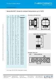
Abmessungen<br />
Die Abmessungen in der Tabelle gelten für einen einzelnen<br />
Helixresonator. Die Breite eines Zwei- bzw.<br />
eines Dreikreisfilters ergibt sich aus dem doppelten<br />
bzw. dreifachen Wert von "a".<br />
Dimensional data<br />
The values in the table are given for one unit (one<br />
helix circuit). In the case of double or triple tuned<br />
units the physical dimensions should be calculated<br />
by multiplying the values respectively.<br />
Type a b c d<br />
7 ... E 7,5 12,5 3,5 2,5<br />
7 ... E/C 7,5 14 3,5 2,5<br />
7 ... G 7,5 12,5 3,5 2,25<br />
10 ... E 10 15,5 3,5 3,2<br />
10 ... E/C 10 16 3,5 3,2<br />
3.09
3<br />
Filter / Spulen / Bausätze / Kunststoff<strong>teil</strong>e<br />
Filters / Coil Assemblies / Thermoplastic Parts<br />
Helixkreise, -Bandfilter<br />
der Reihe 7 und 10<br />
Filter für Geräte der Kommunikationstechnik im<br />
Frequenzbereich 320 MHz bis 2500 MHz<br />
Helix bandpass filters<br />
7 and 10<br />
Components for telecommunication systems in the<br />
range of 320 MHz up to 2500 MHz<br />
Beschreibung der E/C und G-Ausführung<br />
In der E/C und G - Ausführung - für 770 bis 2500<br />
MHz - ist die Abgleichsschraube elektrisch mit dem<br />
Abschirmbecher verbunden. Deshalb beeinflusst ein<br />
metallisches Abgleichwerkzeug die eingestellte Frequenz<br />
nicht.<br />
Die Anpassung an 50 Ω erfolgt über eine Leiterschleife<br />
auf einer kleinen Leiterplatte. Diese ist im<br />
Filter eingebaut.<br />
Description of E/C and G-type<br />
In the E / C and G - type for 770 to 2500 MHz the<br />
tuning screw is connected to the can in a brass nut<br />
and the 50 Ω matching point on a small PC board is<br />
integrated into the helix filter itself.<br />
Because of the good connection between screw and<br />
screening can a metallic trimming tool does not affect<br />
the frequency.<br />
Eigenschaften<br />
Lötbarkeit nach DIN IEC 68-2-20 Ta:<br />
235°C, 5 Sek.<br />
Lötwärmebeständigkeit -2-20 Tb:<br />
260°C, 5 Sek.<br />
Zulässige Betriebstemperatur:<br />
-25°C bis + 85°C<br />
Temperaturkoeffizient von -25°C bis + 85°C:<br />
ca. 50 x 10 -6 / K<br />
Characteristic properties<br />
Solderability as per DIN IEC 68-2-20 Ta:<br />
235°C, 5 sec.<br />
Resistance to soldering heat -2-20 Tb:<br />
260°C, 5 sec.<br />
Permissible working temperature:<br />
-25°C bis + 85°C<br />
Temperature coefficient between<br />
-25°C bis + 85°C:<br />
ca. 50 x 10 -6 / K<br />
Für Ihre Anfrage können Sie das Formblatt auf Seite<br />
3.47 benutzen.<br />
Use the form on page 3.47 for your inquiry.<br />
3.10
3<br />
Filter / Spulen / Bausätze / Kunststoff<strong>teil</strong>e<br />
Filters / Coil Assemblies / Thermoplastic Parts<br />
Helixkreise,<br />
-Bandfilter der<br />
Reihe 7 und 10<br />
Einzelkreise*<br />
Helix bandpass<br />
filters 7 and 10<br />
resonant circuits*<br />
1 1.1<br />
Windungszahl Aufbau Wicklungsrichtung Anschluss an Stift Typ Art.-Nr.<br />
turns arrangement winding direction connection to pin type part number<br />
f [MHz] Q rechts links E Masse<br />
min. ca. max. clockwise anticlockwise in gnd<br />
11,5 276 306 250 1 X 1 10.1 E/C 00 6831 60<br />
13 305 315 200 1 X 1 10.1 E 00 6833 00<br />
10 368 400 220 1 X 1 10.1 E 00 6830 01<br />
10 390 406 200 1 X 1 7.1 E/C 00 5195 80<br />
9,5 420 444 200 1 X 2 7.1 E/C 00 5117 80<br />
9,5 420 444 200 1 X 1 7.1 E/C 00 5117 81<br />
10,5 438 468 220 1 X 1 7.1 E 00 5196 34<br />
10,5 438 468 220 1 X 1 7.1 E 00 5196 35<br />
9 448 474 200 1 X 2 7.1 E/C 00 5119 80<br />
10 448 478 220 1 X 1 7.1 E 00 5195 32<br />
10 448 478 220 1 X 2 7.1 E 00 5144 40<br />
10 458 488 220 1 X 2 7.1 E 00 5195 34<br />
10 458 488 220 1 X 2 7.1 E 00 5144 35<br />
10 458 488 220 1 X 1 7.1 E 00 5195 30<br />
9,5 474 514 220 1 X 1 7.1 E 00 5117 34<br />
9,5 480 520 220 1 X 1 7.1 E 00 5117 30<br />
9,5 480 520 220 1 X 2 7.1 E 00 5117 31<br />
9 500 540 220 1 X 1 7.1 E 00 5119 30<br />
9 500 540 220 1 X 2 7.1 E 00 5121 30<br />
8,5 505 533 200 1.1 X 1 4 7.1 E/C 00 5149 80<br />
8 520 573 200 1.1 X 1 4 7.1 E/C 00 5194 80<br />
8 558 598 220 1 X 2 7.1 E 00 5194 30<br />
8 558 598 220 1 X 1 7.1 E 00 5194 60<br />
7,5 591 630 200 1 X 2 7.1 E 00 5147 30<br />
5,5 780 845 250 1 X 2 7.1 G 00 5102 12<br />
* Zur Anpassung empfehlen wir 1/2 oder 3/4 Windung<br />
als Leiterbahn auf der gedruckten Schaltung.<br />
Dadurch erniedrigt sich die Resonanzfrequenz um<br />
ca. 4 ÷ 6%.<br />
* For matching input and output we recommend to<br />
continue the Helix at the printed circuit board with<br />
1/2 or 3/4 of a turn. In this case a decrease of<br />
frequency must be taken into account. 4 ÷ 6%.<br />
3.11<br />
Directive RoHS<br />
2002/95/EG compliant<br />
pb
3<br />
Filter / Spulen / Bausätze / Kunststoff<strong>teil</strong>e<br />
Filters / Coil Assemblies / Thermoplastic Parts<br />
Helixkreise,<br />
-Bandfilter der<br />
Reihe 7 und 10<br />
Bandfilter*<br />
Leerlaufgüte Q 200<br />
Wicklungsrichtung links<br />
Helix bandpass<br />
filters 7 and 10<br />
bandpass filter*<br />
unloaded Q 200<br />
winding direction<br />
anti clockwise<br />
Windungszahl Durchmesser der Koppelöffnung Anschluss an Stift Typ Artikelnummer<br />
turns f Diameter of coupling window connection to pin type part number<br />
[MHz] E Masse A Masse<br />
min. ca. max. in gnd out gnd<br />
9 395 440 6,5 4 21 10.2 E 00 6829 20<br />
10,5 435 460 3,8 4 21 7.2 E 00 5196 44<br />
10,5 438 460 5,3 4 21 7.2 E 00 5196 45<br />
8 445 490 6,5 5 22 10.2 E 00 6828 20<br />
10,5 445 470 3,8 4 21 7.2 E 00 5196 30<br />
10,5 445 470 3,8 4 22 7.2 E 00 5196 36<br />
10 455 480 3,8 4 21 7.2 E 00 5144 75<br />
10 465 490 3,8 4 21 7.2 E 00 5144 30<br />
10 465 490 4,3 5 22 7.2 E 00 5144 33<br />
10 465 490 3,8 4 22 7.2 E 00 5144 38<br />
10 465 490 3,8 5 22 7.2 E 00 5144 39<br />
10 465 490 4,3 4 22 7.2 E 00 5144 45<br />
7,5 470 515 6,5 5 22 10.2 E 00 6827 75<br />
9,5 490 515 4,8 4 22 7.2 E 00 5117 40<br />
9 510 535 4,3 4 21 7.2 E 00 5121 35<br />
* Zur Anpassung empfehlen wir 1/2 oder 3/4 Windung<br />
als Leiterbahn auf der gedruckten Schaltung.<br />
Dadurch erniedrigt sich die Resonanzfrequenz um<br />
ca. 4 ÷ 6%.<br />
Der Durchmesser der Koppelöffnung und die<br />
Anpassung der Resonatoren bestimmen die<br />
Bandbreite der Filter. Das kleinste Koppelloch und<br />
eine kurze Leiterbahn führen zu kleinster Bandbreite<br />
(unterkritische Kopplung).<br />
Daten gelten für eine Verlängerung auf der<br />
Leiter platte von ca. 3/4 Windungen.<br />
* For matching input and output we recommend to<br />
continue the Helix at the printed circuit board with<br />
1/2 or 3/4 of a turn. In this case a decrease of frequency<br />
must be taken into account. 4 ÷ 6%.<br />
The diameter of the coupling window and the matching<br />
impedance for the resonators determine the<br />
bandwidth of the filter. The smallest coupling<br />
window and a short conducting line on the pc board<br />
produces a narrow bandwidth (the coupling is below<br />
the critical value).<br />
Data are valid for 3/4 of a turn on the PC board as<br />
matching impedance.<br />
3.12<br />
Directive RoHS<br />
2002/95/EG compliant<br />
pb
3<br />
Filter / Spulen / Bausätze / Kunststoff<strong>teil</strong>e<br />
Filters / Coil Assemblies / Thermoplastic Parts<br />
Helixkreise,<br />
-Bandfilter der<br />
Reihe 7 und 10<br />
Bandfilter*<br />
Leerlaufgüte Q 200<br />
Wicklungsrichtung links<br />
Helix bandpass<br />
filters 7 and 10<br />
bandpass filter*<br />
unloaded Q 200<br />
winding direction<br />
anti clockwise<br />
Durchmesser der<br />
Anschluss an Stift<br />
Windungs- Abgleich ca. f a 0 Koppelöffnung B connection to pin Type Art.-Nr.<br />
zahl [MHz] [MHz] [dB] diameter of [MHz] E Masse A Masse<br />
turns adj. to min. max. max. coupling window -3 dB in gnd out gnd type part number<br />
11 310 270 310 3,3 4,5 4 24 10.2 E/C 00 6831 30<br />
10,5 370 365 370 2,2 9 4 24 7.2 E/C 00 5196 81<br />
9 387 370 390 1,4 12 4 24 10.2 E/C 00 6829 30<br />
10 398 380 400 3,8 5 4 24 7.2 E/C 00 5144 90<br />
8,5 408 390 410 1,4 13 4 24 10.2 E/C 00 6828 80<br />
9,5 430 405 430 4,5 5 4 24 7.2 E/C 00 5117 90<br />
10,5 435 460 4,5 1 24 7.2 E 00 5196 37<br />
10,5 435 460 4,1 4 21 7.2 E 00 5196 38<br />
10,5 435 460 4,5 1 22 7.2 E 00 5196 39<br />
10,5 435 460 4,1 2 22 7.2 E 00 5196 40<br />
10,5 435 460 4,5 2 22 7.2 E 00 5196 43<br />
10,5 435 460 4,1 1 21 7.2 E 00 5196 48<br />
10,5 435 460 4,5 5 22 7.2 E 00 5196 70<br />
10,5 440 465 4,1 1 21 7.2 E 00 5196 47<br />
10,5 445 470 4,1 1 21 7.2 E 00 5196 46<br />
10,5 445 470 4,5 2 22 7.2 E 00 5196 41<br />
10,5 445 470 4,5 5 22 7.2 E 00 5196 42<br />
10,5 445 470 4,1 2 22 7.2 E 00 5196 49<br />
10 455 480 4,5 1 22 7.2 E 00 5144 48<br />
10 455 480 4,1 2 22 7.2 E 00 5144 49<br />
10 455 480 4,1 4 21 7.2 E 00 5144 42<br />
10 460 485 4,1 2 22 7.2 E 00 5144 73<br />
10 460 485 4,1 1 21 7.2 E 00 5144 74<br />
10 465 490 4,5 1 24 7.2 E 00 5144 34<br />
10 465 490 4,5 2 22 7.2 E 00 5144 37<br />
10 465 490 4,1 4 21 7.2 E 00 5144 44<br />
10 465 490 4,1 2 22 7.2 E 00 5144 46<br />
10 465 490 4,5 1 22 7.2 E 00 5144 47<br />
10 465 490 4,5 5 22 7.2 E 00 5144 71<br />
10 465 490 4,1 1 21 7.2 E 00 5144 72<br />
9,5 490 515 4,5 5 22 7.2 E 00 5117 36<br />
9,5 490 515 4,5 1 21 7.2 E 00 5117 37<br />
9,5 490 515 4,1 1 21 7.2 E 00 5117 38<br />
* Zur Anpassung empfehlen wir 1/2 oder 3/4 Windung<br />
als Leiterbahn auf der gedruckten Schaltung.<br />
Dadurch erniedrigt sich die Resonanzfrequenz um<br />
ca. 4 ÷ 6%.<br />
Der Durchmesser der Koppelöffnung und die<br />
Anpassung der Resonatoren bestimmen die Bandbreite<br />
der Filter. Das kleinste Koppelloch und eine<br />
kurze Leiterbahn führen zu kleinster Bandbreite<br />
(unterkritische Kopplung).<br />
Daten gelten für eine Verlängerung auf der<br />
Leiter platte von ca. 3/4 Windungen.<br />
3.13<br />
* For matching input and output we recommend to<br />
continue the Helix at the printed circuit board with<br />
1/2 or 3/4 of a turn. In this case a decrease of frequency<br />
must be taken into account. 4 ÷ 6%.<br />
The diameter of the coupling window and the matching<br />
impedance for the resonators determine the<br />
bandwidth of the filter. The smallest coupling window<br />
and a short conducting line on the pc board<br />
produces a narrow bandwidth (the coupling is below<br />
the critical value).<br />
Data are valid for 3/4 of a turn on the pc board as<br />
matching impedance.<br />
Directive RoHS<br />
2002/95/EG compliant<br />
pb
3<br />
Filter / Spulen / Bausätze / Kunststoff<strong>teil</strong>e<br />
Filters / Coil Assemblies / Thermoplastic Parts<br />
Helixkreise,<br />
-Bandfilter der<br />
Reihe 7 und 10<br />
Bandfilter<br />
mit Anpassung 50 Ω<br />
Helix bandpass<br />
filters 7 and 10<br />
bandpass filter<br />
with tap 50 Ω<br />
Abgleich f B ≥ a 0 ≤ Anschluss an Stift Type Selektion Art.-Nr.<br />
[MHz] [MHz] [MHz] [dB] connection to pin type selection part number<br />
adj. to min. max. -1dB -3dB E Masse A Masse a ≥ - ∆f a ≥ + ∆f<br />
in gnd out gnd [dB] [MHz] [dB] [MHz]<br />
305 305 340 Daten a.Anfrage 4 5 21 22 10.2 E data on request 00 6833 10<br />
315 10 2,2 5 1 22 24 7.2 E / C 30 40 28 40 **) 00 5196 85<br />
340 320 345 3 4,2 4 2 21 25 10.2 E / C 22 8 20 8 00 6830 70<br />
365 365 420 14 2,2 5 1 22 24 10.2 E 22 30 18 30 00 6830 11<br />
390 370 400 12,5 1,6 5 1 22 24 7.2 E / C 26 30 21 30 00 5196 95<br />
395 395 440 10 2,2 4 5 21 22 10.2 E 28 30 23 30 00 6829 10<br />
412 405 420 11 1,8 5 1 22 24 7.2 E / C 24 30 20 30 00 5144 95<br />
418 405 430 5,5 9,2 4 5 1 22 24 7.2 E / C 34 40 25 40 **) 00 5104 01<br />
432 410 460 12 2 5 2 22 25 7.2 E / C 27 30 22 30 00 5117 60<br />
432 430 450 12 2,2 5 2 22 25 7.2 E 24 30 24 30 00 5196 50<br />
432 430 450 12 2 5 1 22 24 7.2 E 20 30 20 30 00 5196 51<br />
434 410 460 15 1,5 5 1 22 24 7.2 E / C 24 40 20 40 00 5117 65<br />
434 434 474 9 2,5 4 5 21 22 10.2 E 30 30 24 30 00 6828 10<br />
448 440 460 7,5 3,5 5 2 22 25 7.2 E 33 30 28 30 00 5196 52<br />
450 440 490 13 2,1 5 2 22 25 7.2 E / C 25 30 20 30 00 5121 90<br />
454 450 470 13 2,1 5 2 22 25 7.2 E 22 30 22 30 00 5144 50<br />
455 442 468 5,2 8,7 4 5 1 22 24 7.2 E / C 35 40 25 40 **) 00 5104 00<br />
464 456 476 14 2,1 5 2 22 25 7.2 E 20 30 20 30 00 5144 51<br />
484 464 484 15 2 5 2 22 25 7.2 E 20 30 20 30 00 5144 52<br />
502 480 520 11 2,2 5 2 22 25 7.2 E / C 25 30 20 30 00 5149 82<br />
610 9 16 1,8 5 2 22 25 7.2 E / C 16 30 12 30 00 5147 10<br />
816 770 845 28 32 3,6/7 4 5 21 22 7.2 G 16 40 16 40 **) 00 5102 04<br />
836 770 845 27 32 3,3/6,5 4 5 21 22 7.2 G 14 40 14 40 **) 00 5102 05<br />
875 840 915 18 2,2 4 5 21 22 7.2 G 16 40 16 40 **) 00 5102 13<br />
881 850 915 27 32 3,5/7 4 5 21 22 7.2 G 19 40 19 40 **) 00 5102 06<br />
893 850 915 16 2,2 4 5 21 22 7.2 G 16 40 16 40 **) 00 5102 03<br />
906 850 915 27 32 3/4,5 4 5 21 22 7.2 G 12 40 12 40 **) 00 5102 07<br />
914 850 915 16 2,2 4 5 21 22 7.2 G 16 40 16 40 **) 00 5102 02<br />
947 930 990 25 30 2,7/4 4 5 21 22 7.2 G 14 40 14 40 **) 00 5102 08<br />
959 930 990 16 2,2 4 5 21 22 7.2 G 16 40 16 40 **) 00 5102 01<br />
980 930 990 16 2,2 4 5 21 22 7.2 G 16 40 16 40 **) 00 5102 00<br />
992 930 992 31 38 2/3,5 4 5 21 22 7.2 G 10 40 10 40 **) 00 5102 09<br />
1051 1010 1090 18 30 2 4 5 21 22 7.2 G 15 50 12 50 **) 00 5102 30<br />
1502 25 3,5 4 5 21 22 7.2 G 30 100 25 100 **) 00 5102 35<br />
1575 1550 1640 33 2,8 4 5 21 22 7.2 G 35 100 28 100 **) 00 5102 38<br />
1625 1550 1640 33 2,6 4 5 21 22 7.2 G 35 100 28 100 **) 00 5102 36<br />
1690 1640 1740 35 2,5 4 5 21 22 7.2 G 35 100 25 100 **) 00 5102 37<br />
2000 1900 2000 45 2,5 4 5 21 22 7.2 G 20 200 20 200 **) 00 5102 40<br />
2450 2350 2450 65 2 4 5 21 22 7.2 G 20 200 20 200 **) 00 5102 41<br />
**) Raster 2,25 **) grid 2,25<br />
3.14<br />
Directive RoHS<br />
2002/95/EG compliant<br />
pb
3<br />
Filter / Spulen / Bausätze / Kunststoff<strong>teil</strong>e<br />
Filters / Coil Assemblies / Thermoplastic Parts<br />
Helixkreise,<br />
-Bandfilter der<br />
Reihe 7 und 10<br />
Bandfilter mit<br />
unterschiedlicher<br />
Anpassung<br />
Helix bandpass<br />
filters 7 and 10<br />
bandpass filter with<br />
various matching<br />
impedance<br />
Abgleich f B ≥ a0 ≤ Anschluss an Stift Impendanz Selektion Art.-Nr.<br />
[MHz] [MHz] [MHz] [dB] connection to pin [Ω] selection part number<br />
adj. to min. max. -3dB E Masse A Masse a ≥ - ∆ f a ≥ + ∆ f<br />
in gnd out gnd in out [dB] [MHz] [dB] [MHz]<br />
400 395 415 11 2,4 4 2 21 22 150 50 25 30 25 30 00 5196 67<br />
415 415 435 12 1,8 4 5 21 22 50 50 20 30 20 30 00 5196 61<br />
418 415 435 13 2,2 4 2 21 22 150 50 22 30 22 30 00 5196 63<br />
420 400 420 18 1,7 5 1 22 24 300 50 17 30 17 30 00 5196 66<br />
420 415 435 12 1,8 5 1 21 22 50 50 20 30 20 30 00 5196 68<br />
428 428 448 6,5 3,4 4 5 21 22 300 50 33 30 30 30 00 5196 62<br />
438 438 458 8,5 1,8 4 2 21 22 150 50 32 30 28 30 00 5196 60<br />
440 438 458 8,5 1,8 5 4 21 22 150 50 32 30 28 30 00 5196 64<br />
Abgleich f B ≥ a 0 ≤ Anschluss an Stift Impendanz Selektion Art.-Nr.<br />
[MHz] [MHz] [MHz] [dB] connection to pin [Ω] selection part number<br />
adj. to min. max. -3dB E Masse A Masse a ≥ - ∆ f a ≥ + ∆ f<br />
in gnd out gnd in out [dB] [MHz] [dB] [MHz]<br />
445 438 458 14 2,2 5 1 22 21 50 150 26 40 20 40 00 5196 65<br />
3.15<br />
Directive RoHS<br />
2002/95/EG compliant<br />
pb
3<br />
Filter / Spulen / Bausätze / Kunststoff<strong>teil</strong>e<br />
Filters / Coil Assemblies / Thermoplastic Parts<br />
Helixkreise,<br />
-Bandfilter der<br />
Reihe 7 und 10<br />
Bandfilter<br />
mit Anpassung 50 Ω<br />
Helix bandpass<br />
filters 7 and 10<br />
bandpass filter<br />
with tap 50 Ω<br />
Abgleich f B ≥ a 0 ≤ Anschluss an Stift Type Selektion Art.-Nr.<br />
[MHz] [MHz] [MHz] [dB] connection to pin type selection part number<br />
adj. to min. max. -1dB -3dB E Masse Z Masse A Masse a ≥ - ∆ f a ≥ + ∆ f<br />
in gnd tap gnd out gnd [dB] [MHz] [dB] [MHz]<br />
397 385 409 6,2 8,5 5 5 1 - 22 32 34 7.3 E / C 45 40 36 40 *1) 00 5105 03<br />
408 408 448 24 2,1 4 *) - 22 32 *) 10.3 E 37 40 28 40 00 6828 60<br />
418 406 430 6,9 9 5 5 1 - 22 32 34 7.3 E / C 46 40 35 40 *1) 00 5105 02<br />
430 430 470 2,3 27 2 4 *) - 22 32 *) 10.3 E 30 40 24 40 00 6828 35<br />
433 420 446 6,5 9,5 4,5 5 1 - 22 32 34 7.3 E / C 42 40 34 40 *1) 00 5105 01<br />
445 445 490 16 2,7 4 2 24 22 34 32 10.3 E 40 40 40 40 00 6828 40<br />
455 442 468 4,5 7 5 5 1 - 22 32 34 7.3 E / C 45 40 34 40 *1) 00 5105 00<br />
460 8 3,3 5 2 - 24 32 35 7.3 E / C 40 30 40 40 00 5117 55<br />
462 450 470 5,8 8,5 3,4 5 2 - 24 32 35 7.3 E / C 42 40 42 40 00 5121 95<br />
463 455 500 7,5 12 2,5 2 *) - 22 32 *) 10.3 E 28 30 25 40 00 6827 80<br />
465 465 510 14 17 2,4 4 2 24 22 34 32 10.3 E 40 40 37 40 00 6827 85<br />
480 464 484 25 2,5 5 4 - 22 32 31 7.3 E 18 40 15 40 00 5144 60<br />
480 464 484 34 2,5 5 4 - 22 32 31 7.3 E 10 40 10 40 00 5144 61<br />
480 464 484 14 2,5 5 1 - 22 32 34 7.3 E 30 40 30 40 00 5144 62<br />
480 464 484 20 2,5 5 4 - 22 32 31 7.3 E 24 40 20 40 00 5144 63<br />
500 490 510 6,5 9 3,2 5 2 - 24 32 35 7.3 E / C 36 25 32 25 00 5149 90<br />
558 530 558 11 15 2,3 5 2 - 24 32 35 7.3 E / C 36 40 33 40 00 5194 91<br />
575 550 575 10 15 2,5 5 2 - 24 32 35 7.3 E / C 36 40 30 40 00 5194 90<br />
605 585 619 10 15 2 5 2 - 24 32 35 7.3 E / C 35 40 31 40 00 5197 91<br />
619 585 619 10 15 1,9 5 2 - 24 32 35 7.3 E / C 32 40 31 40 00 5197 90<br />
644 624 644 10 15 2,1 5 2 - 24 32 35 7.3 E / C 31 40 30 40 00 5197 40<br />
711 9,5 13 3,5 5 1 - 21 32 34 7.3 E / C 47 40 44 40 00 5146 10<br />
902 880 915 25 4 5 - 22 31 32 7.3 G 24 40 24 40 *1) 00 5103 03<br />
914 880 915 16 3,6 4 5 - 22 31 32 7.3 G 30 40 30 40 *1) 00 5103 01<br />
947 945 980 28 3 4 5 - 22 31 32 7.3 G 20 40 20 40 *1) 00 5103 02<br />
959 945 980 16 3,6 4 5 - 22 31 32 7.3 G 30 40 30 40 *1) 00 5103 00<br />
960 945 980 22 3,3 4 5 - 22 31 32 7.3 G 29 40 29 40 *1) 00 5103 04<br />
1747,5 75 4/2,5/4 4 5 - 22 31 32 7.3 G 20 95 15 95 *1) 00 5103 50<br />
1842,5 75 3 4 5 - 22 31 32 7.3 G 20 95 15 95 *1) 00 5103 51<br />
*1) Raster 2,25 mm<br />
*1) grid 2,25 mm<br />
* Zur Anpassung empfehlen wir 1/2 oder 3/4 Windung<br />
auf der gedruckten Schaltung als Leiterbahn.<br />
* For matching input and output we recommend to<br />
continue the Helix at the printed circuit board with<br />
1/2 or 3/4 of a turn.<br />
3.16<br />
Directive RoHS<br />
2002/95/EG compliant<br />
pb
3<br />
Filter / Spulen / Bausätze / Kunststoff<strong>teil</strong>e<br />
Filters / Coil Assemblies / Thermoplastic Parts<br />
SMD – Helix-Filter<br />
Kennzeichen:<br />
Abgeglichen auf<br />
Mittenfrequenz<br />
Niedrige Einfügunsdämpfung<br />
Hohe Selektion<br />
Kompakte flache Bauform<br />
Anwendungen:<br />
Mobilfunk<br />
Satelliten-TV<br />
Cityruf<br />
Bündelfunk<br />
Betriebsfunk<br />
Funkfernsteuerung<br />
Daten:<br />
Frequenzbereich:<br />
SM-H82H: 180 - 380 MHz<br />
SM-H82: 370 - 700 MHz<br />
Betriebstemperaturbereich:<br />
-40°C bis + 125°C<br />
Lötwärmebeständigkeit:<br />
260°C, 10 Sek.<br />
Zul.Eingangsleistung: ca. 5 W<br />
Empfohlene Löttechnik:<br />
Reflow and vapor phase<br />
Verpackung siehe Seite 4.115:<br />
Blisterpack IEC 286/3<br />
SM-H82<br />
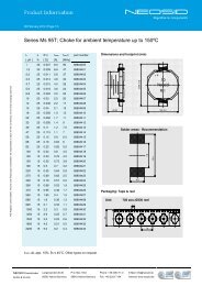
Abmessungen und Empfehlung<br />
für Lötflächenmaße (mm):<br />
SM-H82H<br />
Dimensions and recommended<br />
pad pattern (mm):<br />
SMD – Helical filter<br />
Features:<br />
Tuned to center frequency<br />
Low insertion loss<br />
High selectivity<br />
Compact flat design<br />
Applications:<br />
Mobile radio<br />
Satellite TV<br />
Paging systems<br />
Trunked radio<br />
Private mobile radio<br />
Remote control<br />
Data:<br />
Frequency range:<br />
SM-H82H: 180 - 380 MHz<br />
SM-H82: 370 - 700 MHz<br />
Operating temperature range:<br />
-40°C to + 125°C<br />
Soldering heat resistance:<br />
260°C, 10 sec.<br />
Max. input power: approx. 5 W<br />
Recommended soldering method:<br />
Reflow and vapor phase<br />
Packaging see page 4.115:<br />
Blisterpack IEC 286/3<br />
Typische Werte für<br />
2-kreisige Bandpassfilter/<br />
Typical values for a<br />
2.resonator bandpass filters:<br />
f 0 a 0 Bw(-1dB) Bw(-3dB) a(-40MHz) a(+40MHz) Art.-Nr.<br />
[MHz] [dB] ≥ [MHz] ≥ [MHz] [dB] [dB] Part number<br />
227*) 5,9 0,8 2,2 34 31 00 5618 15<br />
230*) 5,1 2,2 7,2 30 32 00 5618 20<br />
380 2 15 24 35 20 00 5615 00<br />
398 2,4 11 16 30 20 00 5615 03<br />
404 2,5 11 15 30 22 00 5615 04<br />
412 2,6 7 11 28 22 00 5615 08<br />
432 2,4 7,5 13,5 26 20 00 5615 11<br />
434 2,4 7,5 13,5 26 20 00 5615 12<br />
450 2,4 10 15 25 19 00 5615 16<br />
455 2,4 10 15 24 18 00 5615 19<br />
465 2,3 11 18 23 18 00 5615 22<br />
470 2,1 12 19 23 18 00 5615 25<br />
*) SM-H82H<br />
Bandpassfilter mit<br />
3 Resonatoren (SM-H83) bzw.<br />
mit 1 Resonator (SM-H81) sind<br />
ebenfalls lieferbar./<br />
We can also supply<br />
bandpass filters with<br />
3 resonators (SM-H83) or with<br />
1 resonator (SM-H81).<br />
3.17<br />
Directive RoHS<br />
2002/95/EG compliant<br />
pb
3<br />
Filter / Spulen / Bausätze / Kunststoff<strong>teil</strong>e<br />
Filters / Coil Assemblies / Thermoplastic Parts<br />
Helixantennen<br />
433 MHz / 868 MHz / 2,4 GHz<br />
Helix antennas<br />
433 MHz / 868 MHz / 2,4 GHz<br />
Anwendung:<br />
HF Technik<br />
Receiver / Transmitter<br />
Kennzeichen:<br />
Kompakte Bauform<br />
Mechanische Stabilität<br />
Geringe elektrische Toleranzen<br />
Automatisch bestückbar<br />
Verpackung:<br />
Stangenmagazin, kundenspezifisch<br />
Application:<br />
RF circuits<br />
Receivers / transmitters<br />
Features:<br />
Compact design<br />
Mechanical stability<br />
Tight electrical tolerances<br />
Suitable for automatic insertion<br />
Packaging:<br />
Stack, customized<br />
Neuheit<br />
new<br />
Weitere Typen auf Anfrage/<br />
Other types on request<br />
3.18<br />
Directive RoHS<br />
2002/95/EG compliant<br />
pb
3<br />
Filter / Spulen / Bausätze / Kunststoff<strong>teil</strong>e<br />
Filters / Coil Assemblies / Thermoplastic Parts<br />
Abgleichbare HF-Spulen<br />
Filter für die Oberflächenmontage<br />
Adjustable RF coils<br />
Filter coils for surface mounting technology<br />
Für die Oberflächenmontage liefern wir abgleichbare<br />
Spulen SMF 5.1 in einer Reihe von unterschiedlichen<br />
Ausführungen. Sie eigenen sich besonders für<br />
den Frequenzbereich von 10 MHz bis 200 MHz.<br />
Unterhalb von 10 MHz nehmen die Gütewerte ab,<br />
da aufgrund der höheren Induktivitäten der Gleichstromwiderstand<br />
stark zunimmt.<br />
Wir empfehlen die Anwendung in Geräten der Funk-/<br />
Nachrichtentechnik, Sender und Empfänger, HF-<br />
Eingangsmodulen, Antennenverstäkern, Übergangsanlagen<br />
für Kabelfernsehen und Satellitenübergabestationen.<br />
Die abgleichbare Spule SMF 5.1 hat einen temperaturfesten<br />
Spulenkörper und wird mit einem Ferritnippelkern<br />
abgestimmt. Ein Kupferbecher sorgt für eine<br />
gute Abschirmung. Max. 5 Anschlüsse sind möglich.<br />
As surface mount device we deliver adjustable filter<br />
coils SMF 5.1 in several different configurations.<br />
These coils are designed for the frequency range 10<br />
MHz up to 200 MHz. Below 10 MHz the Q factor<br />
decreases as there is a substantial increase in the DC<br />
resistance caused by the higher inductances.<br />
We recommend the application in all kind of equipment<br />
for communications, receiver and transmitter<br />
sets, in RF front end circuits, aerial amplifier, switch<br />
over circuits for cable tv and satellite systems.<br />
The adjustable coil SMF 5.1 has a heat resistant bobbin<br />
and may be adjusted with a ferrite nipple core. A<br />
copper screening can gives a high value of shielding.<br />
It is possible to use all 5 terminations of the coil.<br />
Allgemeine Daten der Reihe SMF 5.1<br />
Abmessungen: 5 x 5 x 5 mm<br />
Verpackung im Foliengurt:<br />
16 mm IEC Publ. 286 / 3<br />
oder auf Wunsch auf Paletten<br />
Empfohlene Löttechnik: Reflow<br />
Lötwärmebeständigkeit der Anschlüsse:<br />
260° C 10 sek.<br />
Betriebstemperaturbereich: - 40°C bis + 85°C<br />
Feuchteklasse: F / DIN 40 040<br />
Induktivitätsbereich: 20 nH ... 600 µH<br />
Abgleichbarkeit: ± 7,5 % / ± 5 % mit F100b<br />
Anwendungsfrequenz: 0,5 MHz ÷ 200 MHz<br />
Induktivität bei + 23° C, 50 mV eff am Messobjekt<br />
und Frequenz wie angegeben.<br />
Weitere allgemeine Angaben finden Sie in Teil 4.<br />
3.19<br />
General data of type SMF 5.1<br />
Dimensions: 5 x 5 x 5 mm<br />
Taped in plastic foil: 16 mm IEC Publ. 286 / 3<br />
or on request on palettes<br />
Recommended soldering methods: Reflow<br />
Soldering heat resistance of soldering tags:<br />
260° C 10 sec.<br />
Operating temperature range: - 40° C to + 85° C<br />
Humidity class: F / DIN 40 040<br />
Inductance range: 20 nH ... 600 µH<br />
Adjusting range: ± 7,5 % / ± 5 % with Ferrite F100b<br />
Frequency range: 0,5 MHz ÷ 200 MHz<br />
Inductance at + 23°C, 50 mV eff across the inductor<br />
and frequency as listed.<br />
You can find further general information in part 4.<br />
Directive RoHS<br />
2002/95/EG compliant<br />
pb
3<br />
Filter / Spulen / Bausätze / Kunststoff<strong>teil</strong>e<br />
Filters / Coil Assemblies / Thermoplastic Parts<br />
Standardwerte<br />
E - 12<br />
Reihe der SMF 5.1,<br />
1Wicklung<br />
Standard values<br />
E - 12<br />
Typ SMF 5.1, 1 winding<br />
L bei f L Bereich Abgleichbereich Q bei f Anschluss an Stift Windung Artikelnummer<br />
[µH] at [MHz] range adjustment range ≥ at [MHz] connection to pin turns part number<br />
[MHz] A E<br />
0,047 10 50 ÷ 200 ± 3 % 38 150 4 2 3 1 / 4 00 5601 00<br />
0,056 10 50 ÷ 200 -6% 40 150 2 4 3 3 / 4 00 5601 01<br />
0,068 10 50 ÷ 200 ± 3 % 45 150 2 4 3 3 / 4 00 5601 02<br />
0,082 10 50 ÷ 200 ± 3,5 % 38 150 2 4 4 3 / 4 00 5601 03<br />
0,1 10 50 ÷ 200 ± 4 % 48 100 2 4 4 3 / 4 00 5601 04<br />
0,12 10 50 ÷ 200 ± 5 % 32 100 2 4 5 3 / 4 00 5601 05<br />
0,15 10 50 ÷ 200 ± 5 % 42 100 2 4 5 3 / 4 00 5601 06<br />
0,18 10 50 ÷ 200 ± 5 % 40 100 4 2 6 1 / 4 00 5601 07<br />
0,22 10 20 ÷ 150 ± 7,5 % 45 70 4 2 7 1 / 4 00 5601 08<br />
0,27 10 20 ÷ 150 ± 7,5 % 35 70 2 4 7 3 / 4 00 5601 09<br />
0,33 10 20 ÷ 150 ± 7,5 % 35 70 2 4 8 3 / 4 00 5601 10<br />
0,39 10 20 ÷ 150 ± 7,5 % 40 70 2 4 9 3 / 4 00 5601 11<br />
0,47 10 20 ÷ 150 ± 7,5 % 45 70 4 2 11 1 / 4 00 5601 12<br />
0,56 10 20 ÷ 150 ± 7,5 % 42 70 2 4 12 3 / 4 00 5601 13<br />
0,68 10 10 ÷ 100 ± 7,5 % 45 50 4 2 14 1 / 4 00 5601 14<br />
0,82 10 10 ÷ 100 ± 7,5 % 42 50 2 4 15 3 / 4 00 5601 15<br />
1 10 2 ÷ 40 ± 7,5 % 42 50 4 2 17 1 / 4 00 5601 16<br />
1,2 10 2 ÷ 40 ± 7,5 % 45 20 4 2 19 1 / 4 00 5601 17<br />
1,5 10 2 ÷ 40 ± 7,5 % 45 20 4 2 21 1 / 4 00 5601 18<br />
1,8 10 2 ÷ 40 ± 7,5 % 45 20 2 4 23 3 / 4 00 5601 19<br />
2,2 1 2 ÷ 40 ± 5 % 45 20 2 4 27 3 / 4 00 5601 20<br />
2,7 1 2 ÷ 40 ± 5 % 40 20 4 2 30 1 / 4 00 5601 21<br />
3,3 1 2 ÷ 40 ± 5 % 35 20 4 2 34 1 / 4 00 5601 22<br />
3,9 1 2 ÷ 40 ± 5 % 35 10 2 4 34 3 / 4 00 5601 23<br />
4,7 1 2 ÷ 40 ± 5 % 35 10 2 4 38 3 / 4 00 5601 24<br />
5,6 1 2 ÷ 40 ± 5 % 35 10 2 4 41 3 / 4 00 5601 25<br />
6,8 1 1 ÷ 10 ± 5 % 30 5 4 2 44 1 / 4 00 5601 26<br />
8,2 1 1 ÷ 10 ± 5 % 23 5 4 2 48 1 / 4 00 5601 27<br />
10 1 1 ÷ 10 ± 5 % 23 5 4 2 55 1 / 4 00 5601 28<br />
12 1 1 ÷ 10 ± 5 % 23 5 4 2 61 1 / 4 00 5601 29<br />
15 0,5 1 ÷ 10 ± 5 % 25 5 4 2 67 1 / 4 00 5600 19<br />
3.20<br />
Directive RoHS<br />
2002/95/EG compliant<br />
pb
3<br />
Filter / Spulen / Bausätze / Kunststoff<strong>teil</strong>e<br />
Filters / Coil Assemblies / Thermoplastic Parts<br />
Sondertypen<br />
Reihe SMF 5.1<br />
1 2<br />
Special types<br />
Typ SMF 5.1<br />
3 4<br />
Abgleich- Anschluss Windungs- Windungszahl Bild Art.-Nr.<br />
L bei f L Bereich bereich Q bei f der Wicklung zahl bis Anzapf<br />
[µH] at [MHz] range adjustment ≥ at [MHz] connection no. of turns turns to tab picture part number<br />
[MHz] range of winding<br />
A1 E1 A2 E2 Z n1 n2<br />
0,014 10 100 ÷ 200 ± 3 % 65 200 4 2 - - - 1 1 / 4 - - 1 00 5600 18<br />
0,092 10 50 ÷ 200 ± 5 % 40 100 4 2 - - - 4 1 / 4 - - 1 00 5600 57<br />
0,117 1 20 ÷ 200 ± 4 % 40 100 2 4 - - - 4 3 / 4 - - 1 00 5600 11<br />
0,137 10 20 ÷ 150 ± 5 % 35 100 4 2 - - - 5 1 / 4 - - 1 00 5600 54<br />
0,17 1 20 ÷ 150 ± 5 % 25 70 2 5 4 3 1 4 1 / 2 6 3 / 4 2 1 / 4 4 00 5600 42<br />
0,24 1 20 ÷ 150 ± 5 % 30 70 1 5 4 2 - 7 1 / 4 5 1 / 4 - 3 00 5600 31<br />
0,24 1 20 ÷ 150 -1,75 30 70 1 5 4 2 - 7 1 / 4 3 1 / 4 - 3 00 5600 32<br />
0,75 10 20 ÷ 150 ± 5 % 25 30 1 2 5 4 - 14 3 / 4 15 1 / 4 - 3 00 5600 39<br />
0,24 13 20 ÷ 150 ± 5 % 30 35 1 5 - - - 7 1 / 4 - - 1 00 5600 04<br />
0,85 1 20 ÷ 150 ± 7,5 % 45 45 2 5 4 3 1 16 1 / 2 2 3 / 4 8 1 / 4 4 00 5600 41<br />
0,97 13 10 ÷ 100 ± 5 % 40 35 4 2 1 5 - 16 2 - 3 00 5600 30<br />
1 1 10 ÷ 100 -7,50% 25 45 2 5 - - 1 18 1 / 2 - 9 1 / 4 2 00 5600 21<br />
1,18 2 10 ÷ 100 ± 5 % 22 40 2 4 5 1 3 18 3 / 4 3 3 / 4 14 1 / 2 4 00 5600 40<br />
1,2 1 10 ÷ 100 16% 38 20 4 2 1 5 - 20 1 / 4 4 1 / 4 - 3 00 5600 37<br />
1,3 1 10 ÷ 100 ± 7,5 % 30 10 5 1 - - - 19 3 / 4 - - 1 00 5600 13<br />
1,35 0,3 10 ÷ 100 ± 5 % 20 26 2 4 5 1 3 18 3 / 4 9 3 / 4 9 1 / 2 4 00 5600 44<br />
1,79 1 1 ÷ 15 +3 / -11 25 12 2 4 5 1 - 22 3 / 4 4 3 / 4 - 3 00 5600 35<br />
2 0,2 5 ÷ 50 ± 5 % 35 21 4 2 - - - 25 1 / 4 - - 1 00 5600 00<br />
2,15 13 5 ÷ 40 ± 7,5 % 45 35 1 5 - - - 26 - - 1 00 5600 05<br />
2,5 13 5 ÷ 40 ± 7,5 % 40 35 1 5 - - - 29 - - 1 00 5600 06<br />
3 0,2 5 ÷ 40 ± 5 % 30 21 2 4 - - 3 30 3 / 4 - 9 1 / 2 2 00 5600 20<br />
3,1 0,2 5 ÷ 40 ± 5 % 32 21 4 2 - - - 32 - - 1 00 5600 01<br />
10,2 0,1 1 ÷ 10 ± 7 % 18 1,6 2 4 5 1 - 55 3 / 4 11 3 / 4 - 3 00 5600 34<br />
19,6 0,1 1 ÷ 10 +10 / -1 24 5 4 2 - - - 78 1 / 4 - - 1 00 5600 56<br />
28 0,1 1 ÷ 10 +4 / -16 18 1,8 2 4 5 1 - 92 3 / 4 18 3 / 4 - 3 00 5600 36<br />
32 1 1 ÷ 10 +20 14 1 1 5 4 2 - 108 1 / 4 36 1 / 4 - 3 00 5600 33<br />
125 0,1 0,5 ÷ 2 ± 7,5 % 18 1 4 2 - - - 208 - - 1 00 5600 09<br />
150 0,03 0,5 ÷ 2 ± 7,5 % 16 1 5 1 4 2 - 217 3 / 4 85 1 / 4 - 3 00 5600 38<br />
390 0,1 0,5 ÷ 2 ± 7,5 % 20 1 1 5 - - - 365 - - 1 00 5600 08<br />
500 0,1 0,5 ÷ 2 ± 7,5 % 12 0,5 4 2 - - - 426 - - 1 00 5600 02<br />
680 0,05 0,5 ÷ 2 ± 7,5 % 12 0,45 4 2 - - - 490 - - 1 00 5600 59<br />
3.21<br />
Directive RoHS<br />
2002/95/EG compliant<br />
pb
3<br />
Filter / Spulen / Bausätze / Kunststoff<strong>teil</strong>e<br />
Filters / Coil Assemblies / Thermoplastic Parts<br />
Abgleichbare HF-Spulen<br />
Adjustable RF coils<br />
Mit Hilfe modernster Wickeltechnik haben wir die<br />
Fabrikation von abgleichbaren HF - Spulen weiter<br />
ausgebaut. So fertigen wir einfache und komplizierte<br />
Ausführungen aus den verschiedenen Bausätzen für<br />
den Frequenzbereich 0,1 bis 200 MHz. Im unteren<br />
Frequenzbereich - bis etwa 15 MHz - eignet sich am<br />
besten der Aufbau 7.1; darüber, je nach elektrischer<br />
Anforderung und zulässiger Bauhöhe, empfehlen wir<br />
die Baugrössen 5.1, 7.1 S, 7.1 K, 7.1 E und 10.1.<br />
Während bei den Spulen der Reihen 7.1 und 10.1<br />
die Anschlussstifte im Raster 2,5 angeordnet sind,<br />
beträgt das Rastermaß für die Bauform 7.1 S, und 7.1<br />
K standardmäßig 2,25 mm. Eine Sonderausführung<br />
in dem jeweils anderen Maß ist nur bei 7.1 und 7.1 S<br />
möglich.<br />
Die Ausführung 5.1 hat ein Raster von 1,8 mm.<br />
Zur Unterscheidung sind die Spulen mit einer mehrstelligen<br />
Zahl bedruckt, oder sie haben eine Farbkennzeichnung.<br />
Detaillierte Angaben über bestimmte, im Katalog<br />
nicht näher beschriebene elektrische oder mechanische<br />
Eigenschaften sind der jeweiligen Bauvorschrift<br />
zu entnehmen, die wir auf Wunsch gern zusenden.<br />
Using the most advanced winding methods we have<br />
further extended our range of adjustable RF coils. We<br />
manufacture both simple and complex coil structures<br />
for the frequency range of 0,1 to 200 MHz. Type 7.1<br />
is most suitable up to about 15 MHz; for higher<br />
frequencies we recommend types 5.1, 7.1 S, 7.1 K,<br />
7.1 E and 10.1 dependent on the electrical specification<br />
and acceptable height.<br />
Coils type 7.1 and 10.1 have pins arranged for<br />
2.5 mm grid, while coils 7.1 S and 7.1 K are<br />
standardized for 2,25 mm grid. Only types 7.1 and<br />
7.1 S can be manufactured of either 2,25 or 2,5 mm<br />
grid.<br />
Type 5.1 has a grid of 1,8 mm.<br />
For easier recognition the coils have printed<br />
multidigital number or colour marking.<br />
Detailed information about electrical and<br />
mechanical characteristics, which are not given in<br />
the catalogue, can be found in production drawings<br />
and documentation which can be supplied on<br />
request.<br />
Eigenschaften<br />
Lötbarkeit nach DIN IEC 68-2-20 Ta:<br />
235°C, 5 Sek.<br />
Lötwärmebeständigkeit DIN IEC 68-2-20 Tb:<br />
260°C, 5 Sek.<br />
Auszugsfestigkeit der Stifte DIN IEC 68-2-21<br />
Ua1:<br />
5 N / 10 N bei 10.1<br />
Zulässige Betriebstemperatur:<br />
-25°C bis + 85°C<br />
Temperaturkoeffizient von -25°C bis + 85°C<br />
abhängig von Aufbau, Ferritwerkstoff, Induktivität<br />
etc.: ca. 100 x 10 -6 / K<br />
Characteristic properties<br />
Solderability as per DIN IEC 68-2-20 Ta:<br />
235°C, 5 sec.<br />
Resistance to soldering heat DIN IEC 68-2-20 Tb:<br />
260°C, 5 sec.<br />
Pulling strength of the pins DIN IEC 68-2-21<br />
Ua1:<br />
5 N / 10 N with 10.1<br />
Permissible working temperature:<br />
-25°C bis + 85°C<br />
Temperature coefficient between<br />
-25°C bis + 85°C depending on construction,<br />
ferrite grade, inductance etc.:<br />
app. 100 x 10 -6 / K<br />
Induktivität bei + 23°C, 50 mV eff am Messobjekt und<br />
Frequenz wie angegeben.<br />
Inductance at + 23°C, 50 mV eff across the inductor<br />
and frequency as listed.<br />
3.22
3<br />
Filter / Spulen / Bausätze / Kunststoff<strong>teil</strong>e<br />
Filters / Coil Assemblies / Thermoplastic Parts<br />
Abgleichbare HF-Spulen<br />
Adjustable RF coils<br />
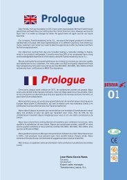
5.1 K 7.1 7.1 K<br />
(5,6 x 5,6 x 7) (7,5 x 7,5 x 12) (7,5 x 7,5 x 10)<br />
7.1 S 10.1<br />
(7,5 x 7,5 x 13) (10 x 10 x 16)<br />
Die technischen Daten spezifizieren die Bauelemente,<br />
gelten jedoch nicht als zugesicherte Garantiewerte.<br />
The technical data specify the components but they<br />
must not be understood as guaranteed values in legal<br />
sense.<br />
Für Ihre Anfrage können Sie das Formblatt auf Seite<br />
3.46 benutzen.<br />
Use the form on page 3.46 for your inquiry.<br />
3.23
3<br />
Filter / Spulen / Bausätze / Kunststoff<strong>teil</strong>e<br />
Filters / Coil Assemblies / Thermoplastic Parts<br />
Vorabgeglichene<br />
Filterspulen<br />
Reihe 5.1 K, 1 Wicklung<br />
Raster 1,80 mm<br />
Preadjusted<br />
filter coils<br />
Typ 5.1 K, 1 winding<br />
grid 1,80 mm<br />
L bei f Bereich Q bei f Anschluss an Stift Windungen Artikelnummer<br />
[µH] at [MHz] range ≥ at [MHz] connection to pin turns part number<br />
[MHz] A E<br />
start end<br />
0,022 10 100 ÷ 300 90 150 1 5 1 3 / 4 00 5298 01<br />
0,039 10 100 ÷ 300 80 150 1 5 2 3 / 4 00 5298 02<br />
0,047 10 100 ÷ 300 85 150 1 5 2 3 / 4 00 5298 03<br />
0,056 10 100 ÷ 300 75 150 1 5 3 3 / 4 00 5298 04<br />
0,082 10 100 ÷ 300 75 150 1 5 3 3 / 4 00 5298 05<br />
0,12 1 100 ÷ 300 70 100 1 5 4 3 / 4 00 5298 06<br />
0,15 1 100 ÷ 300 70 100 1 5 5 3 / 4 00 5298 07<br />
0,22 1 100 ÷ 300 70 100 1 5 6 3 / 4 00 5298 08<br />
0,27 1 100 ÷ 300 65 100 1 5 7 3 / 4 00 5298 09<br />
0,33 1 10 ÷ 200 65 70 1 5 8 3 / 4 00 5298 10<br />
0,39 1 10 ÷ 200 60 70 1 5 9 3 / 4 00 5298 11<br />
0,47 1 10 ÷ 200 60 70 1 5 10 3 / 4 00 5298 12<br />
0,56 1 10 ÷ 200 35 70 1 5 12 3 / 4 00 5298 13<br />
0,68 1 10 ÷ 200 55 50 1 5 13 3 / 4 00 5298 14<br />
0,82 1 10 ÷ 200 50 50 1 5 15 3 / 4 00 5298 15<br />
1 1 10 ÷ 200 45 50 1 5 17 3 / 4 00 5298 16<br />
1,2 1 10 ÷ 200 40 20 1 5 19 3 / 4 00 5298 17<br />
1,5 1 10 ÷ 200 40 20 1 5 21 3 / 4 00 5298 18<br />
1,8 1 10 ÷ 200 45 20 1 5 23 3 / 4 00 5298 19<br />
2,2 1 1 ÷ 15 40 10 1 5 23 3 / 4 00 5298 20<br />
2,7 1 1 ÷ 15 40 10 1 5 27 3 / 4 00 5298 21<br />
3,3 1 1 ÷ 15 40 10 1 5 31 3 / 4 00 5298 22<br />
3,9 1 1 ÷ 15 40 10 1 5 32 3 / 4 00 5298 23<br />
4,7 1 1 ÷ 15 35 10 1 5 35 3 / 4 00 5298 24<br />
5,6 1 1 ÷ 15 40 10 1 5 38 3 / 4 00 5298 25<br />
6,8 1 1 ÷ 15 35 10 1 5 44 3 / 4 00 5298 26<br />
8,2 1 1 ÷ 15 35 10 1 5 49 3 / 4 00 5298 27<br />
10 1 1 ÷ 15 30 7 1 5 52 3 / 4 00 5298 28<br />
12 1 1 ÷ 15 30 7 1 5 58 3 / 4 00 5298 29<br />
3.24<br />
Directive RoHS<br />
2002/95/EG compliant<br />
pb
3<br />
Filter / Spulen / Bausätze / Kunststoff<strong>teil</strong>e<br />
Filters / Coil Assemblies / Thermoplastic Parts<br />
Vorabgeglichene<br />
Filterspulen<br />
Reihe 7.1, 1 Wicklung<br />
Raster 2,50 mm<br />
Preadjusted<br />
filter coils<br />
Typ 7.1, 1 winding<br />
grid 2,50 mm<br />
Ansicht von der Unterseite.<br />
View from the bottom side.<br />
L bei f Bereich Q bei f Anschluss an Stift Windungen Artikelnummer<br />
[µH] at [MHz] range ≥ at [MHz] connection to pin turns part number<br />
[MHz] A E<br />
start end<br />
0,35 10 1 ÷ 15 55 10 2 1 3 3 / 4 00 5320 15<br />
0,59 10 1 ÷ 15 70 10 5 1 4 3 / 4 00 5320 18<br />
0,62 10 1 ÷ 15 70 8,4 4 2 5 3 / 4 00 5345 40<br />
0,83 10 1 ÷ 15 100 10,7 4 5 6 1 / 4 00 5166 00<br />
1 10 1 ÷ 15 85 10 5 1 6 1 / 2 00 5313 00<br />
1,13 1 1 ÷ 15 100 10 1 5 7 3 / 4 00 5908 00<br />
1,23 1 1 ÷ 15 75 5 1 5 7 3 / 4 00 5349 04<br />
1,1 1 1 ÷ 15 100 5 2 1 7 1 / 4 00 5347 38<br />
1,4 1 1 ÷ 15 110 5 1 2 8 1 / 4 00 5347 00 *1)<br />
1,51 1 1 ÷ 15 80 10 5 4 8 1 / 2 00 5929 00<br />
1,6 1 1 ÷ 15 140 4 2 4 8 1 / 4 00 5342 13<br />
1,6 1 1 ÷ 15 120 5 1 2 9 1 / 4 00 5347 39<br />
2 1 1 ÷ 15 100 8,4 4 2 9 3 / 4 00 5345 31<br />
2,2 1 1 ÷ 15 110 10 5 1 10 1 / 4 00 5313 05<br />
2,47 1 1 ÷ 15 100 5,6 4 2 10 3 / 4 00 5345 16<br />
2,5 1 1 ÷ 15 90 10 5 1 11 00 5823 00<br />
2,7 1 1 ÷ 15 110 10 5 1 11 1 / 4 00 5313 06<br />
2,4 1 1 ÷ 15 130 5 2 1 10 1 / 2 00 5347 34<br />
3 1 1 ÷ 15 120 10 5 1 11 3 / 4 00 5952 00<br />
3,14 1 1 ÷ 15 120 5 5 1 12 1 / 4 00 5349 03<br />
3,3 1 1 ÷ 15 110 10 5 1 12 1 / 4 00 5313 07<br />
3,4 1 1 ÷ 15 140 5 2 1 12 3 / 4 00 5347 32<br />
3,5 1 1 ÷ 15 175 4 2 4 12 1 / 4 00 5342 11<br />
3,6 1 1 ÷ 15 90 10,7 5 1 13 00 5814 00<br />
3,9 1 1 ÷ 15 95 5 5 1 13 1 / 2 00 5313 08<br />
4 1 1 ÷ 15 150 5 1 2 13 3 / 4 00 5347 35<br />
4 1 1 ÷ 15 120 5 5 1 13 1 / 4 00 5348 11<br />
4,52 1 1 ÷ 15 120 5 1 5 14 3 / 4 00 5349 06<br />
4,7 1 1 ÷ 15 95 5 5 1 15 1 / 4 00 5313 09<br />
4,95 1 1 ÷ 15 120 7 5 1 15 1 / 4 00 5320 23<br />
5 1 1 ÷ 15 150 5 2 1 15 3 / 4 00 5347 42<br />
5,6 1 1 ÷ 15 100 5 5 1 16 1 / 4 00 5313 10<br />
5,8 1 1 ÷ 15 110 10,7 5 2 17 1 / 4 00 5170 00<br />
6,05 1 1 ÷ 15 120 7 5 1 16 3 / 4 00 5320 19<br />
*1) Becher um 90 0 gedreht<br />
*1) Screening can 90 0 turned<br />
3.25<br />
Directive RoHS<br />
2002/95/EG compliant<br />
pb
3<br />
Filter / Spulen / Bausätze / Kunststoff<strong>teil</strong>e<br />
Filters / Coil Assemblies / Thermoplastic Parts<br />
Vorabgeglichene<br />
Filterspulen<br />
Reihe 7.1, 1 Wicklung<br />
Raster 2,50 mm<br />
Preadjusted<br />
filter coils<br />
Typ 7.1, 1 winding<br />
grid 2,50 mm<br />
Ansicht von der Unterseite.<br />
View from the bottom side.<br />
L bei f Bereich Q bei f Anschluss an Stift Windungen Artikelnummer<br />
[µH] at [MHz] range ≥ at [MHz] connection to pin turns part number<br />
[MHz] A E<br />
start end<br />
6,5 1 1 ÷ 15 100 15 5 1 17 1/4 00 5963 00<br />
6,8 1 1 ÷ 15 110 5 5 1 18 1 / 4 00 5313 11<br />
8,2 1 1 ÷ 15 110 5 5 1 20 1 / 4 00 5313 12<br />
9,4 1 1 ÷ 15 160 5 1 2 21 1 / 4 00 5347 31<br />
10 1 1 ÷ 15 95 5 5 1 22 1 / 4 00 5313 13<br />
12 0,1 1 ÷ 10 110 5 5 1 24 1 / 4 00 5313 14<br />
15 0,1 1 ÷ 10 100 5 5 1 26 1 / 4 00 5313 15<br />
18 0,1 1 ÷ 10 110 5 5 1 29 1 / 4 00 5313 16<br />
20 0,1 1 ÷ 10 100 5 5 1 30 1 / 4 00 5132 00<br />
22 0,1 0,5 ÷ 5 100 5 5 1 32 1 / 4 00 5313 17<br />
27 0,1 0,5 ÷ 5 110 2 5 1 36 1 / 4 00 5313 18<br />
33 0,1 0,5 ÷ 5 110 2 5 1 40 1 / 4 00 5313 19<br />
39 0,1 0,5 ÷ 5 110 2 5 1 43 1 / 4 00 5313 20<br />
47 0,1 0,5 ÷ 5 100 2 5 1 47 1 / 4 00 5313 21<br />
56 0,1 0,5 ÷ 5 100 2 5 1 51 1 / 4 00 5313 22<br />
68 0,1 0,5 ÷ 5 100 2 5 1 57 1 / 4 00 5313 23<br />
76 0,1 0,5 ÷ 5 145 1 4 2 51 3 / 4 00 5010 00<br />
82 0,1 0,5 ÷ 5 100 2 5 1 62 1 / 4 00 5313 24<br />
100 0,1 0,5 ÷ 5 135 1 4 2 62 3 / 4 00 5011 00<br />
120 0,1 0,5 ÷ 5 105 0,5 1 5 68 3 / 4 00 5348 01<br />
145 0,1 0,1 ÷ 2 120 0,46 5 1 75 1 / 4 00 5815 00<br />
170 0,1 0,1 ÷ 2 120 1 4 2 80 3 / 4 00 5013 00<br />
250 0,1 0,1 ÷ 2 90 1 5 4 100 00 5832 00<br />
470 0,1 0,1 ÷ 2 140 0,5 2 1 138 00 5964 00<br />
570 0,1 0,1 ÷ 2 115 0,46 4 5 150 00 5820 10<br />
670 0,1 0,1 ÷ 1 80 0,13 5 4 162 00 5331 00<br />
820 0,1 0,1 ÷ 1 110 0,5 5 1 180 00 5318 00<br />
1300 0,01 0,1 ÷ 1 75 0,114 4 5 226 00 5811 00<br />
2100 0,01 0,1 ÷ 1 65 0,1 1 5 288 00 5157 00 *1)<br />
2830 0,01 0,05 ÷ 0,5 95 0,2 5 1 336 00 5985 00 *1)<br />
3290 0,01 0,05 ÷ 0,5 80 0,2 2 4 360 00 5902 01<br />
8400 0,01 0,05 ÷ 0,5 85 0,2 5 1 650 00 5313 40<br />
*1) Raster 2,25 mm.<br />
*1) Grid 2,25 mm.<br />
3.26<br />
Directive RoHS<br />
2002/95/EG compliant<br />
pb
3<br />
Filter / Spulen / Bausätze / Kunststoff<strong>teil</strong>e<br />
Filters / Coil Assemblies / Thermoplastic Parts<br />
Vorabgeglichene<br />
Filterspulen<br />
Reihe 7.1 S, 1 Wicklung<br />
Raster 2,25 mm<br />
Preadjusted<br />
filter coils<br />
Typ 7.1 S, 1 winding<br />
grid 2,25 mm<br />
Ansicht von der Unterseite.<br />
View from the bottom side.<br />
L bei f Bereich Q bei f Anschluss an Stift … Windungen Artikelnummer<br />
[µH] at [MHz] range ≥ at [MHz] connection to pin … turns part number<br />
[MHz] A E<br />
start end<br />
0,016 max. 10 100 ÷ 300 100 120 1 5 1 1 / 4 00 5243 00<br />
0,036 max. 10 100 ÷ 300 100 120 1 5 2 1 / 4 00 5034 10<br />
0,046 10 50 ÷ 200 100 100 3 5 3 1 / 2 00 5334 05<br />
0,068 10 50 ÷ 200 100 150 1 5 3 1 / 4 00 5033 10<br />
0,1 min. 10 50 ÷ 200 100 100 5 1 5 1 / 4 00 5231 11<br />
0,115 10 50 ÷ 200 90 130 1 5 4 1 / 4 00 5061 00<br />
0,14 10 50 ÷ 200 80 100 5 1 5 1 / 4 00 5269 00<br />
0,135 min. 10 50 ÷ 200 100 100 5 1 6 1 / 4 00 5231 03<br />
0,2 min. 10 50 ÷ 200 90 100 1 5 7 1 / 4 00 5231 08 *1)<br />
0,33 max. 10 5 ÷ 50 80 40 2 4 7 1 / 4 00 5049 00<br />
0,4 10 5 ÷ 50 50 40 5 1 13 1 / 4 00 5285 01<br />
0,48 10 5 ÷ 50 70 50 2 4 9 1 / 4 00 5076 00<br />
0,58 max. 10 5 ÷ 50 75 40 5 4 9 3 / 4 00 5036 00<br />
0,67 min. 10 5 ÷ 50 65 40 2 4 12 1 / 2 00 5262 00<br />
0,68 10 5 ÷ 50 65 40 1 2 15 1 / 4 00 5334 00<br />
0,85 max. 10 5 ÷ 50 65 40 5 1 12 3 / 4 00 5098 00<br />
0,9 max. 10 5 ÷ 50 70 40 2 1 13 3 / 4 00 5046 00<br />
1 max. 10 5 ÷ 50 60 40 5 4 14 3 / 4 00 5048 00<br />
1,13 1 5 ÷ 50 65 40 2 5 19 1 / 2 00 5334 04 *1)<br />
1,25 max. 1 5 ÷ 50 75 40 5 4 12 3 / 4 00 5022 00 *2)<br />
1,55 min. 1 1 ÷ 15 25 10 5 1 15 1 / 4 00 5211 00<br />
2 1 3 ÷ 30 45 20 4 5 17 3 / 4 00 5224 00<br />
2,5 1 3 ÷ 30 40 20 5 1 22 1 / 4 00 5259 00<br />
3,14 1 1 ÷ 15 90 5 5 1 17 1 / 4 00 5283 03<br />
3,3 1 1 ÷ 15 45 10 5 1 32 1 / 4 00 5044 00<br />
4 1 3 ÷ 30 35 20 1 5 20 3 / 4 00 5056 00<br />
4,4 1 1 ÷ 15 20 10 5 4 22 3 / 4 00 5219 00<br />
5 1 1 ÷ 15 40 10 1 5 30 3 / 4 00 5251 10<br />
6 1 1 ÷ 15 35 10 1 5 26 1 / 4 00 5220 00<br />
8 1 0,5 ÷ 5 65 1,2 2 4 33 1 / 4 00 5800 00<br />
10 min. 0,1 1 ÷ 15 35 9 2 1 36 1 / 4 00 5255 01<br />
14 0,1 0,5 ÷ 5 75 1,2 2 4 42 1 / 4 00 5896 00<br />
18,6 0,1 0,5 ÷ 5 80 1,2 2 4 48 1 / 4 00 5831 03<br />
20 0,1 1 ÷ 15 65 5 1 4 43 1 / 2 00 5287 00<br />
23 0,1 0,5 ÷ 5 80 1,2 2 4 55 1 / 4 00 5089 00<br />
30 0,1 1 ÷ 15 65 3 5 2 55 1 / 2 00 5287 20<br />
45 0,1 1 ÷ 15 65 2 5 2 70 1 / 2 00 5287 10<br />
68 0,1 0,5 ÷ 5 40 0,5 5 1 72 1 / 4 00 5255 30<br />
120 0,1 0,1 ÷ 2 50 0,5 5 1 92 1 / 4 00 5236 00 *3)<br />
1000 0,1 0,1 ÷ 2 40 0,27 5 4 296 00 5227 00<br />
*1) Becher um 90° gedreht. *2) ohne Abschirmbecher. *3) Raster 2.5 mm.<br />
*1) Screening can 90° turned. *2) without screening can. *3) grid 2,5 mm.<br />
3.27<br />
Directive RoHS<br />
2002/95/EG compliant<br />
pb
3<br />
Filter / Spulen / Bausätze / Kunststoff<strong>teil</strong>e<br />
Filters / Coil Assemblies / Thermoplastic Parts<br />
Vorabgeglichene<br />
Filterspulen<br />
Reihe 7.1 K, 1 Wicklung<br />
Raster 2,25 mm<br />
Preadjusted<br />
filter coils<br />
Typ 7.1 K, 1 winding<br />
grid 2,25 mm<br />
Ansicht von der Unterseite.<br />
View from the bottom side.<br />
L bei f Bereich Q bei f Anschluss an Stift … Windungen Artikelnummer<br />
[µH] at [MHz] range ≥ at [MHz] connection to pin … turns part number<br />
[MHz] A E<br />
start end<br />
0,06 10 50 ÷ 200 100 100 5 1 3 3 / 4 00 5270 00<br />
0,14 10 50 ÷ 200 100 100 1 5 6 1 / 4 00 5231 05<br />
0,18 10 50 ÷ 200 100 100 5 1 7 1 / 4 00 5231 04<br />
0,315 10 50 ÷ 200 85 50 5 1 8 1 / 4 00 5285 52<br />
0,57 10 10 ÷ 100 75 60 5 2 12 1 / 2 00 5277 02<br />
0,98 10 10 ÷ 100 60 40 2 4 15 1 / 4 00 5281 42<br />
1,14 1 5 ÷ 50 60 20 5 1 16 1 / 4 00 5285 53<br />
1,34 1 5 ÷ 50 50 20 2 4 20 1 / 4 00 5250 19<br />
1,5 1 5 ÷ 50 35 20 5 1 13 1 / 4 00 5252 00 *)<br />
1,6 1 5 ÷ 50 60 40 1 5 16 3 / 4 00 5280 10<br />
1,9 1 5 ÷ 50 40 20 5 1 16 3 / 4 00 5252 30<br />
2 1 5 ÷ 50 40 20 5 1 17 1 / 4 00 5085 00<br />
3,4 1 1 ÷ 15 40 10 5 1 25 1 / 4 00 5285 23<br />
3,55 1 1 ÷ 30 55 25 2 4 30 1 / 4 00 5281 41<br />
4,3 1 1 ÷ 30 50 10 2 4 40 00 5253 24<br />
4,7 1 1 ÷ 30 45 20 5 1 30 1 / 4 00 5285 20<br />
5,1 1 1 ÷ 15 45 5 5 1 30 1 / 4 00 5285 51<br />
5,5 1 1 ÷ 15 20 10 5 1 26 1 / 4 00 5280 11<br />
7,5 1 1 ÷ 15 55 10 5 1 42 1 / 4 00 5281 30<br />
8,5 1 1 ÷ 15 40 5 2 4 55 00 5253 33<br />
68 0,1 0,5 ÷ 5 30 0,5 5 1 88 1 / 4 00 5252 10<br />
390 0,1 0,5 ÷ 5 35 0,5 5 1 188 00 5246 10<br />
*) Durchmesser der Stifte ≤ 1,5 mm.<br />
*) Diameter of pins ≤ 1,5 mm.<br />
3.28<br />
Directive RoHS<br />
2002/95/EG compliant<br />
pb
3<br />
Filter / Spulen / Bausätze / Kunststoff<strong>teil</strong>e<br />
Filters / Coil Assemblies / Thermoplastic Parts<br />
Vorabgeglichene<br />
Filterspulen<br />
Reihe 7.1, 7.1 S,<br />
1 Wicklung mit<br />
1 Anzapfung<br />
Preadjusted<br />
filter coils<br />
Typ 7.1, 7.1 S,<br />
1 winding with<br />
1 tap<br />
Ansicht von der Unterseite.<br />
View from the bottom side.<br />
L bei f Bereich Q bei f Raster Anschluss an Stift … Anzapf Windungs- Windungs- Artikelnummer<br />
[µH] at [MHz] range ≥ at [MHz] grid connection to pin … tap zahl zahl bis Anzapf part number<br />
[MHz] [mm] A E turns turns<br />
start end start - tap<br />
Reihe 7.1 type 7.1<br />
0,83 10 1 ÷ 15 85 10,7 2,5 4 5 3 6 1 / 4 2 1 / 2 00 5167 00<br />
0,975 10 1 ÷ 15 90 10,7 2,5 5 1 3 7 1 / 4<br />
3 /4 00 5303 00<br />
4 1 1 ÷ 15 80 10 2,5 5 1 3 15 3 / 4 2 00 5314 00<br />
4,45 1 1 ÷ 15 90 10,7 2,25 2 5 3 14 1 / 2 7 00 5894 00<br />
8,05 0,1 1 ÷ 15 100 8,4 2,5 4 2 3 19 1 / 2 9 3 / 4 00 5345 42<br />
11,68 0,1 1 ÷ 15 100 5,6 2,5 4 2 3 22 11 00 5345 20 *2)<br />
16,7 0,1 1 ÷ 15 80 5,4 2,5 4 2 3 28 14 00 5345 44 *2)<br />
19,6 0,1 1 ÷ 15 70 5,4 2,5 4 2 3 30 15 00 5345 43 *2)<br />
23,6 0,1 1 ÷ 15 80 5,4 2,5 4 2 3 33 1 / 2 16 3 / 4 00 5345 48 *2)<br />
27,81 0,1 1 ÷ 15 65 5,6 2,5 4 2 3 36 18 00 5345 21 *2)<br />
32 0,1 0,5 ÷ 5 55 2 2,5 1 5 3 36 1 / 2 18 00 5342 08<br />
68 0,1 0,5 ÷ 5 110 2 2,25 2 4 1 60 1 / 4 29 3 / 4 00 5324 00 *1)<br />
68 0,1 0,5 ÷ 5 110 2 2,25 2 4 1 60 1 / 4 32 3 / 4 00 5324 01 *1)<br />
82 0,1 0,5 ÷ 5 100 0,46 2,5 5 1 3 57 20 1 / 2 00 5960 00<br />
92 0,1 0,5 ÷ 5 85 2 2,25 4 2 3 65 1 / 2 32 3 / 4 00 5332 00<br />
403 0,1 0,1 ÷ 2 65 0,13 2,25 2 4 3 132 48 00 5327 13<br />
509 0,1 0,1 ÷ 2 60 0,11 2,25 2 4 3 142 54 00 5327 12<br />
626 0,1 0,1 ÷ 2 55 0,09 2,25 2 4 3 162 59 00 5327 11<br />
735 0,1 0,1 ÷ 2 105 0,46 2,5 4 2 3 172 85 00 5970 00<br />
760 0,1 0,1 ÷ 2 50 0,07 2,25 2 4 3 172 65 00 5327 14<br />
Reihe 7.1 S<br />
type 7.1 S<br />
0,069 10 50 ÷ 200 60 100 2,5 1 5 2 3 1 / 4 1 3 / 4 00 5285 36<br />
0,079 10 50 ÷ 200 70 100 2,5 1 5 2 3 1 / 4<br />
3 /4 00 5285 35<br />
0,09 10 50 ÷ 200 100 100 2,25 1 4 2 5 1 / 2 4 1 / 4 00 5334 07<br />
0,12 10 50 ÷ 200 65 100 2,25 4 5 3 3 3 / 4 1 1 / 4 00 5042 00<br />
0,133 10 50 ÷ 200 75 100 2,25 5 2 4 4 1 / 2 1 3 / 4 00 5063 00<br />
0,14 10 50 ÷ 200 80 100 2,5 5 1 4 5 3 / 4 2 1 / 4 00 5285 37<br />
0,56 10 10 ÷ 100 70 40 2,5 2 4 5 15 1 / 2 7 1 / 2 00 5276 10<br />
0,7 10 10 ÷ 100 60 40 2,25 5 3 4 13 4 00 5907 01<br />
1,36 1 5 ÷ 50 35 10 2,5 1 5 3 12 4 1 / 2 00 5285 17<br />
1,66 1 5 ÷ 50 40 10 2,5 1 5 3 12 4 1 / 2 00 5285 18<br />
3,9 1 1 ÷ 30 50 10,7 2,25 2 1 4 27 3 / 4 17 1 / 4 00 5026 00<br />
*1) Becher um 90 0 gedreht. *2) Bifilar gewickelt.<br />
*1) Screening can 90 0 turned. *2) Wound bifilar.<br />
3.29<br />
Directive RoHS<br />
2002/95/EG compliant<br />
pb
3<br />
Filter / Spulen / Bausätze / Kunststoff<strong>teil</strong>e<br />
Filters / Coil Assemblies / Thermoplastic Parts<br />
Vorabgeglichene<br />
Filterspulen<br />
Reihe 7.1 K,<br />
1 Wicklung mit<br />
1 Anzapfung<br />
Raster 2,25 mm<br />
Ansicht von der Unterseite.<br />
View from the bottom side.<br />
Preadjusted<br />
filter coils<br />
Typ 7.1 K,<br />
1 winding with<br />
1 tap<br />
grid 2,25 mm<br />
L bei f Bereich Q bei f Anschluss an Stift … Anzapf Windungs- Windungs- Artikelnummer<br />
[µH] at [MHz] range ≥ at [MHz] connection to pin … tap zahl zahl bis Anzapf part number<br />
[MHz] A E turns turns<br />
start end start - tap<br />
0,077 10 50 ÷ 200 90 100 4 2 1 4 1 / 4 2 1 / 2 00 5289 00<br />
0,156 10 50 ÷ 200 90 100 4 1 5 5 1 / 2 1 3 / 4 00 5285 46<br />
0,229 10 50 ÷ 200 75 100 4 2 1 8 1 / 4 4 1 / 2 00 5289 01<br />
1,6 1 1 ÷ 30 55 20 2 4 3 20 1 / 4 7 00 5250 40<br />
1,6 1 1 ÷ 30 55 40 2 4 3 20 12 00 5281 11<br />
1,6 1 1 ÷ 30 55 40 2 4 3 20 17 00 5281 13<br />
1,66 1 1 ÷ 30 50 20 2 1 3 18 1 / 2 13 00 5288 20<br />
1,7 1 1 ÷ 30 55 20 2 4 1 21 1 / 4 9 3 / 4 00 5250 04<br />
1,96 1 1 ÷ 30 50 13 4 5 3 19 1 / 2 6 1 / 2 00 5288 60<br />
4,7 1 1 ÷ 15 35 10,7 2 3 1 28 15 1 / 2 00 5288 50<br />
5,3 1 1 ÷ 15 45 7 4 2 1 37 1 / 2 16 1 / 2 00 5250 01<br />
5,3 1 1 ÷ 15 45 7 4 2 1 37 1 / 2 16 1 / 2 00 5250 11<br />
5,4 1 1 ÷ 15 20 10 5 3 4 28 1 / 2 17 00 5286 20<br />
7 1 1 ÷ 15 20 10 1 2 3 32 19 00 5286 10<br />
9,3 1 1 ÷ 15 50 7 2 4 1 50 1 / 4 27 3 / 4 00 5250 00<br />
3.30<br />
Directive RoHS<br />
2002/95/EG compliant<br />
pb
3<br />
Filter / Spulen / Bausätze / Kunststoff<strong>teil</strong>e<br />
Filters / Coil Assemblies / Thermoplastic Parts<br />
Vorabgeglichene<br />
Filterspulen<br />
Reihe 7.1, 2 Wicklungen<br />
Preadjusted<br />
filter coils<br />
Typ 7.1, 2 windings<br />
Ansicht von der Unterseite.<br />
View from the bottom side.<br />
L bei f Bereich Q bei f Raster Anschluss d. Wicklung an Stift Windungszahl Artikelnummer<br />
[µH] at [MHz] range ≥ at [MHz] grid connection of winding to pin der Wicklung part number<br />
[MHz] [mm] 1 2 turns winding<br />
A E A E 1 2<br />
start end start end<br />
0,37 10 1 ÷ 15 60 10,7 2,5 5 1 2 4 4 1 /4 00 5940 00<br />
1,8 1 1 ÷ 15 70 5,5 2,25 4 2 1 5 9 2 3 / 4 00 5150 00<br />
2,1 1 1 ÷ 15 110 10,7 2,5 1 5 4 2 9 1 / 2 2 1 / 2 00 5883 00<br />
2,2 1 1 ÷ 15 80 10,7 2,5 2 4 5 1 10 1 / 4 4 1 / 4 00 5163 00<br />
2,5 1 0,5 ÷ 5 55 5 2,5 4 2 5 1 10 10 00 5015 00<br />
2,7 1 1 ÷ 15 70 10,7 2,5 2 3 1 5 11 3 00 5856 00<br />
4,37 1 1 ÷ 15 70 10,7 2,5 5 1 4 2 14 1 / 4 2 00 5810 00<br />
7 1 1 ÷ 15 70 10,7 2,5 2 4 5 1 18 1 / 4 2 3 / 4 00 5920 00<br />
8,7 1 1 ÷ 15 80 9,4 2,5 5 1 2 4 20 1 / 4 3 1 / 4 00 5897 00<br />
10 1 1 ÷ 15 80 10 2,5 5 4 1 2 21 1 / 2 5 00 5830 00<br />
25,6 0,1 0,5 ÷ 5 95 0,46 2,25 2 4 5 1 31 1 / 4 24 1 / 4 00 5183 00<br />
42 0,1 0,5 ÷ 5 80 1 2,5 1 5 2 4 42 3 / 4 10 1 / 4 00 5193 00<br />
68 0,1 0,5 ÷ 5 100 0,46 2,5 5 1 2 4 51 1 / 4 5 1 / 4 00 5961 00<br />
124 0,1 0,5 ÷ 5 112 0,46 2,5 2 1 4 3 70 30 00 5928 00<br />
146 0,1 0,5 ÷ 5 125 0,46 2,25 2 4 5 1 76 1 / 4 4 00 5877 00<br />
148 0,1 0,5 ÷ 5 100 0,46 2,5 5 1 2 3 76 1 / 4 38 1 / 4 00 5836 00<br />
182 0,1 0,5 ÷ 5 120 0,46 2,5 4 2 1 5 84 3 / 4 14 3 / 4 00 5191 00<br />
250 0,1 0,5 ÷ 5 90 0,5 2,5 5 2 4 1 100 1 / 2 18 1 / 2 00 5344 00<br />
302 0,1 0,5 ÷ 5 120 0,5 2,5 5 1 2 4 109 1 / 4 4 1 / 4 00 5954 01<br />
326 0,1 0,5 ÷ 5 120 0,8 2,5 4 5 1 2 113 20 00 5909 00<br />
360 0,1 0,5 ÷ 5 132 0,46 2,5 1 5 4 2 119 3 / 4 11 1 / 4 00 5923 00<br />
403 0,1 0,1 ÷ 1 60 0,13 2,25 2 4 5 1 126 1 / 4 42 1 / 4 00 5327 03<br />
403 0,1 0,1 ÷ 1 60 0,13 2,25 2 4 5 1 126 1 / 4 12 1 / 4 00 5327 07<br />
472 0,1 0,1 ÷ 1 140 0,5 2,5 1 5 3 2 137 1 / 4 14 3 / 4 00 5965 10<br />
509 0,1 0,1 ÷ 1 55 0,11 2,25 2 4 5 1 142 1 / 4 47 1 / 4 00 5327 02<br />
509 0,1 0,1 ÷ 1 55 0,11 2,25 2 4 5 1 142 1 / 4 14 1 / 4 00 5327 06<br />
510 0,1 0,05 ÷ 1 140 0,5 2,5 1 5 3 2 142 3 / 4 14 3 / 4 00 5965 00<br />
555 0,1 0,05 ÷ 1 85 0,46 2,5 5 1 2 3 148 1 / 4 74 1 / 4 00 5835 00<br />
626 0,1 0,05 ÷ 1 50 0,09 2,25 2 4 5 1 157 1 / 4 52 1 / 4 00 5327 01<br />
626 0,1 0,05 ÷ 1 50 0,09 2,25 2 4 5 1 157 1 / 4 15 1 / 4 00 5327 05<br />
650 0,1 0,05 ÷ 1 125 0,47 2,5 3 2 5 4 160 1 / 2 10 1 / 2 00 5821 00<br />
760 0,1 0,05 ÷ 1 45 0,07 2,25 2 4 5 1 173 1 / 4 58 1 / 4 00 5327 04<br />
760 0,1 0,05 ÷ 1 45 0,07 2,25 2 4 5 1 173 1 / 4 16 1 / 4 00 5327 08<br />
800 0,1 0,05 ÷ 1 60 0,2 2,5 2 3 1 5 171 53 3 / 4 00 5335 00<br />
1000 0,1 0,05 ÷ 1 60 0,12 2,5 1 5 4 2 199 3 / 4 69 3 / 4 00 5329 10<br />
2500 0,01 0,05 ÷ 1 80 0,3 2,25 2 4 1 5 315 1 / 4 74 3 / 4 00 5949 10<br />
2500 0,01 0,05 ÷ 1 80 0,3 2,25 2 4 5 1 315 1 / 4 57 1 / 4 00 5949 20<br />
3700 0,01 0,05 ÷ 1 65 0,2 2,5 4 2 5 1 389 3 / 4 6 1 / 4 00 5326 00<br />
3.31<br />
Directive RoHS<br />
2002/95/EG compliant<br />
pb
3<br />
Filter / Spulen / Bausätze / Kunststoff<strong>teil</strong>e<br />
Filters / Coil Assemblies / Thermoplastic Parts<br />
Vorabgeglichene<br />
Filterspulen<br />
Reihe 7.1 S, 2 Wicklungen<br />
Preadjusted<br />
filter coils<br />
Typ 7.1 S, 2 windings<br />
Ansicht von der Unterseite.<br />
View from the bottom side.<br />
L bei f Bereich Q bei f Raster Anschluss d. Wicklung an Stift Windungszahl Artikelnummer<br />
[µH] at [MHz] range ≥ at [MHz] grid connection of winding to pin der Wicklung … part number<br />
[MHz] [mm] 1 2 turns winding …<br />
A E A E 1 2<br />
start end start end<br />
0,023 10 50 ÷ 200 90 200 2,5 4 2 1 5 1 3 / 4 1 3 / 4 00 5261 10<br />
0,041 10 50 ÷ 200 110 100 2,25 5 1 3 2 3 1 / 4 1 1 / 4 00 5274 15<br />
0,079 10 50 ÷ 200 60 100 2,5 1 5 2 4 4 1 / 2 4 1 / 2 00 5346 00 *)<br />
0,087 10 50 ÷ 200 90 100 2,25 4 2 1 5 5 1 / 4 1 1 / 4 00 5334 01<br />
0,09 10 50 ÷ 200 60 130 2,5 4 2 1 5 4 1 / 4 4 1 / 4 00 5261 02<br />
0,123 10 50 ÷ 200 90 100 2,25 1 5 4 2 5 1 / 4 3 1 / 4 00 5269 10<br />
0,223 10 50 ÷ 200 85 100 2,25 2 4 5 1 7 3 / 4 4 3 / 4 00 5231 09<br />
0,275 10 1 ÷ 15 18 10 2,25 4 1 5 2 5 1 / 2 5 1 / 2 00 5287 40<br />
0,375 10 5 ÷ 50 70 40 2,25 2 4 5 1 7 1 / 4 1 1 / 4 00 5049 20<br />
0,54 10 1 ÷ 15 35 10 2,25 2 3 5 1 15 1 / 4 1 1 / 4 00 5257 01 *)<br />
0,95 10 5 ÷ 50 50 40 2,5 2 4 1 5 16 1 / 4 1 3 / 4 00 5279 03<br />
1 1 5 ÷ 50 45 40 2,5 4 2 1 5 12 3 / 4 4 3 / 4 00 5238 00<br />
1 1 5 ÷ 50 45 40 2,5 4 2 1 5 15 1 / 4 5 1 / 4 00 5259 15<br />
1 1 1 ÷ 15 32 10 2,25 2 3 5 1 24 1 / 4 1 1 / 4 00 5257 00 *)<br />
2 1 1 ÷ 15 30 10 2,25 2 3 5 1 30 1 / 4 1 1 / 4 00 5257 02 *)<br />
2 1 5 ÷ 50 35 40 2,5 4 2 1 5 20 1 / 4 10 1 / 4 00 5259 22<br />
3 1 1 ÷ 15 55 10 2,25 2 4 5 1 27 1 / 4 2 1 / 4 00 5853 10<br />
62 0,1 0,1 ÷ 1 30 0,29 2,25 5 4 3 1 68 3 / 4 34 3 / 4 00 5226 00<br />
180 0,1 0,1 ÷ 1 35 0,5 2,25 5 1 4 2 120 1 / 4 30 3 / 4 00 5233 01<br />
180 0,1 0,1 ÷ 1 40 0,5 2,25 5 1 4 2 120 1 / 4 12 3 / 4 00 5233 02<br />
*) ohne Gewindekern.<br />
*) without screw core.<br />
3.32<br />
Directive RoHS<br />
2002/95/EG compliant<br />
pb
3<br />
Filter / Spulen / Bausätze / Kunststoff<strong>teil</strong>e<br />
Filters / Coil Assemblies / Thermoplastic Parts<br />
Vorabgeglichene<br />
Filterspulen<br />
Reihe 7.1 K, 2 Wicklungen<br />
Raster 2,25 mm<br />
Preadjusted<br />
filter coils<br />
Typ 7.1 K, 2 windings<br />
grid 2,25 mm<br />
Ansicht von der Unterseite.<br />
View from the bottom side.<br />
L bei f Bereich Q bei f Anschluss d. Wicklung an Stift Windungszahl Artikelnummer<br />
[µH] at [MHz] range ≥ at [MHz] connection of winding to pin der Wicklung … part number<br />
[MHz] 1 2 turns winding …<br />
A E A E 1 2<br />
start end start end<br />
0,055 10 50 ÷ 200 75 100 2 4 5 1 3 1 / 4 2 1 / 4 00 5231 07<br />
0,1 10 50 ÷ 200 90 100 2 4 5 1 5 1 / 4 3 1 / 4 00 5231 06<br />
0,33 10 50 ÷ 200 80 50 2 4 5 1 8 1 / 4<br />
1 /4 00 5285 43<br />
0,43 10 5 ÷ 50 50 40 5 3 1 2 10 7 00 5281 15<br />
0,55 10 50 ÷ 200 55 50 5 1 2 4 10 1 / 4 2 1 / 4 00 5285 40<br />
0,8 10 5 ÷ 50 50 40 4 2 1 5 12 1 / 4 1 1 / 4 00 5086 10<br />
1,35 1 1 ÷ 30 30 10 2 3 5 1 24 1 / 4 1 1 / 4 00 5270 05<br />
1,55 1 5 ÷ 50 40 40 5 3 1 2 20 12 00 5281 16<br />
2 1 5 ÷ 50 30 21 5 1 2 4 17 1 / 4 4 1 / 4 00 5086 00<br />
275 0,1 0,5 ÷ 5 45 0,5 4 2 5 1 160 16 1 / 4 00 5086 20<br />
3.33<br />
Directive RoHS<br />
2002/95/EG compliant<br />
pb
3<br />
Filter / Spulen / Bausätze / Kunststoff<strong>teil</strong>e<br />
Filters / Coil Assemblies / Thermoplastic Parts<br />
Vorabgeglichene<br />
Filterspulen<br />
Reihe 7.1, 7.1 K<br />
Wicklung mit Anzapfung,<br />
symmetrisch aufgebaut<br />
Preadjusted filter<br />
coils<br />
Typ 7.1, 7.1 K<br />
1 winding with 1 tap,<br />
symmetrical configuration<br />
Ansicht von der Unterseite.<br />
View from the bottom side.<br />
Bereich Anschluss an Stift Anzapf Windungs Artikelnummer<br />
L bei f range Q bei f Raster connection to pin -zahl part number<br />
[µH] at [MHz] [MHz] ≥ at [MHz] grid tap turns<br />
A<br />
E<br />
[mm] start end<br />
Reihe 7.1 type 7.1<br />
2,4 1 1 ÷ 15 80 10 2,5 5 1 3 2 x 5 1 / 2 00 5139 00<br />
8,05 1 1 ÷ 15 100 8,4 2,5 4 2 3 2 x 9 3 / 4 00 5345 42<br />
19,6 0,1 1 ÷ 15 85 5,4 2,5 4 2 3 2 x 15 00 5345 43<br />
23,6 0,1 1 ÷ 15 120 2,5 2,5 4 2 3 2 x 16 3 / 4 00 5345 48<br />
27 0,1 0,5 ÷ 5 110 1 2,5 2 4 3 2 x 17 1 / 4 00 5348 18<br />
30 0,1 0,5 ÷ 5 100 2 2,5 4 2 3 00 5345 07<br />
Reihe 7.1 K<br />
type 7.1 K<br />
0,53 10 5 ÷ 50 45 40 2,25 2 4 3 2 x 5 00 5266 23<br />
0,5 10 5 ÷ 50 55 40 2,25 2 4 3 2 x 6 00 5266 21<br />
0,77 10 3 ÷ 30 50 20 2,25 4 5 3 2 x 6 00 5288 10*1)<br />
1,8 1 3 ÷ 30 45 20 2,25 4 2 3 2 x 11 00 5266 10*2)<br />
*1) ohne Abschirmbecher. *2) Abschirmbecher um 90° gedreht.<br />
*1) without screening can. *2) screening can 90° turned.<br />
3.34<br />
Directive RoHS<br />
2002/95/EG compliant<br />
pb
3<br />
Filter / Spulen / Bausätze / Kunststoff<strong>teil</strong>e<br />
Filters / Coil Assemblies / Thermoplastic Parts<br />
Vorabgeglichene<br />
Filterspulen<br />
Reihe 7, 2 Wicklungen,<br />
1 Wicklung angezapft<br />
Preadjusted filter<br />
coils<br />
Typ 7, 2 windings,<br />
1 winding tapped<br />
Ansicht von der Unterseite.<br />
View from the bottom side.<br />
Bereich Anschl. d. Wicklung an Stift Anzapf Windungszahl Windungsz. Art.-Nr.<br />
L bei f range Q bei f connection of winding to pin an Stift der Wicklung bis Anzapf part number<br />
[µH] at [MHz] [MHz] ≥ at [MHz] 1 2 tap to turns winding turns to tap<br />
A E A E pin 1 2<br />
Reihe 7.1 start end start type end 7.1<br />
0,83 10 1 ÷ 15 70 10,7 4 5 1 2 3 6 1 / 4 1 1 / 2 2 1 / 2 00 5168 00<br />
0,94 10 1 ÷ 15 70 10 4 2 1 5 3 6 3 / 4<br />
3 /4 3 3 / 4 00 5137 00<br />
1,9 1 1 ÷ 15 80 10 1 3 5 4 2 9 1 / 2<br />
3 /4 5 00 5905 00<br />
2,5 1 1 ÷ 15 65 10,7 4 3 5 1 2 10 3 / 4 4 1 / 4 7 3 / 4 00 5165 00<br />
2,6 1 1 ÷ 15 70 10 5 1 4 2 3 11 4 3 / 4 5 1 / 2 00 5138 00<br />
2,8 1 1 ÷ 15 100 10 4 3 2 1 5 11 3 / 4<br />
3 /4 9 3 / 4 00 5914 00<br />
3,2 1 1 ÷ 15 80 10,7 4 2 1 5 2 12 1 3 / 4 6 00 5164 00<br />
5,13 1 1 ÷ 15 75 7 1 5 4 2 3 15 3 / 4 10 5*1) 00 5348 06<br />
5,15 1 1 ÷ 15 75 10,7 2 4 1 5 3 14 1 / 2<br />
3 /4 7 1 / 4 00 5956 00<br />
8,3 *2) 1 1 ÷ 15 65 7 2 4 5 1 3 26 1 1 / 4 6 00 5348 05<br />
15 0,1 0,5 ÷ 5 100 2 4 2 5 1 3 24 5 12 00 5016 00<br />
18 0,1 0,5 ÷ 5 45 0,5 2 4 5 1 3 27 43 1 / 4 13 1 / 2 005027 10<br />
68 0,1 0,5 ÷ 5 95 0,46 2 4 1 5 3 52 6 3 / 4 26 00 5307 00<br />
75 0,1 0,1 ÷ 3 70 1 4 2 1 5 3 57 1 / 2 6 1 / 4 28 3 / 4 00 5192 00<br />
82 0,1 0,1 ÷ 3 100 0,46 4 3 5 1 2 56 3 / 4 18 3 / 4 16 3 / 4 00 5135 00<br />
120 *) 0,1 0,1 ÷ 3 70 0,46 3 4 1 5 2 88 1 / 2 2 1 / 4 44 00 5319 01*)<br />
125 0,1 0,1 ÷ 3 80 0,46 4 2 1 5 3 70 1 / 4 35 1 / 4 35 1 / 4 00 5341 00<br />
225 0,1 0,1 ÷ 3 110 1 2 4 1 5 3 94 1 / 2 24 1 / 2 88 00 5112 00<br />
340 0,1 0,1 ÷ 3 115 0,46 3 4 5 1 2 121 4 1 / 2 116 00 5911 00<br />
375 0,1 0,1 ÷ 3 115 0,46 3 2 1 5 4 121 4 1 / 2 101 005881 00<br />
375 0,1 0,1 ÷ 3 115 0,46 3 2 1 5 4 121 4 3 / 4 88 00 5910 00<br />
670 0,1 0,1 ÷ 3 100 0,5 4 2 1 5 3 163 1 / 2 64 3 / 4 53 3 / 4 00 5333 02<br />
775 0,1 0,1 ÷ 3 80 0,46 4 2 5 1 3 175 3 / 4 8 30 00 5943 00<br />
1820 0,01 0,05 ÷ 0,5 60 0,12 4 1 3 2 5 269 10 70 1 / 4 00 5329 00<br />
1900 0,01 0,05 ÷ 0,5 85 0,2 2 4 1 5 3 264 53 3 / 4 171 00 5868 00<br />
Reihe 7.1 S<br />
type 7.1 S<br />
0,03*) 10 50 ÷ 200 85 150 2 4 1 5 3 1 1 / 2 2 1 / 2<br />
3 /4 00 5276 00*)<br />
0,067 10 50 ÷ 200 55 150 4 2 5 1 3 2 1 / 2<br />
3 /4 1 1 / 4 00 5259 20<br />
0,14 10 50 ÷ 200 45 100 4 2 1 5 3 4 1 / 2 5 1 / 4 2 1 / 4 00 5259 17<br />
0,25 10 50 ÷ 200 40 100 4 2 1 5 3 6 1 / 2 4 1 / 4 3 1 / 4 00 5259 19<br />
0,52 10 10 ÷ 100 45 40 4 2 1 5 3 10 1 / 2 7 1 / 4 5 1 / 4 00 5259 16<br />
0,71 10 10 ÷ 100 45 40 4 2 1 5 3 12 1 / 2 6 1 / 4 6 1 / 4 00 5259 13<br />
1,17 1 10 ÷ 100 40 40 4 2 1 5 3 16 1 / 2 8 1 / 4 8 1 / 4 00 5259 14<br />
1,4 1 5 ÷ 50 30 40 4 2 1 5 3 16 1 / 2 18 1 / 4 8 1 / 2 00 5259 21<br />
*) Raster 2,25 mm. *1) Z an n2. *2) an Stift 3 und 4.<br />
*) grid 2,25 mm. *1) tap at n2. *2) between pin 3 and pin 4.<br />
3.35<br />
Directive RoHS<br />
2002/95/EG compliant<br />
pb
3<br />
Filter / Spulen / Bausätze / Kunststoff<strong>teil</strong>e<br />
Filters / Coil Assemblies / Thermoplastic Parts<br />
Vorabgeglichene Filterspulen<br />
Reihe 7.1 E, 1 Wicklung<br />
Preadjusted filter coils<br />
Type 7.1 E, 1 winding<br />
Aufbau und Abmessungen:<br />
Design and dimensions:<br />
Pos. Bezeichnung Werkstoff<br />
Item Name Material<br />
1 Becher Cu-Ag<br />
can<br />
2 Gewindekern Ms / Ferrit<br />
screw core<br />
brass / ferrite<br />
3 Spulenrohr Noryl (PPE)<br />
former<br />
4 Wendel Cu-AG<br />
helix<br />
5 Rahmenhälfte Noryl (PPO)<br />
yoke halves<br />
Ansicht von der Unterseite.<br />
View from the bottom side.<br />
Eigenschaften:<br />
Lötbarkeit nach DIN IEC 68-2-20 Ta:<br />
235°C, 5 Sek.<br />
Lötwärmebeständigkeit -2-20 Tb:<br />
260°C 5 Sek.<br />
Auszugsfestigkeit der Stifte: 5 N<br />
Zulässige Betriebstemperatur:<br />
- 40°C bis +125°C<br />
Temperaturkoeffizient von -25°C bis +85°C:<br />
ca. ± 50 x 10 -6 / K<br />
ca. 100 ± 75 x 10 -6 / K (F 100b)<br />
Characteristic properties:<br />
Solderability as per DIN IEC 68-2-20 Ta:<br />
235° C 5 sec.<br />
Resistance soldering heat -2-20 Tb:<br />
260° C 5 sec.<br />
Pulling strength of the pins: 5 N<br />
Permissible working temperature:<br />
- 40°C to + 125°C<br />
Temperature coefficient between -25°C and +85°C:<br />
ca. ± 50 x 10 -6 / K<br />
ca. 100 ± 75 x 10 -6 / K (F 100b)<br />
L Abgleichbereich Bereich Q bei f<br />
bei/at 10 MHz inductance range range ≥ at Abgleichschraube Windungszahl Artikelnummer<br />
[nH] [nH] [MHz] [MHz] tuning screw turns part number<br />
21 max. 19 ÷ 21 100 ÷ 300 150 150 Ms / brass 2 1 / 2 00 5148 31<br />
34 max. 29 ÷ 34 100 ÷ 300 135 150 Ms / brass 3 1 / 2 00 5116 31<br />
55 min. 55 ÷ 70 50 ÷ 200 135 120 F 100 b 4 1 / 2 00 5118 30<br />
76 max. 67 ÷ 76 100 ÷ 300 150 100 Ms / brass 6 1 / 2 00 5146 30<br />
88 min. 88 ÷ 115 50 ÷ 200 120 100 F 100 b 6 1 / 2 00 5146 34<br />
100 max. 92 ÷ 100 100 ÷ 300 130 100 Ms / brass 8 1 / 2 00 5149 34<br />
170 160 ÷ 190 50 ÷ 200 140 80 F 100 b 9 1 / 2 00 5117 32<br />
3.36<br />
Directive RoHS<br />
2002/95/EG compliant<br />
pb
3<br />
Filter / Spulen / Bausätze / Kunststoff<strong>teil</strong>e<br />
Filters / Coil Assemblies / Thermoplastic Parts<br />
HF-Spulenbausätze 5.1 K<br />
Anwendung:<br />
Die Bausätze der Reihe 5 sind vorgesehen für den<br />
Einsatz in Geräten der Nachrichtentechnik und in<br />
Anlagen der Elektronik. Sie eignen sich, je nach<br />
Ferritbestückung, für Frequenzen von 5 MHz bis 200<br />
MHz. Dieser Spulenaufbau gliedert sich harmonisch<br />
zwischen unserem SMD-Filter SMF 5.1 und den Bausätzen<br />
der Reihe 7 ein.<br />
Aufbau, Daten:<br />
Der Bausatz besteht aus einem tauchlötfähigen<br />
Spulenkörper, einem Abgleichkern und einem<br />
Abschirmbecher. Der Werkstoff des Spulenkörpers<br />
hat gute Hochfrequenzeigenschaften und hohe Formstabilität<br />
auch bei höheren Temperaturen. Der Spulenkörper<br />
ist mit 5 Vierkantlötstiften bestückt,<br />
wodurch vielfältige Variationen des Wicklungsaufbaus<br />
ermöglicht werden.<br />
Der Gewindekern aus Ferrit ist mit einer Silikonkautschukbremse<br />
versehen. Der durchgehende<br />
Innenvierkant sorgt für ein sicheres Eingreifen des<br />
Abstimmwerkzeuges. Passende Abgleichschraubendreher<br />
mit hochstabiler Keramikklinge sind lieferbar.<br />
(As 1 b / 1.1, Nr. 50 9607 10).<br />
Wickelfläche ca. 1,8 mm 2 .<br />
RF coil assemblies 5.1 K<br />
Application:<br />
The coil assemblies type 5 are provided for use in<br />
telecommunications and electronics when inductors<br />
of high quality are required. They can be used in the<br />
frequency range of 5 MHz up to 200 MHz.<br />
The coil size harmonizes well with our surface-mounted<br />
SMF 5.1 filter coil and the 7 mm series coil assemblies.<br />
Design and data:<br />
The coil assembly consists of a coil former, adjuster<br />
and screening can. The coil former is suitable for dip<br />
soldering. The material combines high natural<br />
stability (even at higher temperatures) with excellent<br />
RF-performance. The coil former is provided with 5<br />
square pins allowing various connections and<br />
windings.<br />
The ferrite screw core is equipped with a silicon<br />
rubber brake. The square shaped slot ensures a<br />
precise interlocking with the adjustment tool.<br />
Suitable adjustment screwdrivers provided with a<br />
high stability ceramic blade are available as well<br />
(As 1 b / 1.1, PN 50 9607 10).<br />
Winding window area approx. 1,8 mm 2 .<br />
Abmessungen / Dimensions<br />
5,6 x 5.6 x 7 mm<br />
Induktivitätsbereich / inductance range<br />
20 nH ... 10 µH<br />
empfohlene Drahtstärke / recommended wire diameter<br />
0,05 ... 0,16 mm<br />
Anwendungsfrequenz / frequency range<br />
5 MHz 200 MHz<br />
zul. Betriebstemperatur / operating temperature range<br />
-40 +125°C<br />
Bausatz Bereich Q Ferrit A L Artikelnummer<br />
assembly range ferrite grade part number<br />
[MHz]<br />
[nH]<br />
5 F 1 K 5 ÷ 15 25 ... 50 F 10 b 5 ... 7 05 9532 ... *)<br />
5 V 1 K 15 ÷ 200 45 ... 100 F 100 b 4 ... 6 15 9532 ... *)<br />
Einzel<strong>teil</strong>e / Components<br />
*) .. 00: Becher blank, ... 01: Becher verzinnt, ... 10: ohne Becher.<br />
Pos. Benennung Bezeichnung Werkstoff Artikelnummer<br />
fig. description type material part number<br />
1 Abschirmbecher B 55 a Cu 94 4505 10<br />
screening can<br />
2 Spulenkörper Ks 3070 LCP 71 9531 00<br />
coil former<br />
3 Gewindekern FK 3 x 0,3 x 3,3 F 10 b / F 100 b 05/15 0418 30<br />
screw core<br />
3.37<br />
Directive RoHS<br />
2002/95/EG compliant<br />
pb
3<br />
Filter / Spulen / Bausätze / Kunststoff<strong>teil</strong>e<br />
Filters / Coil Assemblies / Thermoplastic Parts<br />
HF-Spulenbausätze 7.1<br />
Anwendung:<br />
Die Bausätze der Reihe 7 sind vorgesehen für den<br />
Einsatz in Geräten der Nachrichtentechnik und in<br />
Anlagen der Elektronik. Sie eignen sich, je nach<br />
Ferritbestückung, für Frequenzen von 0,1 MHz bis<br />
12 MHz.<br />
Aufbau, Daten:<br />
Ein Rollenkern aus Ferrit, auf einem Kunststoffsockel<br />
montiert, wird direkt bewickelt. Zur Abstimmung der<br />
Induktivität dient eine mit Gewinde versehene<br />
Ferritkappe, die in einer Kunststoffhülse geführt wird.<br />
Für die Abschirmung des Spulenaufbaues sorgt ein<br />
Becher aus Kupfer.<br />
Wickelfläche ca. 2 mm 2 .<br />
RF coil assemblies 7.1<br />
Application:<br />
The coil assemblies type 7 are provided for use in<br />
telecommunications and electronics when inductors<br />
of high quality are required. They can be used in the<br />
frequency range of 0,1 MHz up to 12 MHz.<br />
Design and data:<br />
A drum core of ferrite is glued to a socket made out<br />
of plastics material. Because of the high resistivity of<br />
the ferrite the core may be wound directly without<br />
any insulation. For tuning the inductance to the exact<br />
value there is a ferrite cup core with an outer thread.<br />
A plastic sleeve carries the ferrite cup core. The<br />
screening can is made out of copper.<br />
Winding window area approx. 2 mm 2 .<br />
Lochraster für Anschlussstifte<br />
Holes for connecting pins<br />
Bausatz Bereich Q Ferrit A L Artikelnummer<br />
assembly range ferrite grade part number<br />
[MHz]<br />
[nH]<br />
7 A 1 0,1÷ 5 100 ... 150 F 2 25,3 06 9500 00<br />
7 F 1 5 ÷ 12 75 ... 125 F 10 b 23 05 9500 00<br />
Neben der Ausführung mit Raster 2,5 mm steht noch<br />
eine Version mit Raster 2,25 mm zur Verfügung, die unter<br />
Artikelnummer .. 9500 02 bezogen werden kann.<br />
We can supply another version with a grid pattern of<br />
2,25 mm. The part number is .. 9500 02.<br />
Einzel<strong>teil</strong>e / Components<br />
Pos. Benennung Bezeichnung Werkstoff Artikelnummer<br />
fig. description type material part number<br />
1 Abschirmbecher B 7 Cu 94 4501 00<br />
screening can<br />
2 Führungshülse H 7 PP 43 4012 00<br />
guiding sleeve<br />
3 Kappenkern Ka 6 Ferrit .. 1143 00 *)<br />
cup core<br />
ferrite<br />
4 Rollenkern W 3,9 c Ferrit .. 1334 10 *)<br />
drum core<br />
ferrite<br />
5 Sockel mit Raster 2,5 P 70 y PA 6,6 GV 50 9635 20<br />
base for grid 2,5<br />
5.1 Sockel mit Raster 2,25 P 70 z PA 6,6 GV 50 9635 00<br />
base for grid 2,25<br />
*) F2 : 06 ... F10b: 05 ...<br />
3.38<br />
Directive RoHS<br />
2002/95/EG compliant<br />
pb
3<br />
Filter / Spulen / Bausätze / Kunststoff<strong>teil</strong>e<br />
Filters / Coil Assemblies / Thermoplastic Parts<br />
HF-Spulenbausätze 7.1 S<br />
Anwendung:<br />
Die Spulenbausätze 7.1 S bieten etwa die gleichen<br />
Anwendungsmöglichkeiten wie die Ausführung 7.1.<br />
Die Frequenzgrenze reicht jedoch hier bis 200 MHz.<br />
Der Spulenaufbau kann auch ohne Abschirmbecher<br />
bzw. bei höheren Frequenzen ohne Kappenkern<br />
betrieben werden, wenn Streufelder keine Störungen<br />
verursachen können.<br />
Aufbau, Daten:<br />
Der Bausatz 7.1 S besteht aus einem tauchlötfähigen<br />
Spulenkörper mit 5 Vierkantlötstiften, einem Gewindekern<br />
mit Silikonkautschukbremse, einem Kupferbecher<br />
und einem Kappenkern. Die Spule lässt sich<br />
sowohl von oben als auch von unten abgleichen.<br />
Für den höheren Frequenzbereich ab ca. 15 MHz<br />
empfehlen wir, nur den Gewindekern zu verwenden.<br />
Bei erhöhten Anforderungen an die Spulengüte kann<br />
ein im Werkstoff dem Abgleichkern entsprechender<br />
Kappenkern eingesetzt werden.<br />
Die A L -Wert-Angaben stellen Anhaltswerte dar, und<br />
dienen zur überschlägigen Dimensionierung der<br />
Wicklung. Wickelfläche ca. 3,5 mm 2 .<br />
RF coil assemblies 7.1 S<br />
Application:<br />
The 7.1 S has nearly the same application field as<br />
type 7.1, but its upper frequency limit is 200 MHz.<br />
The assembly can dispense with screening can, or -<br />
at higher frequencies - with cup core, if stray fields<br />
cannot be harmful.<br />
Design and data:<br />
The 7.1 S assembly consists of a dip - solderable<br />
former with 5 square pins, screw core with silicon<br />
rubber brake, copper can and cup core. The adjustment<br />
is possible from top or from bottom.<br />
For higher frequencies, above, say, 15 MHz, only the<br />
screw core is needed. In the case of particularly high<br />
requirements regarding the value of Q, a cup core<br />
optimized in ferrite can be fitted.<br />
A L values shown below are for reference and for<br />
approximate estimation of the number of turns.<br />
Winding window area approx. 3,5 mm 2 .<br />
Lochraster für Anschlussstifte<br />
Holes for connecting pins<br />
Bausatz Bereich Q Ferrit, Kappenkern Gewindekern A L Artikelnummer<br />
assembly range ferrit grade, cup core screw core part number<br />
[MHz]<br />
[nH]<br />
7 M 1 S 0,1 ÷ 1 50 ... 100 F 08 F 08 14 11 9555 00<br />
7 A 1 S 0,1 ÷ 5 50 ... 110 F 2 F 2 13 06 9555 00<br />
7 F 1 S 5 ÷ 15 60 ... 125 F 10 b F 10 b 12 05 9555 00<br />
7 K 1 S 15 ÷ 25 80 ... 110 - F 20 6,5 03 9555 00<br />
7 T 1 S 20 ÷ 60 60 ... 110 - F 40 5,5 02 9555 00<br />
7 V 1 S 50 ÷ 200 50 ... 120 - F 100 b 4,5 15 9555 00<br />
Einzel<strong>teil</strong>e / Components<br />
Pos. Benennung Bezeichnung Werkstoff Artikelnummer<br />
fig. description type material part number<br />
1 Abschirmbecher B 7 s Cu 94 4540 00<br />
screening can<br />
2 Kappenkern Ka 7 Ferrit .. 1153 00<br />
cup core<br />
ferrite<br />
3 Gewindekern FK 3 x 0,5 B x 8 Ferrit .. 0407 12<br />
screw core<br />
ferrite<br />
4 Spulenkörper mit Raster 2,25 Ks 312 PBT - GV 70 9554 00<br />
coil former for grid 2,25<br />
4.1 Spulenkörper mit Raster 2,5 Ks 312 e PBT - GV 70 9585 00<br />
coil former for grid 2,5<br />
3.39<br />
Directive RoHS<br />
2002/95/EG compliant<br />
pb
3<br />
Filter / Spulen / Bausätze / Kunststoff<strong>teil</strong>e<br />
Filters / Coil Assemblies / Thermoplastic Parts<br />
HF-Spulenbausätze 7.1 K<br />
Anwendung:<br />
Die Spulenbausätze 7.1 K werden vorwiegend für<br />
höhere Frequenzen von einigen MHz beginnend bis<br />
200 MHz angewendet. Weil die Bauhöhe niedriger<br />
ist als bei dem Bausatz 7.1 S empfiehlt es sich, durch<br />
den Einsatz der Kappenkerne den dämpfenden<br />
Einfluss des Abschirmbechers zu verkleinern. In manchen<br />
Fällen kann auch der Abschirmbecher - wenn<br />
keine unerwünschten Kopplungen auftreten - entfallen.<br />
Mit den Spulenbausätzen 7.1 K können Schwingkreise,<br />
Filter- und Oszillatorspulen in<br />
Funk- und Nachrichtengeräten, Taxifunkgeräten,<br />
Messsystemen und elektronischen Übertragungseinrichtungen<br />
aufgebaut werden.<br />
Aufbau, Daten:<br />
Der Bausatz 7.1 K entspricht weitgehend dem<br />
bekannten 7.1 S. Zum Abgleich dient ein Gewindekern.<br />
Die Bauhöhe beträgt 10 mm über der geätzten<br />
Schaltung. Die in der Tabelle aufgeführten A L -Wert-<br />
Angaben stellen Anhaltswerte dar, und dienen zur<br />
überschlägigen Dimensionierung der Wicklung. Wickelfläche<br />
ca. 3,5 mm 2 .<br />
RF coil assemblies 7.1 K<br />
Application:<br />
Coil assemblies type 7.1 K are designed for higher<br />
frequencies up to 200 MHz. We recommend the use<br />
of a magnetically screening cup core to reduce the<br />
losses in the screening can. The assembly can dispense<br />
with screening can, if stray fields cannot be harmful.<br />
The assemblies 7 K can be used in resonant circuits,<br />
transformers, telecommunication and<br />
telemetry systems as well as electronics.<br />
Design and data:<br />
The assemblies 7 K is comparable with type 7 S. Only<br />
the height is 10 mm above surface of the printed circuit<br />
board. The adjuster is a screw core with rubber<br />
brake.<br />
A L value shown below are for reference and for<br />
approximate estimation of the number of turns.<br />
Winding window area approx. 3,5 mm 2 .<br />
Lochraster für Anschlussstifte<br />
Holes for connecting pins<br />
Bausatz Bereich Q Ferrit, Kappenkern Gewindekern A L Artikelnummer<br />
assembly range ferrit grade, cup core screw core part number<br />
[MHz]<br />
[nH]<br />
7 M 1 K 0,1 ÷ 1 40 ... 100 F 08 F 08 10,5 11 9539 00<br />
7 A 1 K 0,1 ÷ 5 40 ... 120 F 2 F 2 9,5 06 9539 00<br />
7 F 1 K 5 ÷ 15 100 ... 140 F 10 b F 10 b 9,5 05 9539 00<br />
7 K 1 K 15 ÷ 25 80 ... 110 F 20 F 20 8,5 03 9539 00<br />
7 T 1 K 20 ÷ 60 80 ... 110 F 40 F 40 6,5 02 9539 00<br />
7 V 1 K 50 ÷ 200 60 ... 120 F 100 b F 100 b 5,5 15 9539 00<br />
Einzel<strong>teil</strong>e / Components<br />
Pos. Benennung Bezeichnung Werkstoff Artikelnummer<br />
fig. description type material part number<br />
1 Abschirmbecher B 7 k Cu 94 4547 00<br />
screening can<br />
2 Kappenkern Ka 7 Ferrit .. 1153 00<br />
cup core<br />
ferrite<br />
3 Gewindekern FK 3 x 0,5 B x 6 Ferrit .. 0407 11<br />
screw core<br />
ferrite<br />
4 Spulenkörper mit Raster 2,25 Ks 310 PBT - GV 70 9538 00<br />
coil former for grid 2,25<br />
4.1 Spulenkörper mit Raster 2,5 Ks 309 a PBT - GV 70 9606 20<br />
coil former for grid 2,5<br />
3.40<br />
Directive RoHS<br />
2002/95/EG compliant<br />
pb
3<br />
Filter / Spulen / Bausätze / Kunststoff<strong>teil</strong>e<br />
Filters / Coil Assemblies / Thermoplastic Parts<br />
Sonderbauformen, Spulenbausätze<br />
7 V 1 B<br />
Anwendung:<br />
Die Spulenbausätze 7 V 1 B wurden speziell für die<br />
Anwendung zwischen 50 und 200 MHz entwickelt.<br />
Sie sind so konstruiert, dass hiermit besonders stabile<br />
und erschütterungsunempfindliche Spulen aufgebaut<br />
werden können. Wir empfehlen den Einsatz in<br />
Schaltungen mit relativ geringer Induktivitätsvariation<br />
und besonderen Anforderungen an die Mikrophoniesicherheit:<br />
Oszillatorkreise, Oszillatorverlängerungsspulen,<br />
Ziehspulen in Quarzoszillatorschaltungen,<br />
Frequenz<strong>teil</strong>er- und Vervielfacherschaltungen.<br />
Aufbau, Daten:<br />
Die Bausätze bestehen aus einem tauchlötfähigen<br />
Spulenkörper mit 5 Vierkantlötstiften, Stiftnippelkern,<br />
Kupferbecher und Kappenkern. Der Spulenkörper<br />
der Ausführung 7 V 1 B hat ein Außengewinde, in<br />
dessen Gewindegängen die Wicklung sicher fixiert<br />
wird. Sowohl Nippelkern als auch Kappenkern sind<br />
aus unserem verlustarmen und besonders temperaturstabilen<br />
Ferrit F 100 b.<br />
Der Becher ist neben den Erdungslaschen mit einer<br />
Schulter versehen, so dass auf zweiseitig kaschierten<br />
Leiterplatten die Becherkante keine Kurzschlüsse<br />
hervorrufen kann. Die A L -Wert-Angaben stellen<br />
Anhaltswerte dar, und dienen zur überschlägigen<br />
Dimensionierung der Wicklung.<br />
Special designs, assemblies<br />
7 V 1 B<br />
Application:<br />
Assemblies 7 V 1 B were developed specially for the<br />
frequency range of 50 to 200 MHz. Their design<br />
ensures high stability and insensitivity to vibrations.<br />
They are especially suitable for circuits demanding<br />
relatively small inductance variations and microphony,<br />
for instance oscillator circuits, oscillator extension<br />
coils, pulling coils for quartz oscillators, frequency<br />
dividers and multipliers, etc.<br />
Design and data:<br />
The assemblies consist of the following parts: coil former,<br />
suitable for dip soldering, with five square pins,<br />
stud nipple core, copper can and cup core. The former<br />
used in assembly 7 V 1 B is externally threaded<br />
and the winding is firmly fixed in the thread. Nipple<br />
and cup cores are made of our low-loss, temperature-stable<br />
ferrite grade F 100 b.<br />
The can has a stand-off shoulder next to earthing lugs<br />
to eliminate the danger of short-circuits, caused by<br />
the can edge, when double sided printed circuit<br />
boards are used. The A L values which are shown<br />
below are only for information and for preliminary<br />
estimates of the required number of turns.<br />
Lochraster für Anschlussstifte<br />
Holes for connecting pins<br />
Bausatz Bereich Q Bemerkungen A L Artikelnummer<br />
assembly range remarks part number<br />
[MHz]<br />
[nH]<br />
7 V 1 B 50 ÷ 200 80 ... 200 mit Außengewinde 4 ... 6 15 9564 00<br />
with outside thread<br />
Einzel<strong>teil</strong>e / Components<br />
Pos. Benennung Bezeichnung Werkstoff Artikelnummer<br />
fig. description type material part number<br />
1 Abschirmbecher B 7 b Cu 94 4545 00<br />
screening can<br />
2 Kappenkern Ka 7 Ferrit F 100b 15 1153 00<br />
cup core<br />
ferrite<br />
3 Nippelkern Zn 2,1 / 3 a Ferrit F 100b 15 0101 00<br />
nipple core<br />
ferrite<br />
4 Spulenkörper mit Raster 2,3 Ks 309 h PA 6,6 GV 50 9612 40<br />
coil former for grid 2,3<br />
Auslauf<strong>teil</strong>: Nicht für Neuentwicklungen!<br />
Discontinued: Not for new developments!<br />
3.41<br />
Directive RoHS<br />
2002/95/EG compliant<br />
pb
3<br />
Filter / Spulen / Bausätze / Kunststoff<strong>teil</strong>e<br />
Filters / Coil Assemblies / Thermoplastic Parts<br />
HF-Spulenbausätze 10.1<br />
Anwendung:<br />
Die Bausätze der Reihe 10 empfehlen wir für den<br />
Frequenzbereich von 5 MHz bis 200 MHz. Die<br />
Einsatzmöglichkeiten sind: Hochfrequenzeingangsund<br />
Oszillatorkreise in Funkgeräten, Filter in Nachrichtengeräten,<br />
Schwingkreise in Präzisionsmessgeräten<br />
und in selektiven Schaltungen der Elektronik.<br />
Aufbau, Daten:<br />
Der Bausatz 10 besteht aus einem Abschirmbecher<br />
aus Kupfer, der auch mit einer Oberflächenveredelung<br />
lieferbar ist, einem Spulenkörper, einer<br />
Grundplatte mit 5 Lötstiften und einem Gewindekern.<br />
Die Grundplatte aus Glasfaserhartgewebe hält auch<br />
höhere Temperaturbelastungen, z. B. beim Tauchlöten,<br />
aus. Den Flansch des Spulenkörpers haben wir<br />
so ausgebildet, dass bei dickeren Wickeldrähten die<br />
Ausläufer unmittelbar durch den Flansch in die<br />
gedruckte Schaltung geführt werden können. Der<br />
Abgleich ist sowohl von oben als auch von unten<br />
möglich. Wenn beidseitig kaschierte Leiterplatten<br />
benutzt werden, empfehlen wir, den Isolierrahmen Ir<br />
10 zu verwenden, der auf den Becherrand aufgesetzt<br />
wird.<br />
Die in der Tabelle aufgeführten A L -Wert Angaben stellen<br />
Anhaltswerte dar und dienen zur überschlägigen<br />
Dimensionierung der Wicklung.<br />
RF coil assemblies 10.1<br />
Application:<br />
The assemblies are suitable for the frequency range<br />
of 5 to 200 MHz. They can be used for RF input and<br />
oscillator circuits in radio equipment, filters in<br />
telecommunication equipment, resonant circuits in<br />
high-class measuring instruments and in frequencyselective<br />
circuits of electronics.<br />
Design and data:<br />
Assemblies type 10 consist of a copper screening<br />
can, which may be supplied with special plating<br />
finish, former, base with 5 pins and screw core. The<br />
base is made of glass fibre reinforced hard plastics<br />
and can withstand high temperatures, for instance, in<br />
dip soldering. The design of former flange allows thicker<br />
wire ends to run straight trough to the printed<br />
circuit board and be used as terminations. Adjustment<br />
can be carried out from top or from bottom.<br />
When double-sided printed boards are used, it is<br />
advisable to include an insulating yoke Ir 10, placed<br />
on the can edge.<br />
The values A L shown in the table are only for information<br />
and for preliminary calculation of the winding.<br />
Lochraster für Anschlussstifte<br />
Holes for connecting pins<br />
Bausatz Bereich Q Ferrit A L Artikelnummer<br />
assembly range ferrite grade part number<br />
[MHz]<br />
[nH]<br />
10 F 1 5 ÷ 12 50 ... 100 F 10 b 6 ... 8 05 9551 00<br />
10 K 1 10 ÷ 25 50 ... 100 F 20 4 ... 6 03 9551 00<br />
10 T 1 20 ÷ 60 60 ... 120 F 40 3 ... 5 02 9551 00<br />
10 V 1 50 ÷ 200 80 ... 150 F 100 b 2,5 ... 3,5 15 9551 00<br />
Einzel<strong>teil</strong>e / Components<br />
Pos. Benennung Bezeichnung Werkstoff Artikelnummer<br />
fig. description type material part number<br />
1 Abschirmbecher B 10 Cu 94 4538 00<br />
screening can<br />
2 Gewindekern FK 3 x 0,5B x 8 Ferrit .... 0407 12<br />
screw core<br />
ferrite<br />
3 Spulenkörper mit Platte Ks 313 b PBT 70 9527 00<br />
coil former with base<br />
4 Isolierrahmen Ir 10 PPE 57 4117 00<br />
insulation yoke<br />
3.42<br />
Directive RoHS<br />
2002/95/EG compliant<br />
pb
3<br />
Filter / Spulen / Bausätze / Kunststoff<strong>teil</strong>e<br />
Filters / Coil Assemblies / Thermoplastic Parts<br />
Kunststoff<strong>teil</strong>e<br />
Erläuterungen<br />
Plastic components<br />
Explanatory remarks<br />
Der folgende Abschnitt enthält eine Zusammenstellung<br />
über gebräuchliche Kunststoff<strong>teil</strong>e zur<br />
Herstellung von induktiven Bauelementen,<br />
sofern diese nicht bereits im Bereich "Bausätze"<br />
aufgeführt wurden.<br />
Zuvor beschreiben wir in einer kurzen Übersicht<br />
die wichtigsten Werkstoffe und deren<br />
Eigenschaften.<br />
Die thermoplastischen Materialien zeichnen<br />
sich durch eine große Typenvielfalt aus, von<br />
denen sich nur spezielle Arten für unsere<br />
Anwendungen eignen. Neben sehr guten<br />
elektrischen Eigenschaften sollen die Werkstoffe<br />
auch besonderen mechanischen Ansprüchen,<br />
wie hoher Temperatur- und Dimensionsstabilität,<br />
genügen.<br />
So empfehlen wir z. B. Styrolpolymerisate und<br />
Polyolefine, wie Polyäthelen und Polypropylen,<br />
zum Aufbau verlustarmer Spulen bis in den<br />
Gigaherzbereich (z. B. für Helixkreise). Die<br />
Polyamide und thermoplastischen Polyester,<br />
insbesondere mit Glasfaser- oder Mineralverstärkung,<br />
haben den Vorzug der hohen<br />
Wärmeformbeständigkeit, wie sie bei tauchlötfähigen<br />
Spulenkörpern verlangt wird.<br />
Thermoplastische Polyester, wie PBT, sind fast<br />
von ähnlich guter Temperaturbeständigkeit wie<br />
PA 6,6, haben jedoch bessere Hochfrequenzeigenschaften,<br />
d. h. niedrigere Verluste und<br />
bedeutend geringere Wasseraufnahme, weshalb<br />
wir sie überwiegend für bestiftete Spulenkörper<br />
von HF-Spulen anwenden.<br />
The chapter that follows contains a summary of<br />
available plastics parts which are not included<br />
under the headings of assemblies.<br />
We begin with a brief survey of the most important<br />
plastics materials and their characteristics.<br />
There are many grades of thermoplastic<br />
materials, but only some of them are suitable for<br />
our purposes. They must have very good<br />
electrical properties and meet special mechanical<br />
requirements such as high temperature and<br />
dimensional stability.<br />
Thus, for low-loss formers to be used up to<br />
GHz frequency range (helix structures) we<br />
recommend styrenepolymerides and polyolefines<br />
such as polyethylene and polypropylene.<br />
Polyamides and thermoplastic polyesters,<br />
especially glass fibre or mineral reinforced, have<br />
great advantage of not distorting at higher<br />
temperatures; this makes them suitable for dip<br />
soldering. Thermoplastic polyesters such as PBT<br />
have a similar temperature stability as PA 6.6 but<br />
better RF properties. for instance, lower<br />
losses and significantly smaller water absorption;<br />
for these reasons, we use them for most<br />
pinned formers for RF coils.<br />
Die bisher beschriebenen Kunststoffarten sind<br />
typische Vertreter gegensätzlicher Merkmale:<br />
während die einen gute elektrische und weniger<br />
gute thermische Eigenschaften aufweisen, ist es<br />
bei den anderen gerade umgekehrt. Es ist daher<br />
naheliegend, auch Werkstoffe anzuwenden, die<br />
zwischen den beiden Extremen einzustufen<br />
sind. Hierzu gehören auch Polycarbonat sowie<br />
ein modifiziertes Polyphenylenether mit dem<br />
Handelsnamen Noryl.<br />
3.43<br />
The above plastics materials have "either - or"<br />
characteristics; some have good electrical<br />
properties and not so good thermal characteristics,<br />
the others - just the opposite. It is,<br />
therefore, obvious that there is an application<br />
field for compromise materials. Among them we<br />
shall name polycarbonate and a modified<br />
polyphenylether with a trade name Noryl.<br />
Directive RoHS<br />
2002/95/EG compliant<br />
pb
3<br />
Filter / Spulen / Bausätze / Kunststoff<strong>teil</strong>e<br />
Filters / Coil Assemblies / Thermoplastic Parts<br />
Häufigster Vertreter für Standardspulenkörper in<br />
der Nachrichtentechnik ist das Polycarbonat. Es<br />
ist ein mechanisch und thermisch hochwertiger<br />
Konstruktionswerkstoff mit transparentem<br />
Aussehen. Mit Glasfaserverstärkung wird es<br />
<strong>teil</strong>weise auch für bestiftete Spulenkörper<br />
eingesetzt. Seine Wasseraufnahme ist gering,<br />
was gleichbleibende elektrische Qualität garantiert.<br />
Daneben sind erhöhte Steifigkeit und<br />
Zähigkeit weitere nennenswerte Merkmale.<br />
Eine äußerst hohe Hydrolysebeständigkeit und<br />
niedrige elektrische Verluste zeichnen das Noryl<br />
aus. Während die elektrischen Eigenschaften<br />
nahezu die Werte von Styrolpolymerisaten und<br />
Polyolefinen erreichen, liegen die mechanischen<br />
und thermischen Qualitäten im Bereich<br />
von Polycarbonat.<br />
In der Elektronik werden in zunehmendem Maß<br />
temperaturbeständigere Bauelemente benötigt.<br />
Für solche Situationen führen wir Hochleistungskunststoffe<br />
wie PPS (Polyphenylensulfid)<br />
und das seit kurzem auf dem Markt erhältliche<br />
LCP (Liquid Crystal Polymer) in unserem<br />
Fabrikationsprogramm. Beide Materialien haben<br />
sowohl gute elektrische als auch hervorragende<br />
mechanische und thermische Eigenschaften.<br />
Ohne Zusatzstoffe wird die Entflammbarkeitsstufe<br />
UL 94 V-O erreicht. Im Vergleich mit<br />
anderen Produkten zwingen jedoch oft<br />
wirtschaftliche Gesichtspunkte, von dem Einsatz<br />
eines technisch optimalen Materials abzusehen.<br />
Dies gilt um so mehr, wenn verarbeitungstechnische<br />
Voraussetzungen die Produktionsgeschwindigkeit<br />
beeinträchtigen. Der Einsatz von<br />
PPS oder LCP wird sich daher nur im Normalfall<br />
nur auf wenige hochspezialisierte Anwendungen<br />
beschränken.<br />
Einige wichtige Eigenschaften der bei uns<br />
verarbeiteten Kunststoffe sind nachfolgend tabellarisch<br />
zusammengestellt.<br />
Thy most frequently used material for standard<br />
telecommunication bobbins is polycarbonate.<br />
This is a transparent engineering material with<br />
good mechanical and electrical properties. In<br />
the glass fibre reinforced version it is also used<br />
for some pinned formers. Its water absorption is<br />
low so that there is no degradation of electrical<br />
quality over a period of time. Enhanced rigidity<br />
and toughness are further valuable characteristics.<br />
Noryl is characterized by extremely high<br />
resistance to hydrolysis and by low dielectric<br />
dissipation. While its electrical parameters are<br />
nearly as good as those of styrenepoly-merides<br />
and polyolefines, the mechanical and thermal<br />
quality is in the same area as polycarbonate.<br />
In the field of electronics there is a need for<br />
higher temperature resistant components. In<br />
such cases we recommend materials like PPS<br />
(polyphenylensulfide) or the new developed<br />
liquid crystal polymer LCP. Both plastic materials<br />
have good electrical characteristics as well as<br />
excellent thermal and mechanical properties.<br />
Without any additions, the flame extinguishing<br />
property of UL 94 V-O can be obtained. However,<br />
the comparison with other materials is<br />
influenced by price considerations which may<br />
frequently debar the technically best material.<br />
This becomes even more important when<br />
processing conditions affect the speed of<br />
production. For these reasons PPS or LCP are<br />
normally used only for a limited number of very<br />
exigent applications.<br />
Certain important properties of plastic grades<br />
which we use are assembled in the table.<br />
3.44
3<br />
Filter / Spulen / Bausätze / Kunststoff<strong>teil</strong>e<br />
Filters / Coil Assemblies / Thermoplastic Parts<br />
Werkstoffdaten<br />
Material data<br />
Werkstoffe Kurzbe- NEOSID Markenname (z. B.) flamm- Dichte Biege- Schlagzä- Wasser-<br />
zeichng Werkstoffnr. trade name (e. g.) widrig festigkeit higkeit / aufnahplastic<br />
grades symbol code number UL 94 V-O +23°C me<br />
plastic grades<br />
flame density flexural impact water abretardent<br />
strength strenght sorption<br />
g/cm 3 M Pa KJ/m 2 %<br />
DIN DIN DIN DIN<br />
53479 53452 53453 53495<br />
Polyäthylen PE 40 .. Hostalen GB .. 0,953 34 - 0,01<br />
Polypropylen PP 42 .. Hostalen PP ... 0,905 50 - 0,03<br />
Polypropylen PP 43 .. Polyflam RPP 374 ND X 1,31 50 20 0,15<br />
Flüssigkristallpolymer GV LCP 71 .. Vectra S 135 X 1,6 232 17 0,02<br />
Polycarbonat PC 48 .. Makrolon 2800 1,2 95 - 0,36<br />
Polycarbonat GV PC 48 .. Makrolon 8020 1,35 120 65 0,29<br />
Polycarbonat GV PC 48 .. Makrolon 9415 X 1,27 130 65 0,32<br />
Polyamid 66 GV PA 66 50 .. Maranyl A 390 1,46 220 40 0,6<br />
Polyamid 11 PA 51 .. Rilsan BMN 1,04 65 - 0,23<br />
Polyphenylenether PPE 57 .. Noryl 731 1,06 95 - 0,14<br />
(modifiziert) / (modified)<br />
Polyphenylenether PPE 57 .. Noryl GFN 1 1,14 110 - 0,14<br />
(modifiziert) / (modified) GV<br />
Polyphenylensulfid GV PPS 69 .. Ryton R4 / Fortron 1140 L4 X 1,6 200 - 0,05<br />
Polybuthylenterephthalat PBT 70 .. Crastin S 600 1,31 85 - 0,5<br />
Polybuthylenterephthalat GV PBT 70 .. Crastin SK 605/SK 609 1,53 202 40 0,37<br />
Polybuthylenterephthalat GV PBT 70 .. Crastin SK 645 FR X 1,66 200 24 0,3<br />
Werkstoffe Erweichungs- Dielektrizi- Dielektrischer Spezifischer Schwindung<br />
punkt nach Vicat tätskonstante Verlustfaktor Widerstand<br />
plastic grades tan stand<br />
softening point/ dielectric dissipation volume shrinkage<br />
HDT/B ISO R75 constant factor resistivity<br />
° C f =1 MHz f = 1 MHz Ω • m %<br />
[10 -4 ]<br />
DIN DIN DIN DIN DIN<br />
53460 / B 53483 53483 53482 16901<br />
Polyäthylen 70 2,45 4 10 16 1,5 ÷ 3,5<br />
Polypropylen 100 2,25 4 10 16 1,3 ÷ 2,5<br />
Polypropylen 145 2,27 340 10 14 0,8 ÷ 1,2<br />
Flüssigkristallpolymer 284 3,5 184 10 16 0 ÷ 0,4<br />
Polycarbonat 148 2,9 110 10 14 0,7 ÷ 0,8<br />
Polycarbonat GV 150 3,2 110 10 14 0,25 ÷ 0,5<br />
Polycarbonat GV 150 3 80 10 14 0,25 ÷ 0,5<br />
Polyamid 66 GV 250 4 190-800 10 14 0,1 ÷ 0,25<br />
Polyamid 11 160 3,5 300-600 10 12 0,7 ÷ 1,1<br />
Polyphenylenether 135 2,6 9 10 15 0,5 ÷ 0,7<br />
(modifiziert) / (modified)<br />
Polyphenylenether 130 2,9 14 10 15 0,3 ÷ 0,5<br />
(modifiziert) / (modified) GV<br />
Polyphenylensulfid GV 260 3,8 13 10 14 0,15 ÷ 0,35<br />
Polybuthylenterephthalat 216 3,2 200 10 13 1 ÷ 2<br />
Polybuthylenterephthalat GV 220 3,8 160 10 13 0,2 ÷ 0,6<br />
Polybuthylenterephthalat GV 220 3,8 180 10 13 0,2 ÷ 0,6<br />
3.45
3<br />
Filter / Spulen / Bausätze / Kunststoff<strong>teil</strong>e<br />
Filters / Coil Assemblies / Thermoplastic Parts<br />
Kammerspulenkörper in Anlehnung<br />
an DIN 41 294<br />
Für Schalenkerne nach DIN 41 293 liefern wir die<br />
zugehörigen Spulenkörper in 1 - bis 3 kammriger<br />
Ausführung. Als Standardwerkstoff wird Polycarbonat<br />
eingesetzt. Sonderausführungen mit Glasfaserverstärkung<br />
oder flammwidriger Einstellung bzw. aus<br />
anderen Materialien bitten wir bei Bedarf anzufragen.<br />
Abmessungen sowie wickelspezifische Angaben<br />
befinden sich in der nachfolgenden Tabelle.<br />
Sectionalized bobbins conforming<br />
with DIN 41 294 specification<br />
One to three - section bobbins are available for pot<br />
cores of DIN 41 293 series. Standard material is polycarbonate.<br />
Special designs in glass fibre reinforced or<br />
flame retarding material or yet other materials are<br />
available on demand.<br />
Dimensions and winding information are shown in<br />
the table.<br />
Form nach für Schalenkern b d1 d2 d3 h Wickelquerschnitt mittlere Artikelnummer<br />
DIN 41 294 nach DIN 41 293, winding area Windungslänge part number<br />
design to Nenngröße mean length of turn<br />
DIN 41 294 for pot core [mm 2 ] [mm]<br />
DIN 41 293,<br />
nominal size A B C A B C<br />
A 9 1,5 7,4 4,8 4 3,5 3,3 - - 19 48 1540 00 - -<br />
A, B 11 1,8 8,9 5,7 4,8 4,2 5 4,4 - 23 48 1540 01 .. 02 -<br />
14 2,2 11,5 7,1 6,1 5,4 9 8,2 - 29 48 1540 03 .. 04 -<br />
A, B, C 18 2,2 14,8 8,7 7,7 7 17,4 16,2 15 37 48 1540 05 .. 06 .. 07<br />
22 2,7 17,8 10,7 9,6 9 26,4 24,7 23 44 48 1540 08 .. 09 .. 10<br />
26 2,7 20,9 12,8 11,7 10,8 37,3 35,3 33,3 53 48 1540 11 .. 12 .. 13<br />
30 3,2 24,7 15 13,7 12,8 53,2 49,9 45,5 62 48 1540 14 .. 15 .. 16<br />
36 3,4 29,6 17,9 16,5 14,4 72,4 67,8 63,2 74 48 1540 17 .. 18 .. 19<br />
Spulenkörper<br />
für Näherungsschalter<br />
Coil formers for<br />
proximity limit switches<br />
Bezeichnung für d1 d2 d3 h Form Artikelnummer<br />
type for shape part number<br />
We 42 Sch 9 7,3 4,7 4 1,8 A 48 1570 00<br />
We 52 Sch 11 8,9 5,6 4,8 2,1 A 48 1571 00<br />
We 63 Sch 14 11,5 7 6,1 2,7 A 48 1559 00<br />
We 83 Sch 18 14,7 8,7 7,7 3,5 A 48 1572 00<br />
We 94 Sch 22 17,7 10,6 9,6 4,5 A 48 1573 00<br />
We 125 Sch 26 20,8 12,6 11,7 5,4 A 48 1574 00<br />
3.46<br />
Directive RoHS<br />
2002/95/EG compliant<br />
pb
3<br />
Filter / Spulen / Bausätze / Kunststoff<strong>teil</strong>e<br />
Filters / Coil Assemblies / Thermoplastic Parts<br />
Helix bandpass filters 7 and 10<br />
Please indicate:<br />
Critical parameter<br />
Important parameter<br />
SMD<br />
leaded<br />
Type a b c d<br />
7 ... E 7,5 12,5 3,5 2,5<br />
7 ... E/C 7,5 14 3,5 2,5<br />
7 ... G 7,5 12,5 3,5 2,25<br />
10 ... E 10 15,5 3,5 3,2<br />
10 ... E/C 10 16 3,5 3,2<br />
SM-H 81 (H) 8,5 5,7 (8,6) - 2,5<br />
SM-H 82 (H) 8,5 5,7 (8,6) - 2,5<br />
SM-H 83 (H) 8,5 5,7 (8,6) - 2,5<br />
Eletrical:<br />
Frequency<br />
MHz<br />
Schematic A B C<br />
Schematic<br />
a 0 [dB]<br />
B [MHz] -1 dB<br />
B [MHz] -3 dB<br />
a [MHz] -3 dB<br />
-f [MHz]<br />
a [dB]<br />
+f [MHz]<br />
Requested quantity:<br />
Special requirements:<br />
Name:<br />
Title:<br />
Company:<br />
Dept:<br />
Company adress:<br />
Phone:<br />
Fax:<br />
3.47
3<br />
Filter / Spulen / Bausätze / Kunststoff<strong>teil</strong>e<br />
Filters / Coil Assemblies / Thermoplastic Parts<br />
Notizen/Notices:<br />
3.48