Ecomatic® ESC-pH SYSTEM - Macek a syn
Ecomatic® ESC-pH SYSTEM - Macek a syn
Ecomatic® ESC-pH SYSTEM - Macek a syn

Sie wollen auch ein ePaper? Erhöhen Sie die Reichweite Ihrer Titel.
YUMPU macht aus Druck-PDFs automatisch weboptimierte ePaper, die Google liebt.
Ecomatic® <strong>ESC</strong>-<strong>pH</strong> <strong>SYSTEM</strong><br />
ERGÄNZUNG ZUM HANDBUCH<br />
Das <strong>ESC</strong>-<strong>pH</strong>-System ist eine Kombination des Ecomatic®-<strong>ESC</strong>-Salzwasser-Pool-<br />
Systems und der automatischen <strong>pH</strong>-Überwachung. Die Informationen darüber, wie<br />
man mit einem Ecomatic® arbeitet, finden Sie im ESR/<strong>ESC</strong>-Handbuch. Dieses<br />
Handbuch beschäftigt sich mit der <strong>pH</strong>-Steuerung im <strong>ESC</strong>-<strong>pH</strong>-System. Die<br />
Kontrollleuchten für die <strong>pH</strong>-Steuerung befinden sich auf dem Steuerpaneel im<br />
dunklen Teil, der als “<strong>pH</strong> CONTROL” bezeichnet wird. Beachten Sie bitte, dass das<br />
Ecomatic®-System mit dem <strong>ESC</strong>-System, das im ESR/<strong>ESC</strong>-Handbuch beschreiben<br />
wird, nicht identisch ist. Zum Beispiel steht kein Display für die Einstellungen für die<br />
Produktionsleistung zur Verfügung.<br />
DIGITALES DISPLAY<br />
Das digitale Display bietet Informationen über die Ecomatic® Leistung, den<br />
<strong>pH</strong>-Wert und den eingestellten <strong>pH</strong>-Wert<br />
Abwechselnd zeigt das Display die Chlorproduktion und den <strong>pH</strong>-Wert<br />
Ist der <strong>pH</strong>-Schalter in Position SET, erscheint der eingestellte PH-Wert auf<br />
dem Display<br />
LED-ANZEIGEN FÜR DEN DOSIERSTATUS UND PH-WERT<br />
Die LED-Anzeige für den <strong>pH</strong>-Wert bestimmt, ob sich dieser innerhalb des<br />
eingestellten Bereichs ±0.3 bewegt. Wenn der <strong>pH</strong>-Wert um 0,3 über dem<br />
eingestellten liegt, fängt die LED-Anzeige an rot/grün zu blinken. Ist der <strong>pH</strong>-Wert um<br />
0,3 unter dem eingestellten, blinkt die LED-Anzeige rot.<br />
Die LED-Anzeige für die Dosierung zeigt den Betrieb der Säure-Dosierpumpe an.<br />
ROT<br />
GRÜN<br />
BLINKT GRÜN<br />
SÄUREPUMPE AUS<br />
SÄUREPUMPE BEREIT<br />
SÄUREPUMPE DOSIERT<br />
STEUERUNG DES <strong>pH</strong>-WERTES<br />
Der Schalter hat 3 Positionen:<br />
RUN (läuft) In dieser Position arbeitet die Säurepumpe mit dem eingestellten<br />
und gemessenen <strong>pH</strong>-Wert<br />
SET (Einstellung) Ermöglicht eine Einstellung des Wertes mit Hilfe eines<br />
Schraubendrehers. Durch Drehen im Uhrzeigersinn erhöhen Sie den<br />
eingestellten Wert. Achten Sie bitte darauf, dass die Säurepumpe während<br />
der Einstellung ausgeschaltet ist.<br />
OFF (ausgeschaltet). Die Säurepumpe und die Steuerung werden<br />
ausgeschaltet<br />
ARBEITSWEISE
Die <strong>pH</strong>-Steuerung dosiert die Säure proportional zur Differenz zwischen dem<br />
gemessenen und eingestellten <strong>pH</strong>-Wert. Die Steuerung arbeitet zyklisch und<br />
ermöglicht so die Vermischung der dosierten Säure mit dem Poolwasser. Ein Zyklus<br />
dauert etwa 5 Minuten. Wenn am Zyklusanfang der <strong>pH</strong>-Wert 0,3 und mehr über dem<br />
eingestellten liegt, arbeitet Säuredosierpumpe ununterbrochen, bis der <strong>pH</strong>-Wert unter<br />
den eingestellten plus 0,3 <strong>pH</strong> sinkt. Danach wird sich die Zeit, während die Pumpe im<br />
Zyklus läuft, verkürzen in Abhängigkeit davon, wie weit sich der <strong>pH</strong>-Wert dem<br />
eingestellten Wert nähert. Die Säure- Dosierpumpe schaltet sich aus, wenn der<br />
eingestellte Wert erreicht wird. Das proportionale System ist so konzipiert, dass der<br />
<strong>pH</strong>-Wert auf einem konstanten Niveau bleibt und dass der <strong>pH</strong>-Wert nur wenig oder<br />
eventuell gar nicht über- oder unterschritten wird.<br />
INSTALLATION DES PUMPENMODULS:<br />
WICHTIGER HINWEIS: BERÜHREN SIE BITTE NICHT MIT BLOßEN HÄNDEN<br />
DIE POOLSÄURE UND SEIEN SIE IMMER VORSICHTIG BEI DER<br />
HANDHABUNG VON CHAMIKALIEN.<br />
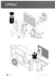
1. Bitte beachten Sie das Hauptinstallationsschema, das umseitig aufgeführt ist.<br />
2. Die geeignete Position ist im Abstand von 2 Meter zur <strong>ESC</strong>-<strong>pH</strong>-Systemsteuerung<br />
und 1,5 Meter über dem Erdboden. Stellen Sie den Chemikalien-Behälter so weit<br />
wie möglich von der Steuereinheit und dem Pumpenmodul wegen der<br />
Korrosionsgefahr weg. Der horizontale Abstand Steuereinheit, Pumpenmodul und<br />
Behälter soll mindestens 1 Meter betragen.<br />
3. Verwenden Sie die gleiche Montageanleitung wie bei der Steuereinheit. (siehe<br />
Handbuch)<br />
4. Anschluss des Pumpenmoduls an die Steuereinheit.<br />
Stecken Sie das Netzkabel in den Stecker im rechten unteren Teil der Steuer-<br />
Einheit<br />
5. Nehmen Sie den Behälterdeckel ab und spülen Sie ihn mit Wasser ab.<br />
6. Bohren Sie eine Öffnung von 9 mm in die Deckelmitte. Schieben Sie den<br />
transparenten Schlauch durch den Deckel und dann durch ein Schlauchgewicht<br />
und schließen Sie den Schlauch an das Steuerventil an. Der durchgeschobene<br />
Schlauch muss lang genug sein, damit das Gewicht an den Behälterboden<br />
gelangen kann.<br />
7. Setzen Sie den Deckel auf den Säurebehälter wieder auf.<br />
8. Stellen Sie den Behälter mit Chemikalien so weit wie möglich von der<br />
Steuereinheit und dem Pumpenmodul weg wegen der Korrosionsgefahr durch<br />
Verdunstungen. Der horizontale Abstand Pumpenmodul und Behälter soll<br />
mindestens 1 Meter betragen.<br />
9. Montieren Sie mit Hilfe von PVC-Kleber das Sonden-/Injektor-Gehäuse in die<br />
Einsaug- bzw. Rückflussleitung (Die Sonde muss horizontal zum Boden sein).<br />
ACHTUNG: Wenn die Rückflussleitung einen hohen Rückflussdruck aufweist,<br />
verwenden Sie die Saugleitung. Das Gehäuse ist für 50-mm-Standardfittings
gerichtet inkl. Reduktionen für 40-mm Verrohrung. Das Gehäuse muss mit den<br />
Pfeilen in Flussrichtung des Wassers eingebaut werden.<br />
EIN WICHTIGER HINWEIS: ACHTEN SIE BITTE DARAUF, DASS DIE SONDE<br />
IMMER FEUCHT IST. WENN ES NÖTIG IST, MONTIEREN SIE IN DIE<br />
POOLFILTERLEITUNG EIN EINWEGVENTIL, SO DAß ES ZU KEINEM<br />
AUSTRITT VON WASSER IN DIE KANALISATION KOMMEN KANN. WENN<br />
DIE SONDE AUSTROCKNET, KANN ES ZU EINER IRREVERSIBLEN<br />
SENSORB<strong>ESC</strong>HÄDIGUNG KOMMEN. IN DIESEM FALLE ERLISCHT DIE<br />
GARANTIE.<br />
10. Entfernen Sie den Deckel von der Sensorsonde und schrauben Sie die Sonde in<br />
das Gehäuse ein. Bewahren Sie die Sensorabdeckung auf um sie später bei<br />
einem Sensorausbau wieder verwenden zu können.<br />
11. Schließen Sie den Kabel der Sensorsonde unten an den Anschluss der<br />
Steuereinheit an. Achten Sie darauf, dass kein Wasser auf den Anschluss kommt.<br />
Es könnte zu einer Betriebsstörung führen und ev. zu einer Sondenbeschädigung<br />
und so zum Erlöschen der Garantie.<br />
12. Montieren Sie den Injektor am Gehäuse und schließen Sie die transparenten 6-<br />
mm- Schläuche an. Den transparenten Schlauch kann man mit Heißwasser weich<br />
machen und so den Anschluss erleichtern. Die Schlauchfarbe kann sich mit der<br />
Zeit ändern und/oder der Schlauch kann undurchsichtig erscheinen.<br />
13. Drücken Sie den Schlauch in die Anschlüsse an der Dosierpumpe – in der Nähe<br />
der Pfeile, die nach unten zeigen und sichern Sie es mit Hilfe von<br />
Plastikklemmen, die mitgeliefert wurden.<br />
14. Schließen Sie den transparenten Schlauch aus dem Chemikalien-Behälter an und<br />
dann montieren Sie den Schlauch wie vorher beschrieben.<br />
15. Achten sie bitte darauf, dass die Salzsäure richtig verdünnt wird: 1 Teil Salzsäure<br />
und 2 Teile Wasser. Wenn Sie Schwefelsäure benutzen, darf ihre Konzentration<br />
10% nicht übersteigen.<br />
16. Achten sie bitte darauf, dass der Schlauch im Pumpenmodul alle 6 Monate<br />
gewechselt werden muss.<br />
ERSTE INBETRIEBNAHME<br />
1. Nach der Installation lassen Sie die <strong>pH</strong>-Steuerung ausgeschaltet und lassen Sie<br />
die Poolpumpe 1 Stunde lang laufen.<br />
2. Mit Hilfe des Testkits messen Sie den <strong>pH</strong>-Wert.<br />
3. Mit Hilfe eines mitgelieferten Schraubendrehers drehen Sie CAL-Schraube so<br />
lange, bis der <strong>pH</strong>-Wert dem gemessenen Wert entspricht, den Sie mit dem Testkit<br />
gemessen haben. Auf dem Display erscheinen abwechselnd der <strong>pH</strong>-Wert und die<br />
Chlor-Produktion. Aus diesem Grunde kann die richtige Einstellung einige Zeit<br />
dauern.<br />
4. Schalten Sie die <strong>pH</strong>-Steuerung auf SET um und wenn es nötig ist, stellen Sie den<br />
gewünschten <strong>pH</strong>-Wert ein. BEMERKUNG: Bei den Pools aus Beton ist es<br />
möglich, dass der eingestellte <strong>pH</strong>-Wert von 7.4 oder niedriger zu einem höheren
Säureverbrauch führen wird. Es muss dann mehr Säure dosiert werden. Um<br />
diesen Effekt zu reduzieren, ist es wirtschaftlicher den Wert auf 7.7 einzustellen.<br />
Weitere Beratung bekommen Sie von Ihrem Poolfachmann.<br />
5. Schalten Sie die <strong>pH</strong>-Steuerung auf RUN und lassen Sie die Steuereinheit in<br />
Betrieb.<br />
6. In den folgenden Tagen überprüfen Sie mit Hilfe des Testkits den <strong>pH</strong>-Wert im<br />
Pool wieder. Wenn es nötig ist, stimmen Sie die Steuerung fein ab.<br />
WEB: www.monarchpoolsystems.com<br />
HEAD OFFICE: 12 Kembla Way, Willetton, Western Australia 6155<br />
Telephone: 61-8-9354-2600 Fax: 61-8-9457-9229<br />
General Importeur:<br />
Monarch Pool Systems Central & Eastern Europe<br />
Hauptstrasse 11, 1140 Wien, Austria<br />
Tel: + 43 1 577 3557, Fax: + 43 1 577 3656<br />
Email: monarchaustria@aol.com, www.pooldoktor.com
Ecomatic® <strong>ESC</strong>-<strong>pH</strong> <strong>SYSTEM</strong> - MANUAL ADDENDUM<br />
The <strong>ESC</strong>-<strong>pH</strong> system is a combination of a Ecomatic® <strong>ESC</strong> Salt Water Pool System<br />
and automatic <strong>pH</strong> Monitor/Controller. Please refer to the ESR/<strong>ESC</strong> Manual for<br />
information on how to operate the Ecomatic®. This manual covers the <strong>pH</strong> Control<br />
Features of the <strong>ESC</strong>-<strong>pH</strong> system. In the instrument panel the <strong>pH</strong> Control system<br />
controls are located in the dark-colored area marked “<strong>pH</strong> CONTROL”. It should be<br />
noted that the Ecomatic® operation is similar to but not exactly the same as the <strong>ESC</strong><br />
system described in the ESR/<strong>ESC</strong> manual, for example a display of the output<br />
control setting is not available.<br />
THE DIGITAL DISPLAY<br />
The digital display is used to provide information on the Ecomatic® output,<br />
<strong>pH</strong> and <strong>pH</strong> set point.<br />
The display will alternately show the chlorinator production and <strong>pH</strong><br />
When the <strong>pH</strong> Control switch is placed in the SET position the display will<br />
show the <strong>pH</strong> set point<br />
FEED & <strong>pH</strong> STATUS LEDs<br />
The <strong>pH</strong> STATUS LED is used to indicate if the <strong>pH</strong> is within a range of ±0.3<strong>pH</strong> of the<br />
set point. If the <strong>pH</strong> is more than 0.3<strong>pH</strong> above the set point the LED will flash<br />
red/green. If the <strong>pH</strong> is less than 0.3<strong>pH</strong> below the set point the LED will flash red<br />
The FEED STATUS LED is used to indicate the operation of the acid dosing pump:<br />
RED<br />
ACID PUMP OFF<br />
GREEN<br />
ACID PUMP AVAILABLE<br />
GREEN FLASHING ACID PUMP IS DOSING<br />
<strong>pH</strong> CONTROL<br />
The control switch has three positions:<br />
RUN In this position the acid dosing pump will operate according to the<br />
value of the <strong>pH</strong> set point and measured <strong>pH</strong><br />
SET This will allow adjustment of the controller set point using adjustment<br />
tool. Turn clockwise to increase the set point. Note that acid pump is off when<br />
adjusting set point<br />
OFF Disables the acid dosing pump and control functions<br />
D<strong>ESC</strong>RIPTION OF OPERATION<br />
The <strong>pH</strong> control has been designed to provide an acid feed in proportion to the<br />
difference between the actual <strong>pH</strong> and the <strong>pH</strong> set point. The control also operates on<br />
a cycle to allow the acid being fed to mix with the pool water. The cycle is<br />
approximately five minutes duration. If the <strong>pH</strong> is 0.3 or more above the set <strong>pH</strong> at the<br />
start of a cycle the acid dosing pump will operate continuously until the <strong>pH</strong> falls below<br />
the set point plus 0.3<strong>pH</strong>. When this happens the amount of time the pump operates
each cycle will reduce as the <strong>pH</strong> gets closer to the set point. The acid dosing pump<br />
will turn off when the set point is reached. The proportional system is designed to<br />
keep <strong>pH</strong> relatively constant with little or no overshoot (<strong>pH</strong> falling below the set point).<br />
INSTALLING THE PUMP MODULE:<br />
IMPORTANT: KEEP BARE HANDS AWAY FROM POOL ACID AND ALWAYS<br />
USE CAUTION WHEN HANDLING POOL CHEMICALS.<br />
17. Refer general installation diagram on reverse of this page.<br />
18. Select a convenient position within 2 metres of the <strong>ESC</strong> <strong>pH</strong> Control System, and<br />
1.5 metres above ground level. Ensure chemical drum is placed as far away as<br />
possible from the Control Unit and Pump Module to avoid corrosive damage.<br />
Control Unit and Pump Module must be a minimum of 1.0 metre horizontally from<br />
drum.<br />
19. Use the same mounting procedures as for the Control Unit. (Refer manual).<br />
20. Connecting Pump Module to Control Unit.<br />
Plug the mains lead from the pump module into the GPO in the bottom right of<br />
the unit.<br />
21. Remove cap from drum and clean in water.<br />
22. Drill a 9mm hole through the centre of cap. Fit the clear tube through the cap,<br />
then the tube weight and attach the check valve to the tube, push enough tube<br />
through the cap to allow the tube weight to sit at the bottom of the drum.<br />
23. Re - fit cap to acid drum.<br />
24. Place chemical drum away from the Control Unit and Pump Module to avoid<br />
possible corrosive damage from chemical vapour. Minimum distance horizontally<br />
between Pump Module and Chemical Drum is 1.0 metres.<br />
25. Using PVC cement fit Probe/Injector Housing to suction or return line (and ensure<br />
probe is horizontal to the ground). NOTE: if return has a high backpressure use<br />
the suction line. The Housing has 50mm standard fittings with reducers supplied<br />
for 40mm applications. Ensure Housing is fitted with arrows pointing in the<br />
direction of water flow.<br />
IMPORTANT: ENSURE SENSOR PROBE ALWAYS REMAINS MOIST. A<br />
NON-RETURN VALVE MAY NEED TO BE FITTED IN POOL FILTRATION LINE<br />
TO STOP DRAINAGE IN THE PLUMBING. SENSOR PROBE MAY BE<br />
DAMAGED BEYOND REPAIR IF LEFT TO DRY OUT. WARRANTY WILL BE<br />
VOID IF THIS TYPE OF DAMAGE IS APPARENT.<br />
26. Remove cap from sensor probe, discard travel solution and screw into sensor<br />
housing. Keep cap in a safe place for future sensor removal.
27. Connect wire from sensor probe to the connector on the base of the control unit.<br />
Ensure water (garden sprayers, reticulation etc) does not splash or spray onto the<br />
connector. This is likely to cause erroneous operation and may damage the<br />
sensor probe, voiding warranty.<br />
28. Fit Injector to Housing and connect the 6mm diameter clear tubes. Cut Clear tube<br />
can be softened in hot water to enable easier connection. Tube may change<br />
colour and/or become opaque in use.<br />
29. Push tube onto barb connectors of dosing pump nearest arrows facing down and<br />
secure with plastic clamps provided.<br />
30. Connect clear tube from the chemical containers then fit tube as described<br />
previously.<br />
31. Ensure that hydrochloric acid is diluted by 1 Part Acid to 2 Parts water, if using<br />
Sulphuric Acid it must be no greater than 10% strength.<br />
32. Please ensure that you change the Tube in the pump module every 6 months.<br />
INITIAL SET-UP<br />
7. After installation leave <strong>pH</strong> Control off and run pool pump for an hour. While this is<br />
being done it is a good time to ensure that the pool balance is correct.<br />
8. Using a pool test kit measure the <strong>pH</strong>.<br />
9. Using the tool supplied adjust CAL until the <strong>pH</strong> display matches the test kit result.<br />
The display will alternate between <strong>pH</strong> and the chlorine cell production so this may<br />
take a little time to get right.<br />
10. Switch the <strong>pH</strong> Control to SET and adjust to the desired <strong>pH</strong> if necessary. NOTE:<br />
for concrete pools it is possible that a <strong>pH</strong> set point of around 7.4 or below will lead<br />
to high acid consumption and frequent additions of buffer. To reduce this effect a<br />
set point of 7.7 may be more economical. Refer your pool professional for further<br />
advice.<br />
11. Switch <strong>pH</strong> Control to RUN and allow unit to operate.<br />
12. Retest pool <strong>pH</strong> with test kit over the next few days to fine tune control if necessary<br />
WEB: www.monarchpoolsystems.com<br />
HEAD OFFICE: 12 Kembla Way, Willetton, Western Australia 6155<br />
Telephone: 61-8-9354-2600 Fax: 61-8-9457-9229
Distributor:<br />
MONARCH Pool Systems Central & Eastern Europe, Hauptstrasse 11, 1140 Vienna,<br />
Austria<br />
Tel: +43 1 5773557, Fax: +43 1 5773656, e-mail: monarchaustria@aol.com,<br />
www.pooldoktor.com
Ecomatic®<br />
SYSTÉM <strong>ESC</strong>-<strong>pH</strong> -<br />
DOPLNOK UŽÍVATEĽSKEJ PRÍRUČKY<br />
Systém <strong>ESC</strong>-<strong>pH</strong> je kombináciou systému Ecomatic® <strong>ESC</strong> učeného pre bazény so<br />
slanou vodou a automatického monitoru/regulátora <strong>pH</strong>. Informácie o tom, ako<br />
pracovať so zariadením Ecomatic® nájdete v Užívateľskej príručke ESR/<strong>ESC</strong>. Táto<br />
užívateľská príručka sa venuje prvkom regulovania <strong>pH</strong> systému <strong>ESC</strong>. Na<br />
prístrojovom paneli sú kontrolky systému regulovania <strong>pH</strong> umiestnené v tmavo<br />
sfarbenej časti, ktorá je označená ako<br />
“<strong>pH</strong> CONTROL”. Je dôležité uvedomiť si, že prevádzka systému Ecomatic® je<br />
podobná, ale nie úplne rovnaká, ako prevádzka systému <strong>ESC</strong>, popísaného v<br />
užívateľskej príručke ESR/<strong>ESC</strong>. Napríklad zobrazenie výstupných kontrolných<br />
nastavení nie je k dispozícii.<br />
DIGITÁLNY DISPLEJ<br />
Digitálny displej sa používa na poskytovanie informácií o výkone Ecomatic®,<br />
o <strong>pH</strong> a nastavenej hodnote <strong>pH</strong>.<br />
Displej striedavo zobrazuje produkciu chlorátora a <strong>pH</strong><br />
Keď je ovládací spínač <strong>pH</strong> v polohe SET (NASTAVENÉ), na displeji bude<br />
zobrazená nastavená hodnota <strong>pH</strong><br />
LED diódy STAVU DÁVKOVANIA a <strong>pH</strong><br />
LED dióda STAVU <strong>pH</strong> sa používa na určenie toho, či je <strong>pH</strong> v rozsahu ±0.3<strong>pH</strong><br />
nastavenej hodnoty. Ak je <strong>pH</strong> vyššie ako 0,3 <strong>pH</strong> nad nastavenou hodnotou, LED<br />
dióda bude blikať červeno/zeleno. Ak je <strong>pH</strong> nižšie ako 0.3 <strong>pH</strong> pod nastavenou<br />
hodnotou, LED dióda bude blikať červeno<br />
LED dióda STAVU DÁVKOVANIA sa používa na indikáciu prevádzky čerpadla na<br />
dávkovanie kyseliny:<br />
ČERVENÁ<br />
ČERPADLO KYSELINY VYPNUTÉ<br />
ZELENÁ<br />
ČERPADLO KYSELINY DOSTUPNÉ<br />
BLIKÁ ZELENÁ<br />
ČERPADLO KYSELINY DÁVKUJE<br />
REGULÁCIA <strong>pH</strong><br />
Ovládací spínač má tri polohy:<br />
RUN (BEŽÍ) V tejto polohe bude čerpadlo na dávkovanie kyseliny pracovať<br />
na základe nastavenej hodnoty <strong>pH</strong> a nameraného <strong>pH</strong><br />
SET (NASTAVENIE) Umožňuje nastavenie nastavenej hodnoty regulátora<br />
pomocou regulačného nástroja. Otočením v smere hodinových ručičiek<br />
zvýšite nastavenú hodnotu. Dbajte na to, aby bolo čerpadlo kyseliny počas<br />
nastavovania nastavenej hodnoty vypnuté<br />
OFF (VYPNUTÉ) Vypne čerpadlo na dávkovanie kyseliny a funkcie<br />
regulovania
POPIS ČINNOSTI<br />
Regulovanie <strong>pH</strong> bolo navrhnuté tak, aby zabezpečovalo dodávanie kyseliny pomerne<br />
rozdielu medzi skutočným <strong>pH</strong> a nastavenou hodnotou <strong>pH</strong>. Regulátor pracuje cyklicky,<br />
čím umožňuje, aby sa dávkovaná kyselina zmiešala s vodou v bazéne. Cyklus trvá<br />
približne päť minút. Ak je na začiatku cyklu <strong>pH</strong> 0,3 alebo viac nad nastaveným <strong>pH</strong>,<br />
čerpadlo na dávkovanie kyseliny bude pracovať nepretržite, kým <strong>pH</strong> neklesne pod<br />
nastavenú hodnotu plus 0,3<strong>pH</strong>. Keď sa to stane, časové obdobie, počas ktorého<br />
bude čerpadlo pracovať v každom cykle, sa bude znižovať v závislosti od toho, ako<br />
sa bude <strong>pH</strong> približovať k nastavenej hodnote. Čerpadlo na dávkovanie kyseliny sa<br />
vypne, keď sa dosiahne nastavená hodnota. Proporcionálny systém je navrhnutý tak,<br />
aby udržiaval <strong>pH</strong> na relatívne konštantnej úrovni a aby dochádzalo len k malému,<br />
prípadne žiadnemu presahu (poklesu <strong>pH</strong> pod nastavenú hodnotu).<br />
INŠTALOVANIE MODULU ČERPADLA:<br />
DÔLEŽITÁ INFORMÁCIA: NEDOTÝKAJTE SA HOLÝMI RUKAMI KYSELINY<br />
URČENEJ PRE BAZÉN A PRI MANIPULÁCII S CHEMIKÁLIAMI URČENÝMI PRE<br />
VÁŠ BAZÉN BUĎTE VŽDY OPATRNÝ.<br />
33. Riaďte sa hlavnou schémou inštalácie, ktorá je uvedené na opačnej strane.<br />
34. Zvoľte si vhodnú polohu vo vzdialenosti do 2 metrov od systému regulácie<br />
<strong>ESC</strong><strong>pH</strong> a 1,5 metra nad úrovňou zeme. Zabezpečte, aby bol sud s chemikáliou<br />
umiestnený čo možno najďalej od regulátora a modulu čerpadla, čím zabránite<br />
ich poškodeniu v dôsledku korózie. Regulátor a modul čerpadla musia byť<br />
horizontálne vzdialené minimálne 1,0 meter od nadoby s <strong>pH</strong> -.<br />
35. Použite rovnaký montážny postup ako u regulátora. (Riaďte sa pokynmi<br />
uvedenými v užívateľskej príručke).<br />
36. Pripojenie modulu čerpadla k regulátoru.<br />
Zapojte sieťovú šnúru z modulu čerpadla do konektoru v pravej dolnej časti<br />
jednotky.<br />
37. Odstráňte veko z nadoby s <strong>pH</strong> minus a vypláchnite ho vodou.<br />
38. V strede veka navŕtajte 9 mm otvor. Prestrčte cez veko priehľadnú trubicu, potom<br />
závažie trubice. Prestrčte cez veko dostatočne dlhú časť trubice, aby závažie<br />
trubice mohlo klesnúť až na dno suda.<br />
39. Znovu nasaďte veko na nadobu s <strong>pH</strong> minus.<br />
40. Umiestnite nadobu s chemikáliou čo najďalej od regulátora a modulu čerpadla,<br />
čím zabránite ich možnému poškodeniu spôsobenému chemickými výparmi.<br />
Minimálna horizontálna vzdialenosť medzi modulom čerpadla a nadobou s<br />
chemikáliou je 1,0 meter.
41. Pomocou PVC tmelu nasaďte plášť sondy/injektora na sacie alebo vratné<br />
vedenie (a zabezpečte, aby sonda bola horizontálne so zemou). POZNÁMKA: Ak<br />
má vratné vedenie vysoký spätný tlak, použite sacie vedenie. Plášť má<br />
štandardnú 50 mm armatúru s redukciou dodávanou pre 40 mm aplikácie.<br />
Zabezpečte, aby bol plášť vybavený šípkami, ktoré ukazujú smer vodného toku.<br />
DÔLEŽITÉ UPOZORNENIE: ZABEZPEČTE, ABY SONDA SNÍMAČA BOLA<br />
VŽDY VLHKÁ. V PRÍPADE POTREBY NAMONTUJTE DO FILTRAČNÉHO<br />
VEDENIA BAZÉNA SPATNY VENTIL, KTORÝ ZABRÁNI ÚNIKOM DO<br />
KANALIZÁCIE. AK NECHÁTE SONDU VYSCHNÚŤ, MÔŽE DÔJSŤ K<br />
NEOPRAVITEĽNÉMU POŠKODENIU SONDY. V PRÍPADE, ŽE DOŠLO K<br />
TAKÉMU TYPU POŠKODENIA, STRÁCA ZÁRUKA PLATNOSŤ.<br />
42. Odstráňte kryt zo sondy snímača, vypustite prepravný roztok a priskrutkujte ju na<br />
plášť snímača. Odložte kryt na bezpečné miesto pre použitie pri ďalšej<br />
demontáži snímača.<br />
43. Pripojte vodič zo sondy snímača na konektor na pätke regulátora. Zabezpečte,<br />
aby voda (zo záhradných postrekovače, sietí, atď.) nešpliechala a nestriekala<br />
na konektor. Mohlo by to spôsobiť chybnú prevádzku a poškodiť sondu snímača,<br />
čím by došlo k strate platnosti záruky.<br />
44. Namontujte injektor na plášť a pripojte priehľadnú trubicu so 6 mm priemerom.<br />
Odrezanú priehľadnú trubicu môžete zmäkčiť v horúcej vode, čím uľahčíte jej<br />
pripojenie. Trubica môže počas používania zmeniť farbu a/alebo sa stať<br />
nepriehľadnou.<br />
45. Zatlačte trubicu do svorky s háčkom na dávkovacom čerpadle tak, aby najbližšie<br />
šípky smerovali nadol a zaistite ju plastovými svorkami, ktoré tvoria súčasť<br />
dodávky.<br />
46. Pripojte priehľadnú trubicu z nádrže s <strong>pH</strong> minus a potom namontujte trubicu tak,<br />
ako to bolo popísané v predchádzajúcej časti.<br />
47. Ak pouzivate HCl, zabezpečte, aby bola zriedená v pomere 1 diel kyseliny na 3<br />
diely vody. Jej koncentrácia nesmie prevýšiť 10%.<br />
48. Výmenu trubice v module čerpadla je potrebné vykonať každých 6 mesiacov.<br />
PRVÉ SPUSTENIE<br />
13. Po inštalácii nechajte regulátor <strong>pH</strong> vypnutý a nechajte bežať bazénové čerpadlo<br />
počas jednej hodiny. Počas tohoto obdobia sa môžete presvedčiť, že pomer v<br />
bazéne je správny.<br />
14. Pomocou testovacieho balíčka zmerajte <strong>pH</strong>.<br />
15. Pomocou dodaného nástroja upravte CAL tak, aby sa údaj <strong>pH</strong> zhodoval s<br />
výsledkom testovacieho balíčka. Na displeji sa bude striedavo zobrazovať<br />
hodnota <strong>pH</strong> a produkcia chlóru, takže správne nastavenie môže trvať určitý čas.<br />
16. Prepnite regulátor <strong>pH</strong> na SET a v prípade potreby nastavte požadované <strong>pH</strong>.<br />
POZNÁMKA: U betónových bazénov je možné, že <strong>pH</strong> nastavené na hodnotu<br />
približne 7,4 alebo nižšie bude mať za následok vyššiu spotrebu kyseliny, čo si
vyžaduje častejšie pridávanie tlmiaceho roztoku. Ak chcete zredukovať tento<br />
efekt, bude ekonomicky výhodnejšie nastaviť hodnotu na 7,7. Ďalšie rady<br />
získate u odborníka na bazény.<br />
17. Prepnite regulátor <strong>pH</strong> na RUN a nechajte jednotku v činnosti.<br />
18. Počas nasledujúcich dní opätovne otestujte <strong>pH</strong> bazéna pomocou testovacieho<br />
balíčka, aby ste v prípade potreby doladili reguláciu.<br />
WEB: www.monarchpoolsystems.com<br />
HEAD OFFICE: 12 Kembla Way, Willetton, Western Australia 6155<br />
Telefón: 61-8-9354-2600 Fax: 61-8-9457-9229<br />
ABN 84 361 768 704 A.C.N. 009 380 509<br />
E-MAIL: info@Promatic.net.au<br />
Legenda k obrázku:<br />
<strong>ESC</strong>-<strong>pH</strong><br />
Installation Diagram - Schéma inštalácie<br />
Acid - Kyselina<br />
Acid IN - Kyselina dnu<br />
Liguid Pool Acid - Tekutá kyselina pre bazény<br />
Hose weight and non-returnable valve - Závažie hadice a nevratný ventil<br />
Dosing Pump - Dávkovacie čerpadlo<br />
Power cable - Sieťový kábel<br />
Return to pool line - Vratné vedenie do bazéna<br />
Accessories - Príslušenstvo<br />
Filter - Filter<br />
Pump - Čerpadlo<br />
Suction line - Sacie vedenie<br />
Cell Cable - Kábel článku<br />
To Mains Power 230 V - do siete 230 V<br />
(control unit supplied only when pump is ON) - (prúd do regulačnej jednotky je<br />
dodávaný len<br />
keď je čerpadlo ZAPNUTÉ)