Montageanleitung Trennfunkenstrecken EXFS L 100 ... - EuroVolt
Montageanleitung Trennfunkenstrecken EXFS L 100 ... - EuroVolt
Montageanleitung Trennfunkenstrecken EXFS L 100 ... - EuroVolt
- Keine Tags gefunden...

Sie wollen auch ein ePaper? Erhöhen Sie die Reichweite Ihrer Titel.
YUMPU macht aus Druck-PDFs automatisch weboptimierte ePaper, die Google liebt.
<strong>Montageanleitung</strong><strong>Trennfunkenstrecken</strong><strong>EXFS</strong> L <strong>100</strong>, <strong>EXFS</strong> L 200, <strong>EXFS</strong> L 300,<strong>EXFS</strong> L ...Sonderlängenanwendbar im EX-Bereich (Zone 2)Zum indirekten Verbinden/Erden betriebsmäßig getrennter AnlagenteileBlitzschutz-Potentialausgleich© COPYRIGHT 2007 DEHN + SÖHNE/ protected by ISO 16016BlitzschutzÜberspannungsschutzArbeitschutzPublication No. 1010 / UPDATE 09.07 Id-No. 047145
1. AnwendungDie Trennfunkenstrecke dient zur indirekten Verbindung betriebsmäßig getrennter Anlagenteile,z.B. getrennter Erdungsanlagen. Sie kann zur indirekten Überbrückung von Isolierstücken,Isolierkupplungen und Isolierflanschen an kathodisch geschützten Anlagenteilen, z.B. Pipelinesoder Tanks als Maßnahme zum Blitzschutz-Potentialausgleich nach DIN VDE 0185 eingesetztwerden.2. SicherheitshinweiseDie Trennfunkenstrecke darf nur von einer Elektrofachkraft unter Berücksichtigung der einschlägigenDIN VDE-Bestimmungen eingesetzt werden. Ebenso sind bei der Errichtung der Trennfunkenstreckein explosionsgeschützten Bereichen oder in Anlagen mit kathodischen Korrosionsschutz-Stromanlagen (KKS-Anlagen) die jeweils zutreffenden Richtlinien zu beachten. Beispielhaft seihier auf die DIN VDE 0185, DIN VDE 0165 und AfK-Empfehlung Nr. 5 * ) verwiesen.Der Einsatz ist nur im Rahmen der in dieser <strong>Montageanleitung</strong> genannten und gezeigtenBedingungen zulässig. Dies betrifft im besonderen den Abschnitt 4, bei dem die nach der AfK-Empfehlung Nr. 5 zu beachtende Isolationskoordination aus Sicherheitsgründen einzuhaltenund ggf. im montierten Zustand zu überprüfen ist. Bei Belastungen, die über den ausgewiesenenWerten liegen, kann es zur Zerstörung der Trennfunkenstrecke kommen. Vor dem Einbau istdie Trennfunkenstrecke durch die Elektrofachkraft auf äußere Beschädigungen zu kontrollieren.Sollte bei dieser Kontrolle eine Beschädigung oder ein sonstiger Mangel festgestellt werden,darf die Trennfunkenstrecke nicht eingebaut werden.Zusätzlich ist die, dieser <strong>Montageanleitung</strong> angefügte Konformitätsaussage, sowie die zugehörige1. Ergänzung nach der Richtlinie 94/9/EG zu beachten.Achtung:Öffnen Sie niemals das Gerät. Durch das Öffnen oder jeden sonstigen Geräteeingriff,insbesondere die Verlängerung des Anschlusskabels, kann die Schutzwirkung beeinträchtigtwerden (siehe Pkt. 4). Bei Geräteeingriff oder Veränderung erlischt die Gewährleistung.<strong>EXFS</strong> L <strong>100</strong>, <strong>EXFS</strong> L 200, <strong>EXFS</strong> L 300, <strong>EXFS</strong> L ...SonderlängeTrennfunkenstrecke <strong>EXFS</strong> L ....Explosionsschutz nachEN 50021: EEx nC II T4 zum Einsatz inZone 2 gemäß: DIN VDE 0165-1,Richtlinie 94/9EGGerätekategorie 3KonformitätsaussageNr. Ex: ZELM 03 ATEX 3192X(ZELM Ex Braunschweig)für <strong>EXFS</strong> L... Art.-Nr. 923 060,923 061, 923 062, 923 006,*) Nennspannung U n 25 VAnsprechwechselspannung 50 Hz U aw £ 1.2 k V<strong>100</strong>%-Ansprech- U as <strong>100</strong> £ 2.5 kVBlitzstoßspannung (1.2/50 ms)Nennableitstoßstrom (8/20 ms) I n <strong>100</strong> kABlitzstoßstrom (10/350 ms) I imp 50 kA*) 25 V darf in Anlagen des kathodischen Korrosionsschutzes nicht überschrittenwerden!2
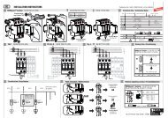
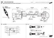
3. Montagehinweise3.1Der Einbau hat nach den für den Einsatzort geltenden Vorschriften (z.B. AfK-Empfehlungen,DIN VDE 0165-1 (EN 60079-14)) zu erfolgen. Zusätzlich gilt die (DIN V VDE V 0185-3,Hauptabschnitt 2, Abschnitt 4.3.3.2).3.2 Bei der Installation der Trennfunkenstrecke zum Schutz von elektrischen Trennstellen(z.B. Isolierflanschen) ist vor Durchführung der Installationsarbeiten an der elektrischenTrennstelle diese für die Dauer der Arbeiten mit einem flexiblen, isolierten Kupferseilleitend zu überbrücken. Der hierfür erforderliche Seilquerschnitt ist der AfK-EmpfehlungNr. 5*) sowie dem Arbeitsblatt GW 9 "Elektrische Überbrückung bei Rohrtrennungen",herausgegeben vom DVGW, zu entnehmen.Achtung Funkenbildung!Beim Herstellen der Verbindung ist sicherzustellen, dass keine zündfähige Atmosphärevorhanden ist!Hinweis:Zur Überbrückung von Rohrleitungen kann z.B. die DEHN-Kettenrohrschelle Art.-Nr.413 000 verwendet werden!3.3 Beim Einbau der Trennfunkenstrecke ist darauf zu achten, dass an der Seilaustrittsstellekeine Feuchtigkeit zwischen Seilaustritt und dem metallenen Gehäuse der Trennfunkenstreckeeindringen kann (siehe Bild 3a).3.4 Die Trennfunkenstrecke ist deshalb senkrecht einzubauen (Seilaustritt nach unten zeigend).Der senkrechte Einbau lässt sich sowohl bei senkrechter als auch bei waagerechterFlanschmontage durch Verwendung entsprechender Anschlussbügel IF 1 (IF 3) erreichen(siehe Bild 3b, 3c und 3d, Seite 4 und 5).Bild 3a SeilaustrittMetallgehäuseder TrennfunkenstreckeSeilaustritt3
Hinweise für die Montage der Trennfunkenstrecke an SchraubflanschenE Die Anschlussbügel müssen die Kontaktfläche am Isolierstückgroßflächig elektrisch kontaktieren (Lackschichten oder sonstigeBeläge sind zu entfernen).IFF Durch die Montage der Trennfunkenstrecke darf die Isolationsfähigkeitdes Isolierstückes nicht herabgesetzt werden. Dazu muss dieIsolierung der Flanschschraube weiterhin durchgängig sein.Im Idealfall sollte die Isolierhülse für den Schraubenschaftetwa 2 - 3 mm in die Bohrung der Isolierscheibenhineinragen (siehe Teilbild F ).F!FCTeilbildFlanschverschraubung(isoliert)EAnschlussbügelIF 1 (IF 3)E F!EDie AnschlussbügelIF 1 (IF 3) müssenleitend mit denRohrleitungsflanschenverbunden sein!Auf durchgängigeIsolierungachten!Bild 3d Ausführungsbeispiel (Rohrflansch, horizontale Anordnung)H = (H min + H max ) / 2FCH maxIF 3L IF 1H minS L³ 0,5 L5
4. Hinweis zur Isolationskoordination nach AfK-Empfehlung Nr. 5 (02/86)*Die Installation der Trennfunkenstrecke am Isolierstück erfordert eine Koordination seinerPrüfwechselspannung mit der vom Blitzstrom durchflossenen Installationsschleife, diesich im wesentlichen aus der Konfiguration der Kabellänge L und der Anschlusshöhe Hüber der zu überbrückenden Strecke S L eines Isolierstückes ergibt (siehe Bild3c, 3d). Damit wird verhindert, dass die in der Installationsschleife H x L erzeugteSpannung die Isolation der Trennstelle durch- oder überschlägt und so einenzündenden Lichtbogen erzeugt bzw. die Isolation der Trennstelle dauerhaft beschädigt.Die dazu erforderlichen Koordinationswerte können dem Diagramm (siehe Seite 7)entnommen werden, indem die unter der jeweiligen Einbausituation ermittelten Wertefür die Kabellänge L und der Anschlusshöhe H in das Diagramm übertragen und dersich daraus ergebende Wert der Prüfspannung U PW ermittelt wird. Dieser Wertentspricht der für die jeweilige Konfiguration erforderlichen Prüfwechselspannung(Effektivwert) der Trennstelle (z.B. der eines Isolierstückes).Diese erforderliche Prüfwechselspannung muss gleich oder kleiner als der für die Trennstelleausgewiesene vergleichbare Wert sein (z.B. 5 kV). Ist diese Bedingung nichterfüllt, so kann über die Zuschaltung weiterer Ableitungen (<strong>Trennfunkenstrecken</strong>) eineAnpassung vorgenommen werden. Dabei wird die Anzahl der Ableitungen Z so langeerhöht, bis sich aus deren Multiplikation mit der ausgewiesenen Prüfwechselspannungder Trennstelle ein Wert ergibt, der gleich oder größer als der Wert für U PW aus demDiagramm ist.U PW £ U N x ZU PW : Effektivwert der für eine Koordination erforderlichen Prüfwechselspannung der Trennstelle (kV)U N : Effektivwert der Nenn-Prüfwechselspannung der Trennstelle (kV)Z : Anzahl der zur Koordination erforderlichen Parallel-Ableitungen (<strong>Trennfunkenstrecken</strong>)Beispiel:Aus einer gegebenen Installationsvariante werden nach Bild 3c folgende Werte ermittelt:L: 0,5 mH: 0,1 m Þ Diagramm: U PW= 14,5 kVDie für die Trennstelle ausgewiesene Prüfwechselspannung U N beträgt 5 kVZ ³ U PW / U NZ ³ 14,5 kV / 5 kVZ = 36
<strong>100</strong>9080707Prüfspannung U PW (kV)6050403020<strong>100</strong>0,1 0,2 0,3 0,5 0,75 1 1,5 2 2,5 3H = 0,2 mKabellänge L (m)H = 0,15 mH = 0,1 mH = 0,05 mH = 0,025 m
In dem beschriebenen Beispiel muss also eine Koordination der Kabellänge L mitder Nenn-Prüfwechselspannung des Isolierstückes durch 3 parallel angeordnete Ableitungen(<strong>Trennfunkenstrecken</strong>) hergestellt werden.Hinweis:Das Anschlusskabel (Kabellänge, Leiterquerschnitt und - anschluss) darf aus Gewährleistungsgründennur vom Hersteller geändert werden. Kabellängen, die länger sind als 0,3 m, sindSonderausführungen (Sonderlängen), die nach Kundenangaben werkseitig konfektioniertsind. Die Sonderlängen sind durch ein entsprechendes Hinweisschild mit Angabe der KabellängeL gekennzeichnet.5. Wartung und BetriebDie Trennfunkenstrecke ist wartungsfrei. Eine Überbeanspruchung verursacht in der Regelein Verschweißen/Kurzschluss der Elektroden.Bei Systemen mit einer KKS-Anlage wird die Überbeanspruchung der Trennfunkenstreckedurch die Potentialanzeige der KKS-Anlage erfasst.Eine defekte Trennfunkenstrecke kann auch durch eine einfache Widerstandsmessung(Meßwert
Notiz
Installation InstructionsIsolating Spark Gaps<strong>EXFS</strong> L <strong>100</strong>, <strong>EXFS</strong> L 200, <strong>EXFS</strong> L 300,<strong>EXFS</strong> L ... Special Cable LengthsFor application in explosive areas (Zone 2)For indirect connecting/earthing functionally separate parts of installationsLightning Equipotential Bonding© COPYRIGHT 2007 DEHN + SÖHNE/ protected by ISO 16016Lightning ProtectionSurge ProterctionSafety EquipmentPublication No. 1010/ UPDATE 09.07 Id-No. 047145
1. ApplicationAn isolating spark gap connects indirectly functionally separate parts of an installation, e.g.isolated earth-termination systems. It can be used for bridging insulating pieces, insulatingcouplings and insulating flanges indirectly at cathodic protected parts of an installation, e.g.pipelines or tanks, as a measure of lightning equipotential bonding according to DIN VDE 0185.2. Safety instructionsThe isolating spark gap may be mounted by a skilled electrician only, under consideration ofthe relevant national regulations (Germany: DIN VDE standards). For installing the isolatingspark gap into areas protected against explosion or installations with cathodic corrosionprotection (CP installations) the relevant directives have also to be taken into account. Forexample, see also DIN VDE 0185, DIN VDE 0165 and AfK recommendation No. 5* ) .The use is permissible only within the scope of the conditions stated and shown in the presentinstallation instructions. This applies especially to section 4, which provides that the insulationcoordination to be observed in accordance with AfK recommendation No. 5 has to be consideredfor safety reasons. If required, this has to be tested after installation. Loads exceeding the valuesindicated may destroy the isolating spark gap. Before installation, the electrician has to checkthe isolating spark gap for external damage. If he finds any damage or other fault, the isolatingspark gap must not be installed.Furthermore, the conformity statement enclosed to these installation instructions has to beobserved, as well as the respective 1. Amendment of Directive 94/4/EC.Warning!Never open the device. Opening or any other kind of intervention, especially extending theconnecting cable, may impair the protective effect (see section 4). Any modificationinvalidates the warranty.<strong>EXFS</strong> L <strong>100</strong>, <strong>EXFS</strong> L 200, <strong>EXFS</strong> L 300, <strong>EXFS</strong> L ...Special cable lengthIsolating spark gap <strong>EXFS</strong> L ...Explosion protection according toEN 50021: EEx nC II T4 for use inZone 2 according to: DIN VDE 0165-1,Directive 94/9ECDevice Category 3Conformity StatementNo. Ex:ZELM 03 ATEX 3192X(ZELM Ex Brunswick, Germany)for <strong>EXFS</strong> L ..., Part Nos. 923 060,923 061, 923 062, 923 006*) Nominal Voltage U n 25 VPower frequency voltage 50 Hz U aw £ 1.2 k V<strong>100</strong>%-Lightning impulse sparkovervoltage (1.2/50 ms) U as <strong>100</strong> £ 2.5 kVNominal discharge current (8/20 ms) I n <strong>100</strong> kALightning impulse current (10/350 ms) I imp 50 kA*) 25 V must not be exceeded in installations of cathodic protection against corrosion12
3. Installation instructions3.1 The device has to be installed according to the regulations applying to the installation site(e.g. AfK recommendations, EN 60079-14 (DIN VDE 0165-1)). In addition applies DIN V VDEV 0185-3 (Main Section 2, Subclause 4.3.3.2).3.2 When installing the isolating spark gap for protection of electrical isolating points (e.g.insulating flanges), the spark gap has to be bridged conductively at the electrical isolatingpoint with a flexible insulated copper cable for the duration of the installation work. The cablecross section required for this purpose has to be taken from AfK recommendation No. 5* )as well as from the process sheet GW 9 ”Elektrische Überbrückung bei Rohrtrennungen”[engl.: ”Electrical bridging for separating pipes”], published by DVGW.Warning! Sparkings!When establishing the connection, it has to be ensured that no ignitable atmosphere isexisting!Note:For bridging pipelines, e.g. DEHN chain pipe clamp, Part No. 413 000, can be used.3.3 When installing the isolating spark gap, it has to be ensured that no humidity can enterbetween the cable outlet and the metal enclosure of the isolating spark gap (see Fig. 3a).3.4 Therefore the isolating spark gap has to be installed vertically (cable outlet downwards).It can be installed both with vertically and horizontally installed flanges by using correspondingIF 1 (IF 3) connection brackets (see Figs. 3b, 3c, pages 14 and 15).Fig. 3a Cable outletmetal sparkgap enclosurecable outlet13
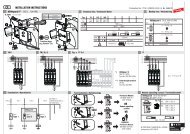
3.5 The connection brackets have to be mounted according to Figs. 3b, 3c and 3d (see alsoFig. c, page 15). The connecting cable and connection brackets have to go with thedimensions of the flanges (see also section 4). The connecting cable has to be connectedvia the isolating point as directly as possible (see Figs. 3c and 3d).3.6 All connections have to be secured against self-loosening by means of spring washers.The connecting parts have to be protected against corrosion.3.7 If required, and according to installation site, the electrical isolating point as well as allbare metal connecting parts have to be protected against unintended bridging.Fig. 3b Connection bracketIF 3 (2 ST.)Part No. 923 016IF 1 (2 ST.)Part No. 923 011SizeTerminal height"H"of available connectionbrackets (m)Hd1d1max. 60 mmHIF 1 IF 31 0.08 0.12 0.1 0.123 0.14 ---top viewside viewFig. 3c Application example (pipe flange, vertical arrangement)Cbolted flange joint(insulated)IF 1AM10 screwS LBspring washerAHIF 1LB10 Nm14
Instructions for mounting the isolating spark gap at screw flangesE The connection brackets must contact the contact surface atthe insulating piece electrically and extensively (lacquer coatingsor other kinds of layers must be removed).IFF The installation of the isolating spark gap must not reducethe insulating capacity of the insulating part. This requires afurther continuous insulation of the flange screw. Ideally theinsulating sleeve should extend around 2 – 3 mm into the holeof the insulating plates (see Fig. F ).CFigureboltedflange joint(insulated)EE F !!EThe connectionbrackets IF 1 (IF 3)must be connectedconductively with thepipe flanges!Continuousinsulationmust be ensured!Fig. 3d Application example (pipe flanges, horizontal arrangement)Fconnectionbracket IF 1 (IF 3)H = (H min + H max ) / 2FFCH maxIF 3L IF 1H minS L³ 0.5 L15
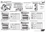
4. Note on insulation coordination according to AfK recommendation No. 5 (02/86)*The installation of the isolating spark gap at the insulating part requires coordination of itspower-frequency test voltage with the installation loop flown through by lightning currents.This results mainly from the configuration of cable length L and terminal height H via the pathSL of an insulating part to be bridged (see Figs. 3c, 3d). This prevents the voltage generatedin the installation loop H x L from causing a puncture or flashover at the insulation of theisolating point and thus causing the ignition of an electric arc or a permanent damage to theinsulation of the isolating point.The coordination values required for this purpose can be taken from the diagram (see page17) by transferring the values determined in the respective mounting situation for cable lengthL and terminal height H into the diagram and determining the resulting value for test voltagesU PW . This value corresponds to the power-frequency test voltage of the isolating point (e.g.of an insulating part) required for the respective configuration (effective value).This required power-frequency test voltage must be equal or less than the comparable valueindicated for the isolating point (e.g. 5 kV). If this condition is not fulfilled, an adaptation canbe performed by connecting further down conductors (isolating spark gaps). Here, the quantityof down conductors Z is increased until the value determined from their multiplication withthe indicated power-frequency test voltage of the isolating point is equal to or greater thanthe value for U PW from the diagram.U PW £ U N x ZU PW : Effective value of the power-frequency test voltage of the isolating point (kV) requiredfor a coordination.U N : Effective value of the nominal power-frequency test voltage of the isolating point (kV)Z: Quantity of parallel down conductors (isolating spark gaps) required for a coordination.Example:From a given type of installation, the following values are determined according to Fig 3c:L: 0.5 mH: 0.1 m Þ Diagram: U PW= 14,5 kVThe power-frequency test voltage U N indicated for the isolating point is 5 kVZ ³ U PW / U NZ ³ 14.5 kV / 5 kVZ = 316
<strong>100</strong>908017Test voltage U PW (kV)706050403020<strong>100</strong>0.1 0.2 0.3 0.5 0.75 1 1.5 2 2.5 3H = 0.2 mCable length L (m)H = 0.15 mH = 0.1 mH = 0.05 mH = 0.025 m
In the example described, a coordination of cable length L must therefore be established withthe nominal power-frequency test voltage of the insulating part with 3 parallel down conductors(isolating spark gaps).Note:For warranty reasons, the connecting cable (cable length, cross sectional area and connection)may be modified by the manufacturer only. Cable lengths which are longer than 0.3 m, arecustomised types (special lengths), which are prepared by the manufacturer according tocustomer specifications. The special lengths are marked with a corresponding sign whichindicates the cable length L.5. Maintenance and operationThe isolating spark gap is a maintenance-free device. An overload generally leads to awelding/short circuiting of the electrodes.If the system has a CP installation, the overload of the isolating spark gap is registered bythe potential indicator of the CP installation.A faulty isolating spark gap can also be detected by simple measuring of the resistance(measured value
Notes