AP04 - SIKO Products USA
AP04 - SIKO Products USA
AP04 - SIKO Products USA

Erfolgreiche ePaper selbst erstellen
Machen Sie aus Ihren PDF Publikationen ein blätterbares Flipbook mit unserer einzigartigen Google optimierten e-Paper Software.
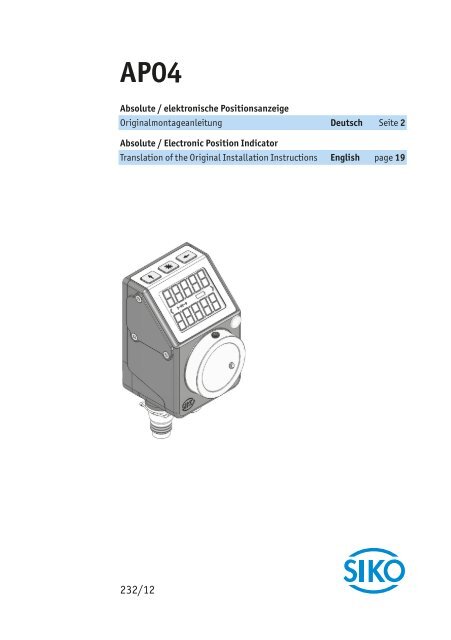
<strong>AP04</strong><br />
Absolute / elektronische Positionsanzeige<br />
Originalmontageanleitung Deutsch Seite 2<br />
Absolute / Electronic Position Indicator<br />
Translation of the Original Installation Instructions English page 19<br />
232/12
2<br />
<strong>AP04</strong><br />
Inhaltsverzeichnis<br />
<strong>AP04</strong> · Datum 19.07.2012 · Art. Nr. 84211 · Änd. Stand 232/12<br />
Deutsch<br />
1 Dokumentation . . . . . . . . . . . . . . . . . . . . 3<br />
2 Sicherheitshinweise . . . . . . . . . . . . . . . . . . 3<br />
2.1 Bestimmungsgemäße Verwendung . . . . . . . . . . . 3<br />
2.2 Kennzeichnung von Gefahren und Hinweisen . . . . . . . 3<br />
2.3 Zielgruppe . . . . . . . . . . . . . . . . . . . . . 4<br />
2.4 Grundlegende Sicherheitshinweise . . . . . . . . . . . 5<br />
3 Identifikation . . . . . . . . . . . . . . . . . . . . . 5<br />
4 Installation . . . . . . . . . . . . . . . . . . . . . . 5<br />
4.1 Mechanische Montage . . . . . . . . . . . . . . . . 5<br />
4.2 Elektrische Installation . . . . . . . . . . . . . . . 7<br />
5 Inbetriebnahme . . . . . . . . . . . . . . . . . . . 10<br />
6 Batteriewechsel . . . . . . . . . . . . . . . . . . . 13<br />
6.1 Art, Funktion und Lebensdauer der Batterie . . . . . . 14<br />
6.2 Betriebszustand . . . . . . . . . . . . . . . . . 14<br />
6.3 Austausch der Batterieeinheit . . . . . . . . . . . . 14<br />
6.4 Störung nach Batteriewechsel . . . . . . . . . . . . 15<br />
7 Transport, Lagerung, Wartung und Entsorgung . . . . . . 15<br />
8 Zubehör Anschluss-Stecker . . . . . . . . . . . . . . 16<br />
8.1 Gegenstecker M8 gerade . . . . . . . . . . . . . . 16<br />
8.2 Gegenstecker M8 BUS-Abschluss . . . . . . . . . . . 17<br />
8.3 Gegenstecker M8 gerade inkl. Kabel . . . . . . . . . 17<br />
9 Technische Daten . . . . . . . . . . . . . . . . . . 17
<strong>AP04</strong><br />
Dokumentation Deutsch<br />
GEFAHR<br />
1 Dokumentation<br />
Zu diesem Produkt gibt es folgende Dokumente:<br />
• Produkt-Datenblatt beschreibt die technischen Daten, die Abmaße,<br />
die Anschlussbelegungen, das Zubehör und den Bestellschlüssel.<br />
• Montageanleitung beschreibt die mechanische und die elektrische<br />
Montage mit allen sicherheitsrelevanten Bedingungen und der dazugehörigen<br />
technischen Vorgaben.<br />
• Benutzerhandbuch und Softwarebeschreibung zur Inbetriebnahme<br />
und zum Einbinden der Positionsanzeige in ein Feldbussystem.<br />
Diese Dokumente sind auch unter "http://www.siko.de/service/downloads/ausgewaehlte-downloads/details/ap04/"<br />
zu finden.<br />
2 Sicherheitshinweise<br />
2.1 Bestimmungsgemäße Verwendung<br />
Die absolute Positionsanzeige <strong>AP04</strong> dient für Verstell- und Positionieraufgaben<br />
an Anlagen und Maschinen. Die Positionsanzeige ist nur für die Verwendung<br />
im Industriebereich vorgesehen die keinen besonderen elektrischen<br />
oder mechanischen Sicherheitsanforderungen unterliegen.<br />
1. Beachten Sie alle Sicherheitshinweise in dieser Anleitung.<br />
2. Lesen Sie alle beigefügten Dokumentationen auf der CD.<br />
3. Eigenmächtige Umbauten und Veränderungen an der Positionsanzeige<br />
sind verboten.<br />
4. Die vorgeschriebenen Betriebs- und Installationsbedingungen sind<br />
einzuhalten.<br />
5. Die Positionsanzeige darf nur innerhalb der technischen Daten und der<br />
angegebenen Grenzen betrieben werden (siehe Kapitel 9).<br />
2.2 Kennzeichnung von Gefahren und Hinweisen<br />
Sicherheitshinweise bestehen aus dem Signalzeichen und einem Signalwort.<br />
Gefahrenklassen<br />
Unmittelbare Gefährdungen die zu schweren irreversiblen Körperverletzungen<br />
mit Todesfolge, Sachschäden oder ungeplanten Gerätereaktionen<br />
führen können, sofern Sie die gegebenen Anweisungen missachten.<br />
<strong>AP04</strong> · Datum 19.07.2012 · Art. Nr. 84211 · Änd. Stand 232/12<br />
3
4<br />
<strong>AP04</strong><br />
Sicherheitshinweise Deutsch<br />
WARNUNG<br />
VORSICHT<br />
ACHTUNG<br />
WARNUNG<br />
Gefährdungen die zu schweren Körperverletzungen, Sachschäden oder<br />
ungeplanten Gerätereaktionen führen können, sofern Sie die gegebenen<br />
Anweisungen missachten.<br />
Gefährdungen die zu leichten Verletzungen, Sachschäden oder ungeplanten<br />
Gerätereaktionen führen können, sofern Sie die gegebenen Anweisungen<br />
missachten.<br />
Wichtige Betriebshinweise welche die Bedienung erleichtern oder die bei<br />
Nichtbeachtung zu ungeplanten Gerätereaktionen führen können und<br />
somit möglicherweise zu Sachschäden führen können.<br />
Signalzeichen<br />
2.3 Zielgruppe<br />
Montageanleitung und Benutzerhandbuch wenden sich an das Projektierungs-,<br />
Inbetriebnahme- und Montagepersonal von Anlagen- oder<br />
Maschinenherstellern. Dieser Personenkreis benötigt fundierte Kenntnisse<br />
über die notwendigen Anschlüsse einer Positionsanzeige und dessen Integration<br />
in die komplette Maschinenanlage.<br />
Nicht ausreichend qualifiziertes Personal<br />
Personenschäden, schwere Schäden an Maschine und Positionsanzeigen<br />
werden durch nicht ausreichend qualifiziertes Personal verursacht.<br />
` Projektierung, Inbetriebnahme, Montage und Wartung nur durch<br />
geschultes Fachpersonal.<br />
` Dieses Personal muss in der Lage sein, Gefahren, welche durch die<br />
mechanische, elektrische oder elektronische Ausrüstung verursacht<br />
werden können, zu erkennen.<br />
Qualifiziertes Personal<br />
sind Personen, die<br />
• als Projektierungspersonal mit den Sicherheitsrichtlinien der Elektro-<br />
und Automatisierungstechnik vertraut sind;<br />
• als Inbetriebnahme und Monatagepersonal berechtigt sind, Stromkreise<br />
und Geräte/Systeme gemäß den Standards der Sicherheitstechnik<br />
in Betrieb zu nehmen, zu erden und zu kennzeichnen.<br />
<strong>AP04</strong> · Datum 19.07.2012 · Art. Nr. 84211 · Änd. Stand 232/12
<strong>AP04</strong><br />
Identifikation Deutsch<br />
GEFAHR<br />
WARNUNG<br />
VORSICHT<br />
VORSICHT<br />
2.4 Grundlegende Sicherheitshinweise<br />
Explosionsgefahr<br />
` Positionsanzeige nicht in explosionsgefährdeten Zonen einsetzen.<br />
Rotierende Teile<br />
Quetschungen, Reibung, Abschürfen, Erfassen von Gliedmaßen und Kleidung<br />
durch Berühren von rotierende Teile wie z. B. Klemmring, Drehmomentstütze<br />
oder Hohlwelle im Betrieb.<br />
` Zugriffsmöglichkeit durch Schutzmaßnahmen verhindern.<br />
Externe Magnetfelder<br />
Es kommt zu Betriebsstörungen und Datenverlust, wenn starke externe<br />
Magnetfelder das interne Messsystem beeinflussen.<br />
` Schützen Sie die Positionsanzeige vor Einflüssen von Fremdmagneten.<br />
3 Identifikation<br />
Das Typenschild zeigt den Gerätetyp mit Variantennummer. Die Lieferpapiere<br />
ordnen jeder Variantennummer eine detaillierte Bestellbezeichnung<br />
zu.<br />
z. B. <strong>AP04</strong>-0023<br />
4 Installation<br />
Varianten-Nr.<br />
Geräte-Typ<br />
4.1 Mechanische Montage<br />
Zerstörung Hauptlager<br />
Unsachgemäße Montage (z. B. Spannungen an der Antriebswelle) führt zu<br />
zusätzlicher Belastung sowieErwärmung und langfristig zur Zerstörung<br />
der Positionsanzeige.<br />
` Sorgen Sie für einen geringen Wellen- und Winkelversatz zwischen<br />
Welle und Aufnahmebohrungen durch geeignete Fertigungsmaßnahmen<br />
(siehe Abb. 1 + Tab. 1).<br />
<strong>AP04</strong> · Datum 19.07.2012 · Art. Nr. 84211 · Änd. Stand 232/12<br />
5
6<br />
<strong>AP04</strong><br />
Installation Deutsch<br />
VORSICHT<br />
ACHTUNG<br />
Ausfall Positionsanzeige<br />
` IP-Schutzart bei Montage beachten (siehe Kapitel 9), bei Bedarf<br />
schützen.<br />
` Schutzartbedingt beide Gegenstecker (siehe Kapitel 8) mit mind. 1 Nm<br />
an die Positionsanzeige schrauben.<br />
` Positionsanzeige nicht selbst öffnen (Ausnahme siehe Kapitel 6).<br />
` Schläge auf das Gerät vermeiden.<br />
` Keinerlei Veränderung am Gerät vornehmen.<br />
Verlust der Schutzart<br />
Bei Betrieb mit offenem Anschluss geht die Schutzart verloren.<br />
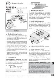
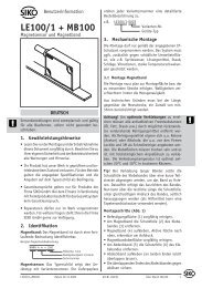
Vorbereitung Montage (Abb. 1, Abb. 2, Abb. 3):<br />
1. Beiliegende selbstklebende Dichtungsplatte 1 (Moosgummi) auf<br />
Lagerbügel bzw. Zwischenplatte aufkleben (Sicherstellung der Schutzart,<br />
ausgleichen von Unebenheiten).<br />
2. Bohrung (ød) für Drehmomentstütze 2 auf Abstand (L1) zur<br />
Antriebswelle 3 fertigen.<br />
3. Durchmesser (øD) der Antriebswelle 3 beachten.<br />
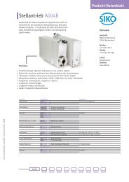
Montage (Abb. 1, Abb. 2, Abb. 3):<br />
1. Positionsanzeige inkl. Dichtungsplatte bis Anschlag auf Welle 3<br />
schieben. Drehmomentstütze 2 in vorhandene Bohrung einführen<br />
(verspannungsfreie Montage). Eine Langloch für die Drehmomentstütze<br />
wird empfohlen.<br />
2. Gewindestifte M3 4 mit maximal 0,2 Nm anziehen.<br />
� ��<br />
� ��<br />
�<br />
Abb. 1: Einbaumaße<br />
�<br />
<strong>AP04</strong> · Datum 19.07.2012 · Art. Nr. 84211 · Änd. Stand 232/12<br />
����<br />
Maß ød ø6 (Form A)<br />
ø10 +0.8 (Form B)<br />
Maß L1 22<br />
Maß øD ø20 (Spielpassung)<br />
Tab. 1: Einbaumaße
<strong>AP04</strong><br />
Installation Deutsch<br />
WARNUNG<br />
WARNUNG<br />
WARNUNG<br />
�<br />
Abb. 2: Montage<br />
4.2 Elektrische Installation<br />
Abb. 3: Anzugsmoment<br />
Gewindestift<br />
<strong>AP04</strong> · Datum 19.07.2012 · Art. Nr. 84211 · Änd. Stand 232/12<br />
�<br />
1 Dichtungsplatte<br />
2 Drehmomentstütze<br />
3 Welle<br />
4 Gewindestift<br />
Zerstörung von Anlagenteilen und Verlust der Steuerungskontrolle<br />
` Alle Leitungen für die Positionsanzeige müssen geschirmt sein.<br />
` Anschlussverbindungen nicht unter Spannung schließen oder lösen.<br />
` Verdrahtungsarbeiten spannungslos durchführen.<br />
` Litzen mit geeigneten Aderendhülsen versehen.<br />
` Vor dem Einschalten sind alle Leitungsanschlüsse und Steckverbindungen<br />
zu überprüfen.<br />
Unvorhergesehene Geräteaktionen der Positionsanzeige oder anderer<br />
Geräte<br />
Die Positionsanzeige ist gegen EMV Ein- und Ausstrahlung (Elektromagnetische<br />
Verträglichkeit) geschützt. Zu starke externe EMV Strahlung kann<br />
zu unvorhergesehene Aktionen der Positionsanzeige führen (z. B. Zerstörung<br />
der Positionsanzeige; Positionswertverlust).<br />
` Führen Sie die Verdrahtung gemäß den EMV-Maßnahmen IEC 61326-1<br />
und Kapitel 4.2 durch.<br />
` Überprüfen Sie die korrekte Ausführung der EMV-Maßnahmen.<br />
Brandgefahr<br />
Zum Schutz von Folgeschäden bei Gerätedefekten wird eine Absicherung<br />
empfohlen.<br />
` Die Nennstromstärke einer trägen Sicherung muss der Geräteanzahl<br />
im System entsprechend angepasst sein (siehe Kapitel 9).<br />
7
8<br />
<strong>AP04</strong><br />
Installation Deutsch<br />
Alle Anschlüsse sind prinzipiell gegen äußere Störeinflüsse geschützt. Der<br />
Einsatzort ist so zu wählen, dass induktive oder kapazitive Störungen nicht<br />
auf die Positionsanzeige oder deren Anschlussleitungen einwirken können.<br />
Das System in möglichst großem Abstand von Leitungen einbauen,<br />
die mit Störungen belastet sind. Gegebenenfalls sind zusätzliche Maßnahmen,<br />
wie Schirmbleche oder metallisierte Gehäuse vorzusehen. Schützspulen<br />
müssen mit Funkenlöschgliedern beschaltet sein.<br />
Anschlusskonzept<br />
Werden mehrere Positionsanzeigen gemeinsam betrieben, müssen diese<br />
an ein gemeinsames GND-Potential angeschlossen werden. Das Signal GND<br />
ist hierzu stets in der Busverdrahtung mitzuführen.<br />
Kontakte, die eine Spannung führen können, müssen gegen Berührung<br />
geschützt sein. Daher ist darauf zu achten, dass der Anschluss der Positionsanzeige<br />
über den Anschluss "Bus EIN" erfolgt (siehe Abb. 4). Dadurch<br />
sind die spannungsführenden Kontakte an "Bus AUS" durch die Buchse<br />
geschützt (zur IP-Schutzart siehe Kapitel 4.1).<br />
Für die Funktion des Feldbusses ist ein Abschlusswiderstand notwendig<br />
(120 Ohm). Dieser muss am letzten Busteilnehmer zwischen DÜA/TxRx+<br />
und DÜB/TxRx- eingesetzt werden.<br />
Zulässige Leistungsaufnahme<br />
Die Versorgung für die Positionsanzeige ist ausreichend zu dimensionieren.<br />
Die Stromaufnahme ist im Einschaltaugenblick kurzzeitig höher als<br />
der Nennstrom. Die Versorgungswerte sind den technischen Daten in Kapitel<br />
9 zu entnehmen.<br />
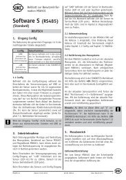
Anschlussbelegung Schnittstelle RS485<br />
• 1 Bus EIN: Stift 4 pol. (siehe Abb. 4).<br />
• 2 Bus AUS: Buchse 4 pol. (siehe Abb. 4).<br />
Zubehör Gegenstecker und Kabelverlängerungen siehe Kapitel 8.<br />
PIN Belegung<br />
1 DÜB/TxRx-/CANL<br />
2 DÜA/TxRx+/CANH<br />
3 +UB<br />
4 GND<br />
<strong>AP04</strong> · Datum 19.07.2012 · Art. Nr. 84211 · Änd. Stand 232/12<br />
Bus-Ein<br />
� �<br />
Bus-Aus<br />
� �<br />
�<br />
� �<br />
�<br />
Ansichtseite = Steckseite
<strong>AP04</strong><br />
Installation Deutsch<br />
� �<br />
Abb. 4: Anschlussbelegung<br />
Datenübertragung Schnittstelle RS485<br />
RS482 Baudrate max. Busnetzlänge<br />
115.2 kbit/s 200 m<br />
57.6 kbit/s 400 m<br />
19.6 kbit/s 1200 m<br />
Datenübertragung Schnittstelle CAN<br />
CAN Baudrate max. Busnetzlänge<br />
125 kbit/s 320 m<br />
250 bit/s 160 m<br />
500 bit/s 80 m<br />
1 Mbit/s 40 m<br />
Litzenquerschnitt Leitungen min. 0,14 mm²-max. 0,5 mm².<br />
Anschluss Erdung (PE)<br />
<strong>AP04</strong> · Datum 19.07.2012 · Art. Nr. 84211 · Änd. Stand 232/12<br />
�<br />
1 Bus EIN<br />
2 Bus AUS<br />
3 PE Anschluss<br />
Zum Schutz vor Störungen müssen die Schirme der Signalleitungen und<br />
Netzleitung beidseitig angeschlossen werden. Potentialunterschiede führen<br />
zu unzulässigen Strömen auf dem Schirm. Den PE Anschluss 3 zwischen<br />
den Anschlusssteckern auf das Schutzleiterpotential legen (siehe<br />
Abb. 4). Verwenden Sie dazu 6,3 mm Flachstecker mit kurzer Litze 2,5 mm²<br />
… 4 mm² (nicht im Lieferumfang). Bei mehreren Positionsanzeigen wird<br />
empfohlen die Erdung auf eine PE-Schiene 1 anzuschließen (siehe Abb.<br />
5).<br />
9
10<br />
<strong>AP04</strong><br />
Inbetriebnahme Deutsch<br />
Abb. 5: PE-Schiene<br />
5 Inbetriebnahme<br />
Anzeige und Bedientasten<br />
Die Positionsanzeige verfügt über eine zweizeilige Anzeige mit Sonderzeichen<br />
und drei Bedientasten. Über die Tasten wird die Positionsanzeige<br />
parametriert und gesteuert. Eine LED 1 dient der Positionierüberwachung.<br />
Im Grundzustand (Werkseinstellung) wird in der 1. Zeile der Istwert<br />
und in der 2. Zeile der Sollwert dargestellt. Bei kritischem Batteriezustand<br />
blinkt das Sonderzeichen , bei leerer Batterie leuchtet<br />
dauerhaft. Bei eingeschaltetem Kettenmaß wird das Kettenmaßsymbol<br />
eingeblendet.<br />
Abb. 6: Bedienelemente<br />
<strong>AP04</strong> · Datum 19.07.2012 · Art. Nr. 84211 · Änd. Stand 232/12<br />
�<br />
�
<strong>AP04</strong><br />
Inbetriebnahme Deutsch<br />
Manueller Einrichtbetrieb<br />
Nach Anlegen der Versorgungsspannung (siehe Kapitel 4.2) befindet sich<br />
die Positionsanzeige auf der obersten Ebene der Menüstruktur (Default/<br />
Auslieferungszustand).<br />
• Das Drücken der - Taste schaltet die Kettenmaß-Funktion ein- bzw.<br />
aus.<br />
• Das Drücken der - Taste startet die Kalibrierung (siehe Benutzerhandbuch).<br />
• Das Drücken der - Taste startet den Parametrier-/Programmiermodus<br />
(siehe Benutzerhandbuch).<br />
LED-Anzeigen<br />
Im Grundzustand (Werkseinstellung) hat die LED-Anzeige folgende Bedeutung.<br />
Farbe Zustand Beschreibung<br />
grün ein Aktueller Positionswert befindet sich innerhalb des<br />
programmierten Positionsfensters.<br />
aus Aktueller Positionswert befindet sich außerhalb des<br />
programmierten Positionsfensters.<br />
rot ein Aktueller Positionswert befindet sich innerhalb des<br />
programmierten Positionsfensters.<br />
aus Aktueller Positionswert befindet sich innerhalb des<br />
programmierten Positionsfensters.<br />
Konfiguration<br />
(nur bei CAN + RS485/<strong>SIKO</strong>NETZ3,4)<br />
Im Konfigurations-Modus werden die erforderlichen Parameter eingestellt.<br />
Hierbei wird im Display in der 1. Zeile jeweils der Parameter und in<br />
der 2. Zeile der zugehörige Wert dargestellt.<br />
Mit der -Taste kann der aktuelle Wert, bei mehrstelligen Zahlen an der<br />
blinkenden Stelle bzw. komplett (z. B. "e" -> "dir") verändert werden.<br />
Mit der -Taste wird bei mehrstelligen Zahlen zur nächsten Stelle weitergeschaltet.<br />
Durch betätigen der -Taste wird der eingestellte Wert bestätigt und<br />
nichtflüchtig gespeichert. Wird keine Taste betätigt, so wird der Konfigurations-Modus<br />
nach ca. 30 s verlassen, ohne dass der zuletzt angezeigte<br />
Wert gespeichert wird, d. h. der ursprüngliche Wert bleibt erhalten.<br />
<strong>AP04</strong> · Datum 19.07.2012 · Art. Nr. 84211 · Änd. Stand 232/12<br />
11
12<br />
<strong>AP04</strong><br />
Inbetriebnahme Deutsch<br />
Konfigurationsparameter<br />
(nur bei CAN + RS485/<strong>SIKO</strong>NETZ3,4; RS485/<strong>SIKO</strong>NETZ5 siehe Benutzerhandbuch)<br />
Parameter Wertebereich Default Bedeutung/Bemerkung<br />
Id 1 ... 127 1 Bus-Adresse<br />
RS485:<br />
SnEt<br />
CAN: bAUd<br />
3, 4<br />
ACHTUNG<br />
<strong>AP04</strong> · Datum 19.07.2012 · Art. Nr. 84211 · Änd. Stand 232/12<br />
4<br />
Nach Änderung des Parameters<br />
muss ein Neustart durchgeführt<br />
werden!<br />
<strong>SIKO</strong>NETZ Kommunikationsprotokoll<br />
CAN Baudrate (z. B. 250<br />
kbit/s)<br />
125, 250, 500,<br />
1000kbd<br />
250<br />
APU 0 ... 59999 720 Anzeige pro Umdrehung<br />
dIV 1, 10, 100, 1000 1 Anzeigendivisor<br />
dIr I, E E Drehrichtung im bzw. entgegen<br />
dem Uhrzeigersinn<br />
dEZ 0, 0.0, 0.00,<br />
0.000, 0.0000<br />
0.0 Anzeige Nachkommastellen<br />
OFFSt -9999 ... +9999 0 Offset-Wert<br />
CAL -9999 ... +9999 0 Kalibrierwert<br />
F0SEt 0, 1 1 Freigabe Nullung<br />
FCEtt 0, 1 1 Freigabe Kettenmaß<br />
InPOS 0 ... +9999 5 Abweichungsfenster von Sollzu<br />
Istwert<br />
Loop 0 ... +9999 0 Schleifenumkehrpunkt (in<br />
Anzeigeeinheit)<br />
LPdIr dIr, I, E dIr Positioniereinrichtung für<br />
Schleife<br />
GrEEn 0 (AUS), 1 (EIN) 1 grüne LED leuchtet wenn Zielfenster<br />
erreicht 1)<br />
rEd 0 (AUS), 1 (EIN) 1 rote LED leuchtet bei Position<br />
außerhalb des Zielfensters 1)<br />
FLASh 0 (AUS), 1 (EIN) 0 LED blinkt wenn eingeschaltet<br />
CodE 0 ... 99999 0 Für Prüfzwecke/Diagnose<br />
00100<br />
Abgleichfahrt<br />
11100<br />
2)<br />
Werkseinstellungen laden<br />
dISPL 0, 180 0 Display-Orientierung<br />
1) Direktzugriff auf LEDs via <strong>SIKO</strong>NETZ3/CAN, wenn beide hier genannten<br />
LED-Funktionen AUS.
<strong>AP04</strong><br />
Batteriewechsel Deutsch<br />
GEFAHR<br />
VORSICHT<br />
VORSICHT<br />
2) Abgleichfahrt<br />
Die <strong>AP04</strong> ist bei Auslieferung voll Funktionsfähig und es ist keine<br />
Abgleichfahrt notwendig. Bei einem gleichzeitigen Ausfall der Batterieversorgung<br />
und der Versorgungsspannung (z. B. bei Batteriewechsel)<br />
kann der absolute Positionswert verloren gehen. Um die Funktionsfähigkeit<br />
dann wieder herzustellen ist eine Nullung durchzuführen.<br />
Soll dennoch eine Abgleichfahrt vorgenommen werden, muss wie folgt<br />
vorgegangen werden: Durch die Eingabe des CODE 00100 wird, nach Bestätigung<br />
der Displayrichtung die <strong>AP04</strong> in den Abgleichmodus gebracht.<br />
Display: 1. Zeile "AbGL_"<br />
2. Zeile "_XXX" wobei XXX einen Wert um 100 zeigt.<br />
Die <strong>AP04</strong> Welle muss nun entgegen dem Uhrzeigersinn um wenige mm, mit<br />
einer Geschwindigkeit
14<br />
<strong>AP04</strong><br />
Batteriewechsel Deutsch<br />
VORSICHT<br />
6.1 Art, Funktion und Lebensdauer der Batterie<br />
• Batterieeinheit Bestellnummer <strong>SIKO</strong>: Art.Nr. "84208".<br />
Die Batterie ermöglicht die Erkennung und Speicherung stromloser Verstellungen<br />
der Welle. Je nach Umgebungsbedingungen und Einschaltdauer<br />
der Versorgungsspannung der Positionsanzeige beträgt die Batterielebensdauer<br />
im Mittel ca. 5 Jahre. Der Austausch kann bei <strong>SIKO</strong>-Vertriebspartnern,<br />
im <strong>SIKO</strong>-Stammwerk oder selbst durchgeführt werden.<br />
6.2 Betriebszustand<br />
Batteriesymbol blinkt: Batterie nahezu leer<br />
Batteriesymbol leuchtet: Batterie erneuern<br />
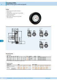
6.3 Austausch der Batterieeinheit<br />
Ausfall Positionsanzeige<br />
Unsachgemäße Montage führt zum Verlust der Schutzart.<br />
` Schrauben 1 gleichmäßig anziehen bis Batterieeinheit 2 vollständig<br />
auf Anschlag mit Gehäuse 4 ist.<br />
Vorbereitung:<br />
1. Positionsanzeige an Versorgungsspannung anschließen.<br />
2. Austauschbatterieeinheit bereitlegen (siehe Kapitel 6.1).<br />
3. Kreuzschlitzschraubendreher (z. B. PH 0x60) bereitlegen.<br />
Demontage (siehe Abb. 7):<br />
1. Das Batteriefach befindet sich auf der linken Seite des Gerätes<br />
(Anschlüsse unten).<br />
2. 3 Befestigungsschrauben 1 herausdrehen.<br />
3. Batterieeinheit 2 herausnehmen (Entsorgung der Altbatterie siehe<br />
Kapitel 6).<br />
Montage (siehe Abb. 7):<br />
1. Neue Batterieeinheit 2 einbauen. Auf leichte Fügbarkeit achten.<br />
2. Korrekte Lage des O-Rings 3 überprüfen. O-Ring muss bei der Montage<br />
am Batteriegehäuse aufliegen.<br />
<strong>AP04</strong> · Datum 19.07.2012 · Art. Nr. 84211 · Änd. Stand 232/12
<strong>AP04</strong><br />
Transport, Lagerung, Wartung und Entsorgung Deutsch<br />
ACHTUNG<br />
�<br />
�<br />
�<br />
Abb. 7: Batteriewechsel<br />
6.4 Störung nach Batteriewechsel<br />
Datenverlust<br />
Batteriesymbol im Display leuchtet trotz neuer Batterie.<br />
` Unzureichende Kontaktierung, Kapitel 6.3 wiederholen.<br />
<strong>AP04</strong> · Datum 19.07.2012 · Art. Nr. 84211 · Änd. Stand 232/12<br />
�<br />
1 Schrauben<br />
2 Batterieeinheit<br />
3 O-Ring<br />
4 Gehäuse<br />
` Positionsanzeige von der Versorgungsspannung trennen. Bei erneutem<br />
Anlegen der Versorgungsspannung wird die Batterieanzeige initialisiert<br />
und aktualisiert. Kalibrierfahrt nach Benutzerhandbuch vornehmen.<br />
7 Transport, Lagerung, Wartung und Entsorgung<br />
Transport und Lagerung<br />
Positionsanzeigen sorgfältig behandeln, transportieren und lagern.<br />
Hierzu sind folgende Punkte zu beachten:<br />
• Positionsanzeigen in der ungeöffneten Originalverpackung transportieren<br />
und/oder lagern.<br />
• Positionsanzeigen vor schädlichen physikalischen Einflüssen wie<br />
Staub, Hitze und Feuchtigkeit schützen.<br />
• Anschlüsse weder durch mechanische noch durch thermische Einflüsse<br />
beschädigen.<br />
• Vor Montage ist die Positionsanzeige auf Transportschäden zu untersuchen.<br />
Beschädigte Positionsanzeigen nicht einbauen.<br />
15
16<br />
<strong>AP04</strong><br />
Zubehör Anschluss-Stecker Deutsch<br />
ACHTUNG<br />
Wartung<br />
Bei korrektem Einbau nach Kapitel 4 ist die Positionsanzeige, bis auf einen<br />
eventuellen Batteriewechsel nach Kapitel 6, wartungsfrei. Die Positionsanzeige<br />
enthält eine Lebensdauerschmierung und muss unter normalen<br />
Betriebsbedingungen nicht nachgeschmiert werden.<br />
Entsorgung<br />
Die elektronischen Bauteile der Positionsanzeige enthalten umweltschädigende<br />
Stoffe und sind zugleich Wertstoffträger. Die Positionsanzeige<br />
muss deshalb nach ihrer endgültigen Stilllegung einem Recycling zugeführt<br />
werden. Die Umweltrichtlinien des jeweiligen Landes müssen hierzu<br />
beachtet werden.<br />
Batterie: Werfen Sie Batterien nicht in den normalen Müll, ins Feuer oder<br />
ins Wasser. Batterien sollen gesammelt und auf umweltfreundliche Weise<br />
entsorgt werden.<br />
Nur für EU-Länder: Gemäß der Richtlinie 91/157/EWG müssen defekte<br />
oder verbrauchte Batterien recycelt werden.<br />
8 Zubehör Anschluss-Stecker<br />
(nicht im Lieferumfang enthalten)<br />
8.1 Gegenstecker M8 gerade<br />
• Zubehör <strong>SIKO</strong> Art.Nr. "84209" (Buchse 4 pol. Bus EIN).<br />
• Zubehör <strong>SIKO</strong> Art.Nr. "84210" (Stift 4 pol. Bus AUS).<br />
Empfehlung<br />
` Litzenquerschnitt Leitungen min. 0,14 mm² - max. 0,25 mm² / Kabeldurchlass:<br />
ø3,5-ø5 mm.<br />
Montage (Abb. 8)<br />
1. Teile 1 ... 4 über Kabelmantel schieben.<br />
2. Kabel abmanteln.<br />
3. Schirm kürzen, aufweiten und um Schirmring 4 legen.<br />
4. Litzen durch Kupplungshülse 5 fädeln und abisolieren.<br />
5. Teile 2 ... 4 montieren. Druckschraube 1 andrehen um das Kabel<br />
zu fixieren.<br />
6. Isolierschlauch 6 auffädeln, Litzen anlöten und Isolierschlauch montieren.<br />
<strong>AP04</strong> · Datum 19.07.2012 · Art. Nr. 84211 · Änd. Stand 232/12
<strong>AP04</strong><br />
Technische Daten Deutsch<br />
7. Kupplungshülse 5 mit Einsatz 7 verschrauben und Druckschraube<br />
1 festdrehen.<br />
�<br />
�<br />
��<br />
�<br />
�<br />
Abb. 8: Gegenstecker M8 gerade<br />
�<br />
8.2 Gegenstecker M8 BUS-Abschluss<br />
<strong>AP04</strong> · Datum 19.07.2012 · Art. Nr. 84211 · Änd. Stand 232/12<br />
�<br />
�<br />
Für die Funktion des Feldbusses ist ein Abschlusswiderstand notwendig<br />
(120 Ohm).<br />
• Zubehör <strong>SIKO</strong> Art. Nr. "BAS-0005" (Stift 4 pol.).<br />
Bei mehreren Positionsanzeigen an einem Bus: Abschlussstecker am letzten<br />
Busteilnehmer an Bus AUS anschließen (siehe Kapitel 4.2).<br />
Bei einer Positionsanzeige: Abschlussstecker an Bus AUS anschließen<br />
(siehe Kapitel 4.2).<br />
8.3 Gegenstecker M8 gerade inkl. Kabel<br />
• Zubehör <strong>SIKO</strong> Art. Nr. "KV04S1" (Stift/Buchse 4 pol. Bus EIN/Bus<br />
AUS).<br />
9 Technische Daten<br />
Mechanische Daten Ergänzung<br />
Gehäusematerial Kunststoff verstärkt Steckergewinde Metall<br />
Antriebswelle nichtrostender Stahl<br />
Gehäusefarbe schwarz, RAL 9005<br />
max. Drehzahl ≤ 500 min -1<br />
�<br />
�<br />
17
18<br />
<strong>AP04</strong><br />
Technische Daten Deutsch<br />
Elektrische Daten Ergänzung<br />
Betriebsspannung 24 VDC ±20 %<br />
Stromaufnahme ca. 20 mA bei Betrieb mit LEDs zzgl. ca.<br />
3 mA pro LED<br />
Batterielebensdauer ca. 5 Jahre<br />
Anschlussart 2 x M8-Steckverbinder 4 polig, 1x Buchse, 1x Stecker,<br />
zusätzlicher Schirmanschluss<br />
über Flachstecker 6,3 mm<br />
Busanschluss CAN-Bus oder RS485 keine galvanische Trennung<br />
Anzeige LCD 7-Segment + Dezimalpunkte; 2<br />
Zeilen a 5 Stellen, Sonderzeichen<br />
Sonderzeichen Pfeil links, Pfeil rechts, Kettenmaß,<br />
Batterie<br />
Anzeigengrösse ca. 7 mm Ziffernhöhe<br />
Signalanzeige zweifarbige LED (rot / grün) Positionsstatus, parametrierbar<br />
Tasten Kettenmaßfunktion, Parametrieren,<br />
Rücksetzen<br />
Abtastung Magnetisch<br />
Auflösung 720 Inkremente / Umdrehung<br />
Anzeigenauflösung frei parametrierbar zwischen<br />
1 und 65535 Inkremente /<br />
Umdrehung<br />
Max. codierte Anzahl<br />
Umdrehungen<br />
max. 7281 Umdrehungen<br />
Umgebungsbedingungen Ergänzung<br />
Temperaturbereich<br />
Betrieb<br />
0°… +60 °C<br />
Temperaturbereich Lagerung<br />
-20 °C … +80 °C<br />
Luftfeuchtigkeit Betauung nicht zulässig<br />
Prüfzeichen / Störschutzklasse<br />
CE-konform gemäß EN 61326-1 Klasse A<br />
Schutzart IP53<br />
im angebauten Zustand; Standardversion<br />
(bei montierten<br />
Gegensteckern)<br />
IP65<br />
optional (bei montierten Gegensteckern)<br />
<strong>AP04</strong> · Datum 19.07.2012 · Art. Nr. 84211 · Änd. Stand 232/12
<strong>AP04</strong><br />
Table of contents<br />
<strong>AP04</strong> · Date 19.07.2012 · Art. No. 84211 · Mod. status 232/12<br />
English<br />
1 Documentation . . . . . . . . . . . . . . . . . . . 20<br />
2 Safety information . . . . . . . . . . . . . . . . . . 20<br />
2.1 Intended use . . . . . . . . . . . . . . . . . . . 20<br />
2.2 Identification of dangers and notes . . . . . . . . . . 20<br />
2.3 Target group . . . . . . . . . . . . . . . . . . . 21<br />
2.4 Basic safety information . . . . . . . . . . . . . . 21<br />
3 Identification . . . . . . . . . . . . . . . . . . . . 22<br />
4 Installation . . . . . . . . . . . . . . . . . . . . . 22<br />
4.1 Mechanical mounting . . . . . . . . . . . . . . . 22<br />
4.2 Electrical Installation . . . . . . . . . . . . . . . 24<br />
5 Commissioning . . . . . . . . . . . . . . . . . . . 26<br />
6 Battery change . . . . . . . . . . . . . . . . . . . 30<br />
6.1 Battery, function and service life . . . . . . . . . . . 30<br />
6.2 Operating states . . . . . . . . . . . . . . . . . 30<br />
6.3 Changing the battery unit . . . . . . . . . . . . . 30<br />
6.4 Faults after battery change . . . . . . . . . . . . . 31<br />
7 Transport, Storage, Maintenance and Disposal . . . . . . 32<br />
8 Accessory connector . . . . . . . . . . . . . . . . . 32<br />
8.1 Straight matting connector M8 . . . . . . . . . . . 32<br />
8.2 Mating connector M8 bus terminator . . . . . . . . . 33<br />
8.3 Mating connector M8 straight inclusive cable . . . . . . 33<br />
9 Technical data . . . . . . . . . . . . . . . . . . . . 34<br />
19
20<br />
<strong>AP04</strong><br />
Documentation English<br />
DANGER<br />
WARNING<br />
1 Documentation<br />
The following documents describe this product:<br />
• The product data sheet describes the technical data, the dimensions,<br />
the pin assignments, the accessories and the order key.<br />
• The mounting instructions describe the mechanical and electrical installation<br />
including all safety-relevant requirements and the associated<br />
technical specifications.<br />
• The user manual and software description for commissioning and integrating<br />
the position indicator into a fieldbus system.<br />
These documents can also be downloaded at "http://www.siko.de/en/<br />
service/downloads/selected-downloads/details/ap04/".<br />
2 Safety information<br />
2.1 Intended use<br />
The Ap04 position indicator serves for adjustment and positioning tasks<br />
on plants and machines. The position indicator is only intended for use in<br />
industrial applications that are not subject to special electrical or mechanical<br />
safety requirements.<br />
1. Observe all safety instructions contained herein.<br />
2. Read all documents provided on the CD.<br />
3. Arbitrary modifications and changes to this position indicator are forbidden.<br />
4. Observe the prescribed operating and installation conditions.<br />
5. Operate the position indicator exclusively within the technical data<br />
and the specified limits (see chapter 9).<br />
2.2 Identification of dangers and notes<br />
Safety notes consist of a signal sign and a signal word.<br />
Danger classes<br />
Immediate danger that may cause irreversible bodily harm resulting in<br />
death, property damage or unplanned device reactions if you disregard<br />
the instructions given.<br />
Danger that may cause serious bodily harm, property damage or unplanned<br />
device reactions if you disregard the instructions given.<br />
<strong>AP04</strong> · Date 19.07.2012 · Art. No. 84211 · Mod. status 232/12
<strong>AP04</strong><br />
Safety information English<br />
CAUTION<br />
NOTICE<br />
WARNING<br />
DANGER<br />
WARNING<br />
Danger that may cause minor injury, property damage or unplanned device<br />
reactions if you disregard the instructions given.<br />
Important operating information that may facilitate operation or cause<br />
unplanned device reactions if disregarded including possible property<br />
damage.<br />
Signal signs<br />
2.3 Target group<br />
Installation instructions and User manual are intended for the configuration,<br />
commissioning and mounting personnel of plant or machine manufacturers.<br />
This group needs profound knowledge of an position indicator's<br />
necessary connections and its integration into a complete machinery.<br />
Insufficiently qualified personnel<br />
Insufficiently qualified personnel cause personal injury, serious damage to<br />
machinery or position indicator.<br />
` Configuration, commissioning, mounting and maintenance by trained<br />
expert personnel only.<br />
` This personnel must be able to recognize danger that might arise from<br />
mechanical, electrical or electronic equipment.<br />
Qualified personnel are persons who<br />
• are familiar with the safety guidelines of the electrical and automation<br />
technologies when performing configuration tasks;<br />
• are authorized to commission, earth and label circuits and devices/<br />
systems in accordance with the safety standards.<br />
2.4 Basic safety information<br />
Danger of explosion<br />
` Do not use the position indicator in explosive zones.<br />
Rotating parts<br />
Bruising, rubbing, abrasing, seizing of extremities or clothes by touching<br />
during operation any rotating parts as for example clamping ring, torque<br />
support or hollow shaft.<br />
` Prevent people from access by installing protective facilities.<br />
<strong>AP04</strong> · Date 19.07.2012 · Art. No. 84211 · Mod. status 232/12<br />
21
22<br />
<strong>AP04</strong><br />
Identification English<br />
CAUTION<br />
CAUTION<br />
CAUTION<br />
NOTICE<br />
External magnetic fields<br />
Failures and data loss occur if strong magnetic fields influence the internal<br />
measuring system.<br />
` Protect the position indicator from impact by external magnets.<br />
3 Identification<br />
Please check the particular type of unit and type number from the identification<br />
plate. Type number and the corresponding version are indicated in<br />
the delivery documentation.<br />
e. g. <strong>AP04</strong>-0023<br />
4 Installation<br />
version number<br />
type of unit<br />
4.1 Mechanical mounting<br />
Destruction of main bearings<br />
Improper installation (e. g. tension on the driving shaft) causes additional<br />
heat development and destruction of the position indicator in the long<br />
term.<br />
` Ensure a low shaft and angle offset between shaft and accommodation<br />
bore by applying appropriate manufacturing methods (see Fig. 1<br />
+ Tab. 1).<br />
Position indicator failure<br />
` When mounting pay attention to the IP type of protection (see chapter<br />
9).<br />
` Owing to the type of protection screw all 2 mating connectors (see<br />
chapter 8) to the position indicator by applying min. 1 Nm.<br />
` Do not open the position indicator yourself (exception: see chapter 6).<br />
` Avoid impact on the device.<br />
` Do not modify the device in any way.<br />
Loss of type of protection<br />
If operated with an open connection, the type of protection will be lost.<br />
<strong>AP04</strong> · Date 19.07.2012 · Art. No. 84211 · Mod. status 232/12
<strong>AP04</strong><br />
Installation English<br />
Preparing mounting (Fig. 1, Fig. 2, Fig. 3):<br />
1. Stick the attached self-adhesive sealing plate 1 (foam rubber) onto<br />
the bearing support or intermediate plate (to ensure the type of protection,<br />
correct uneven spots).<br />
2. Make the bore (ød) for torque support 2 at distance (L1) to the drive<br />
shaft 3 .<br />
3. Pay attention to the diameter (øD) of the drive shaft 3 .<br />
Mounting (Fig. 1, Fig. 2, Fig. 3):<br />
1. Push the position indicator incl. sealing plate onto the shaft 3 until<br />
reaching the stop. Insert torque support 2 into the existing bore<br />
(non-distorted mounting). A long hole for the torque support is recommended.<br />
2. Tighten grub screws M3 4 with max. 0,2 Nm.<br />
� ��<br />
� ��<br />
�<br />
Fig. 1: Mounting dimensions<br />
�<br />
Fig. 2: Mounting<br />
�<br />
<strong>AP04</strong> · Date 19.07.2012 · Art. No. 84211 · Mod. status 232/12<br />
����<br />
dim. ød ø6 (type A)<br />
ø10 +0.8 (type B)<br />
dim. L1 22<br />
dim. øD ø20 (clearance fit)<br />
Tab. 1: Mounting dimensions<br />
�<br />
Fig. 3: Fastening torque<br />
for screws<br />
1 Sealing plate<br />
2 Torque support<br />
3 Shaft<br />
4 Grub screw<br />
23
24<br />
<strong>AP04</strong><br />
Installation English<br />
WARNING<br />
WARNING<br />
WARNING<br />
4.2 Electrical Installation<br />
Destruction of parts of equipment and loss of regulation control<br />
` All lines for connecting the position indicator must be shielded.<br />
` Do not disconnect or close live connections.<br />
` Perform wiring work in the de-energized state only.<br />
` Use strands with suitable ferrules.<br />
` Prior to switching on check all mains and plug connections.<br />
Unforeseen actions of the position indicator or other devices<br />
The position indicator is protected against EMC irradiation and emission<br />
(electromagnetic compatibility). Excessive external EMC radiation may<br />
trigger unforeseen position indicator actions (including destruction of the<br />
position indicator; loss of position value).<br />
` Perform wiring work in accordance with the EMC measures IEC 61326-1<br />
and chapter 4.2.<br />
` Check the correct execution of the EMC measures.<br />
Danger of fire<br />
In order to avoid consequential damage in case of device defects the following<br />
fusing is recommended.<br />
` The nominal current rating of a delay fuse must be adjusted to the<br />
number of devices in the system (see chapter 9).<br />
Basically, all connections are protected against external interference.<br />
Choose a place of operation that excludes inductive or capacitive interference<br />
influences on the position indicator. When mounting the system<br />
keep a maximum possible distance from lines loaded with interference. If<br />
necessary, provide additional installations including screening shields or<br />
metallized housings. Contactor coils must be linked with spark suppression.<br />
Connection concept<br />
When operated together, multiple position indicators must be connected<br />
to a common GND potential. For this purpose, the GND signal must always<br />
be carried along in the bus wiring.<br />
Potentially live contacts must be protected against touch. Therefore, take<br />
care that the position indicator is connected via the "Bus On" connection<br />
(see Fig. 4). This ensures protection of the live contacts on "Bus Off"<br />
by means of the jack (for the IP type of protection, please refer to chapter<br />
4.1) .<br />
<strong>AP04</strong> · Date 19.07.2012 · Art. No. 84211 · Mod. status 232/12
<strong>AP04</strong><br />
Installation English<br />
A terminating resistor (120 Ohm) is required for the fieldbus function,<br />
which must be included at the last bus subscriber between DÜA/TxRx+ and<br />
DÜB/TxRx-.<br />
Admissible power input<br />
Supply for the position indicator shall be sized sufficiently. Current draw is<br />
temporarily higher than nominal current at the moment of switching on.<br />
For the supply value refer to the technical data in chapter 9.<br />
Bus pin assignment<br />
• 1 Bus IN: Pin 4 pin (see Fig. 4).<br />
• 2 Bus OUT: Female 4 pin (see Fig. 4).<br />
For mating connector and cable extension accessories see chapter 8.<br />
PIN Designation<br />
1 DÜB/TxRx-/CANL<br />
2 DÜA/TxRx+/CANH<br />
3 +UB<br />
4 GND<br />
� �<br />
Fig. 4: Pin assignment<br />
Data transfer RS485 interface<br />
RS482 baud rate max. bus network length<br />
115.2 kbit/s 200 m<br />
57.6 kbit/s 400 m<br />
19.6 kbit/s 1200 m<br />
<strong>AP04</strong> · Date 19.07.2012 · Art. No. 84211 · Mod. status 232/12<br />
�<br />
Bus IN<br />
� �<br />
1 Bus IN<br />
Bus OUT<br />
� �<br />
�<br />
� �<br />
�<br />
viewing side = plug-in side<br />
2 Bus OUT<br />
3 PE connection<br />
25
26<br />
<strong>AP04</strong><br />
Commissioning English<br />
Data transfer CAN interface<br />
CAN baud rate max. bus network length<br />
125 kbit/s 320 m<br />
250 bit/s 160 m<br />
500 bit/s 80 m<br />
1 Mbit/s 40 m<br />
Strand cross sections of lines min. 0,14 mm²-max. 0,5 mm².<br />
Earthing connection (PE)<br />
For protection against interference, the screens of the signal lines and the<br />
power line must be connected on both sides. Potential differences cause<br />
inadmissible currents on the screen. Install the PE connection 3 onto the<br />
protective earth conductor potential between the plug connectors (see<br />
Fig. 4). Use 6,3 mm flat connectors with short strands 2,5 mm² … 4 mm²<br />
(not in the scope of delivery). For multiple position indicators we recommend<br />
connecting the earthing to a ground bar 1 (see Fig. 5).<br />
Fig. 5: Ground bar<br />
5 Commissioning<br />
Display and control keys<br />
The position indicator has a two-line display with special characters and<br />
three control keys. The keys serve for position indicator parameterization<br />
and control. An LED 1 serves for positioning monitoring. In the basic<br />
state (factory setting), the 1st line displays the actual value and the 2nd<br />
line the set point. With a critical battery status, the special sign<br />
blinks, with an empty battery, glows permanently. With incremental<br />
measurement switched on, the incremental measurement symbol<br />
is displayed.<br />
<strong>AP04</strong> · Date 19.07.2012 · Art. No. 84211 · Mod. status 232/12<br />
�
<strong>AP04</strong><br />
Commissioning English<br />
Fig. 6: Operating elements<br />
Manual setup operation<br />
<strong>AP04</strong> · Date 19.07.2012 · Art. No. 84211 · Mod. status 232/12<br />
�<br />
After applying supply voltage (see chapter 4.2), the position indicator will<br />
be on the uppermost level of the menu structure (default/delivery state).<br />
• Pressing the key enables or disables the incremental measurement<br />
function.<br />
• Pressing the key starts calibration (see User manual).<br />
• Pressing the key starts the parameter / programming mode (see<br />
User manual).<br />
LED displays<br />
In the basic state (factory setting), the LED display has the following<br />
meaning.<br />
Color State Description<br />
green on Actual position value is within the programmed<br />
position window.<br />
off Actual position value is outside the programmed<br />
position window.<br />
red on Actual position value is outside the programmed<br />
position window.<br />
off Actual position value is within the programmed<br />
position window.<br />
27
28<br />
<strong>AP04</strong><br />
Commissioning English<br />
Konfiguration<br />
(only CAN + RS485/<strong>SIKO</strong>NETZ3,4)<br />
The required parameters are set in the configuration mode. On the 1st line<br />
of the display, the parameter will be shown and on the 2nd line the respective<br />
value will be displayed.<br />
By actuating the key, the current value can be changed at the blinking<br />
position in case of multi-digit values, or else completely (e. g. "e" -><br />
"dir").<br />
The key serves for switching to the next digit in case of multi-digit<br />
numbers.<br />
By pressing the key, the set value is acknowledged and saved nonvolatilely.<br />
If no key is pressed, the configuration mode will be exited after<br />
approx. 30 s without saving the latest value displayed, i. e. the original<br />
value will be maintained.<br />
Konfigurationsparameter<br />
(only CAN + RS485/<strong>SIKO</strong>NETZ3,4; RS485/<strong>SIKO</strong>NETZ5 see User manual)<br />
Parameter Value range Default Meaning/Remark<br />
Id 1 ... 127 1 bus address<br />
NOTICE<br />
RS485: 3, 4<br />
4<br />
Restart is required after changing<br />
these parameters!<br />
<strong>SIKO</strong>NETZ communication pro-<br />
SnEt<br />
tocol<br />
CAN: bAUd 125, 250, 500, 250 CAN baud rate (e. g.<br />
1000kbd<br />
250 kbit/s)<br />
APU 0 ... 59999 720 display per revolution<br />
dIV 1, 10, 100, 1000 1 display divisor<br />
dIr I, E E cw or ccw sense of rotation<br />
dEZ 0, 0.0, 0.00,<br />
0.000, 0.0000<br />
0.0 display of decimal places<br />
OFFSt -9999 ... +9999 0 offset value<br />
CAL -9999 ... +9999 0 calibration value<br />
F0SEt 0, 1 1 zeroing enable<br />
FCEtt 0, 1 1 incremental measurement<br />
enable<br />
InPOS 0 ... +9999 5 deviation window from setpoint<br />
to actual value<br />
<strong>AP04</strong> · Date 19.07.2012 · Art. No. 84211 · Mod. status 232/12
<strong>AP04</strong><br />
Commissioning English<br />
Parameter Value range Default Meaning/Remark<br />
Loop 0 ... +9999 0 loop reversal point (display<br />
unit)<br />
LPdIr dIr, I, E dIr positioning for loop<br />
GrEEn 0 (OFF), 1 (ON) 1 green LED ist lighted when target<br />
windows is reached 1)<br />
rEd 0 (OFF), 1 (ON) 1 red LED lights when position<br />
outside target window 1)<br />
FLASh 0 (OFF), 1 (ON) 0 LED blinks when switched on<br />
CodE 0 ... 99999<br />
00100<br />
11100<br />
<strong>AP04</strong> · Date 19.07.2012 · Art. No. 84211 · Mod. status 232/12<br />
0 for test/diagnosis purposes<br />
calibration travel 2)<br />
load factory settings<br />
dISPL 0, 180 0 display orientation<br />
1) Direct access to LEDs via <strong>SIKO</strong>NETZ3/CAN, if both LED functions indica-<br />
ted here are OFF.<br />
2) Calibration travel<br />
At the time of delivery, the <strong>AP04</strong> is fully functioning and no alignment<br />
travel is required. The absolute position value can get lost if both battery<br />
supply and supply voltage fail at the same time (when the battery is<br />
exchanged for example). Zeroing must be executed to restore functional<br />
capability.<br />
The following procedure must be followed if alignment travel is to be performed<br />
nevertheless: The <strong>AP04</strong> is moved to the calibration mode by entering<br />
CODE 00100 after having acknowledged the display direction.<br />
Display: 1st line "AbGL_"<br />
2nd line "_XXX" with XXX displaying a value around 100.<br />
Now, the <strong>AP04</strong> shaft must be rotated ccw by a few mm, with a velocity of<br />
30<br />
<strong>AP04</strong><br />
Battery change English<br />
DANGER<br />
CAUTION<br />
CAUTION<br />
CAUTION<br />
6 Battery change<br />
Inflammable, danger of explosion and burns<br />
` Do not recharge the battery nor expose it to temperatures above<br />
85 °C.<br />
` Dispose of used batteries properly.<br />
Danger of short circuit<br />
` Do not insert sharp or metallic objects into the inside of the housing<br />
in case of remote battery compartment.<br />
Loss of data<br />
With missing supply voltage and empty or missing battery, calibration of<br />
the sensor unit will be lost.<br />
` It is mandatory to change the battery with supply voltage switched on.<br />
` Repeated calibration travel in case of data loss (refer to the see User<br />
manual for the procedure).<br />
6.1 Battery, function and service life<br />
• <strong>SIKO</strong> battery unit order number: art. no. "84208".<br />
The battery enables the detection and storing of currentless adjustments<br />
of the shaft. The average battery service life is approx. 5 years depending<br />
on the ambient conditions and duration of position indicator supply voltage<br />
application. The battery can be changed at <strong>SIKO</strong> distribution partners,<br />
in the <strong>SIKO</strong> parent factory or by yourself.<br />
6.2 Operating states<br />
Battery symbol blinking: Battery nearly empty<br />
Battery symbol glowing: Replace battery<br />
6.3 Changing the battery unit<br />
Position indicator failure<br />
Improper installation results in loss of type of protection.<br />
` Evenly tighten the screws 1 until the battery unit 2 is completely<br />
aligned with the LCD housing 4 .<br />
<strong>AP04</strong> · Date 19.07.2012 · Art. No. 84211 · Mod. status 232/12
<strong>AP04</strong><br />
Battery change English<br />
NOTICE<br />
Preparation:<br />
1. Connect position indicator to supply voltage.<br />
2. Place the replacement battery unit ready (see chapter 6.1).<br />
3. Place a Phillips screwdriver ready (e. g. PH 0x60).<br />
Deinstallation (see Fig. 7):<br />
1. The battery compartment is situated on the left side of the device<br />
(connections below).<br />
2. Unscrew 3 fastening screws 1 .<br />
3. Take out the battery unit 2 (refer to chapter 6 for disposal of the old<br />
battery).<br />
Installation (see Fig. 7):<br />
1. Insert new battery unit 2 . Take care that it can be inserted easily.<br />
2. Check the correct position of the O ring 3 . It must rest on the battery<br />
housing during mounting.<br />
�<br />
�<br />
�<br />
Fig. 7: Battery change<br />
6.4 Faults after battery change<br />
Data loss<br />
Battery symbol on display is glowing in spite of new battery.<br />
` Isufficient contact, repeat chapter 6.3.<br />
<strong>AP04</strong> · Date 19.07.2012 · Art. No. 84211 · Mod. status 232/12<br />
�<br />
1 Screw<br />
2 Battery unit<br />
3 O ring<br />
4 Housing<br />
` Disconnect the position indicator from the supply voltage. With repeated<br />
applying of supply voltage, the battery display will be initialized<br />
and updated. Execute calibration travel according to User manual.<br />
31
32<br />
<strong>AP04</strong><br />
Transport, Storage, Maintenance and Disposal English<br />
7 Transport, Storage, Maintenance and Disposal<br />
Transport and storage<br />
Handle, transport and store position indicators with care. Pay attention to<br />
the following points:<br />
• Transport and / or store position indicators in the unopened original<br />
packaging.<br />
• Protect position indicators from harmful physical influences including<br />
dust, heat and humidity.<br />
• Do not damage connections through mechanical or thermal impact.<br />
• Prior to installation inspect the position indicator for transport damages.<br />
Do not install damaged position indicators.<br />
Maintenance<br />
With correct installation according to chapter 4 the position indicator<br />
requires no maintenance except for battery change to chapter 6 from time<br />
to time. The position indicator has received lifetime lubrication and need<br />
not be lubricated under normal operating conditions.<br />
Disposal<br />
The position indicator's electronic components contain materials that are<br />
harmful for the environment and are carriers of recyclable materials at the<br />
same time. Therefore, the position indicator must be recycled after it has<br />
been taken out of operation ultimately. Observe the environment protection<br />
guidelines of your country.<br />
Battery: Do no throw batteries in the normal waste, into fire or water. Collect<br />
batteries and dispose of them in an environmentally friendly way.<br />
Only for EU countries: Defective or used batteries must be recycled according<br />
to Directive 91/157/EEC.<br />
8 Accessory connector<br />
(not included in the scope of delivery)<br />
8.1 Straight matting connector M8<br />
• Accessory <strong>SIKO</strong> art. no. "84209" (female 4 pin bus IN).<br />
• Accessory <strong>SIKO</strong> art. no. "84210" (pin 4 pin bus OUT).<br />
<strong>AP04</strong> · Date 19.07.2012 · Art. No. 84211 · Mod. status 232/12
<strong>AP04</strong><br />
Accessory connector English<br />
NOTICE<br />
Advice<br />
` Strand cross sections of lines min. 0,14 mm² - max. 0,25 mm² / cable<br />
feed-through: ø3,5 - ø5 mm.<br />
Mounting (Fig. 8)<br />
1. Slide parts 1 ... 4 over cable sheath.<br />
2. Strip the cable.<br />
3. Shorten, expand the shielding and lay around the shielding ring 4 .<br />
4. Run strands through coupling sleeve 5 and strip them.<br />
5. Mount parts 2 ... 4 . Turn pressure screw 1 to secure the cable.<br />
6. Thread insulating sleeve 6 , solder strands and mount insulating<br />
sleeve.<br />
7. Screw coupling sleeve 5 with element 7 and tighten pressure screw<br />
1 .<br />
�<br />
�<br />
��<br />
�<br />
Fig. 8: Straight matting connector M8<br />
�<br />
8.2 Mating connector M8 bus terminator<br />
�<br />
<strong>AP04</strong> · Date 19.07.2012 · Art. No. 84211 · Mod. status 232/12<br />
�<br />
�<br />
For the fieldbus to function, a terminating resistor is required (120 Ohm).<br />
• Accessory <strong>SIKO</strong> art. no. "BAS-0005" (pin 4 pin).<br />
For multiple position indicators on one bus: connect terminating plug to<br />
bus OUT of the last bus station (see chapter 4.2).<br />
For one position indicator: connect terminating plug to bus OUT (see chapter<br />
4.2).<br />
8.3 Mating connector M8 straight inclusive cable<br />
• Accessory <strong>SIKO</strong> art. no. "KV04S1" (pin/female 4 pin bus IN/bus OUT).<br />
�<br />
�<br />
33
34<br />
<strong>AP04</strong><br />
Technical data English<br />
9 Technical data<br />
Mechanical data Additional information<br />
Housing plastic, reinforced Metallic connector thread<br />
Shaft stainless steel<br />
Housing color black, RAL 9005<br />
max. speed ≤ 500 min -1<br />
Electrical data Additional information<br />
Supply voltage 24 Vdc ±20 %<br />
Power consumption approx. 20 mA if operated with LEDs, plus<br />
approx. 3 mA<br />
per LED<br />
Battery lifetime approx. 5 years<br />
Connection 2 x M8 connector 1x female connector (4-poles);<br />
additional shield connection via<br />
flat pin bushing 6,3 mm<br />
Bus connection CAN-Bus or RS485 no galvanic isolation<br />
Display LCD 7-segment plus decimal; two<br />
lines each with 5 digits, special<br />
signs<br />
Special signs arrow left, arrow right,<br />
'incremental measurement',<br />
battery<br />
Display size figures approx. 7 mm high<br />
Signal display 2-colour LED (red / green) programmable position status<br />
Keyboard keys for 'incremental measurement',<br />
for programming<br />
and reset<br />
Scanning Magnetic<br />
Resolution 720 increments / revolution<br />
Display resolution freely programmable between<br />
1 and 65535 increments /<br />
revolution<br />
Max. number of coded<br />
turns<br />
max. 7281 turns<br />
Environmental conditions Additional information<br />
Operating temperature 0°… +60 °C<br />
Storage temperature -20 °C … +80 °C<br />
Humidity Condensation not permitted<br />
<strong>AP04</strong> · Date 19.07.2012 · Art. No. 84211 · Mod. status 232/12
<strong>AP04</strong><br />
Technical data English<br />
Environmental conditions Additional information<br />
Protection IP53<br />
when built in; standard version<br />
(with mounted mating connectors)<br />
IP65<br />
option (with mounted mating<br />
connectors)<br />
<strong>AP04</strong> · Date 19.07.2012 · Art. No. 84211 · Mod. status 232/12<br />
35
232/12<br />
· 19.07.2012 ·<br />
<strong>SIKO</strong> GmbH<br />
alternations<br />
Weihermattenweg 2<br />
79256 Buchenbach<br />
technical to<br />
Telefon/Phone<br />
+ 49 7661 394-0<br />
Telefax/Fax<br />
Subject ·<br />
+ 49 7661 394-388<br />
E-Mail<br />
info@siko.de<br />
Internet<br />
vorbehalten<br />
www.siko.de<br />
Service<br />
support@siko.de Änderungen