Concrete Plant + Precast Technology Betonwerk + Fertigteil-Technik
Concrete Plant + Precast Technology Betonwerk + Fertigteil-Technik
Concrete Plant + Precast Technology Betonwerk + Fertigteil-Technik

Erfolgreiche ePaper selbst erstellen
Machen Sie aus Ihren PDF Publikationen ein blätterbares Flipbook mit unserer einzigartigen Google optimierten e-Paper Software.
used to fi t the insulation as part of the production of<br />
insulated walls.<br />
In the next step, the pallet is moved into the concreting<br />
unit. The automatic concrete spreader is fi tted<br />
with a spreading roller and discharge screws to ensure<br />
continuous material feed. Discharge is an automated<br />
process. In addition, the concrete spreader is fi tted with<br />
a lifting unit in order to also fabricate excessively high<br />
elements. The concrete spreader can be remote-controlled<br />
if no data is stored in the CAD system.<br />
Following concrete compaction on a combined<br />
shaking-vibration unit (using a horizontal vibration<br />
system or external high-frequency vibrators), the pallet<br />
moves to the following workstation, under the suction<br />
frame. Whenever double walls are produced, this frame<br />
is used to lower the second shell into the fresh concrete.<br />
The height is controlled through corresponding spacers<br />
inserted in the frame. Following compaction of the<br />
second shell, the product is transported into the curing<br />
chamber. When producing solid elements or the fi rst<br />
shell of a double wall, this suction frame step is not carried<br />
out.<br />
The curing chamber is insulated and fi tted with<br />
sliding doors on each level so as to provide optimal conditions<br />
for fast curing of the products. In general, precast<br />
products remain in the chamber for about<br />
10 hours. At the upper levels, the distance to the next<br />
level amounts to approx. 1 m. This is where special<br />
items can be placed, such as elements with support<br />
ledges. The rack operating device is stationary, the feed<br />
and removal of elements is controlled automatically.<br />
The entire operation and administration of the curing<br />
rack is controlled from a master computer also supplied<br />
by Ebawe.<br />
Following removal of cured elements from the<br />
chamber, products are either transported to the tilt<br />
table or to the second/upper level with the suction<br />
frame, depending on their production status. A special<br />
lifting device with two lifting scissors has been fi tted to<br />
lift the products onto the suction frame. Each of the two<br />
scissors is equipped with four crossbars, each with fi ve<br />
load hooks. Each crossbar has a lifting capacity of<br />
1,900 kg, resulting in a total capacity of approx. 15,000 kg<br />
for the entire lifting unit. The two scissors can be controlled<br />
and moved independently of each other. As a<br />
result, the load can be optimally fi xed to the pallet also,<br />
for example, during the production of two smaller elements.<br />
This lifting unit moves the cured double wall shell<br />
onto a huge vacuum turning unit. About 215 suction<br />
cups, each with a capacity of 116 kg, result in a total<br />
load-bearing capacity of 25 tons. On the surrounding<br />
frame, steel bolts are positioned as spacers determining<br />
the exact distance to the second shell of the wall,<br />
and thus the wall thickness of the fi nished product. After<br />
the turning-in of this shell, the second compaction<br />
cycle takes place, followed by storage in the curing<br />
chamber.<br />
Following the removal of the cured fi nished products<br />
from the chamber, the products are either moved<br />
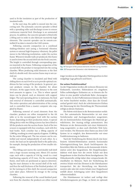
Fig. 10 Transport of the precast elements into the curing chamber.<br />
Abb. 10 Transport der Elemente in die Härtekammer.<br />
träger werden an der folgenden Palettenposition in ihre<br />
endgültige Lage gebracht und fi xiert.<br />
Der weitere Produktionsablauf<br />
An der Folgestation werden alle weiteren Elemente wie<br />
Einbauteile, Leerrohre, Elektrodosen etc. eingebaut.<br />
Fallen aufwändigere Einbauten an, so können die Paletten<br />
in eine parallel verlaufende Bahn „herausgezogen“<br />
werden. In drei Pufferstationen können die Paletten<br />
weiter bearbeitet werden, ohne dass der Grundumlauf<br />
gestört wird. Auch der arbeitsintensive Einbau<br />
der Dämmung bei der Herstellung der Thermowände<br />
erfolgt an diesen Stationen.<br />
Die Palette wird dann in die Betonierstation verfahren.<br />
Der automatische Betonverteiler ist mit einer<br />
Verteilerwalze und Austragsschnecken ausgerüstet,<br />
die ein kontinuierliches Einbringen des Materials gewährleisten.<br />
Der Austrag erfolgt automatisiert. Des<br />
Weiteren ist der Betonverteiler mit einer Hubeinrichtung<br />
ausgestattet, so dass auch überhohe Teile betoniert<br />
werden. Für Elemente ohne Daten aus dem CAD<br />
System ist es möglich, den Betonverteiler mit einer<br />
Funkfernsteuerung zu bedienen.<br />
Nach der Verdichtung des Betons durch eine kombinierte<br />
Schüttel-Rüttelstation (mittels horizontaler<br />
Schwingeinrichtung bzw. durch hochfrequente Außenrüttler)<br />
fährt die Palette an die kommende Arbeitsstation<br />
unter den Saugrahmen. Bei Doppelwandproduktion<br />
wird dann hier die zweite Schale mit dem<br />
Saugrahmen in den frischen Beton herabgelassen. Die<br />
Höhenkontrolle erfolgt dabei über entsprechende Abstandhalter<br />
im Rahmen. Nach der Verdichtung der<br />
zweiten Schale wird das Element in die Härtekammer<br />
transportiert. Bei der Herstellung von Massivelementen<br />
oder aber der ersten Schale einer Doppelwand<br />
entfällt dieser Arbeitsgang unter dem Saugrahmen<br />
selbstverständlich.<br />
Die Härtekammer ist isoliert und verfügt über<br />
Schiebetorsegmente pro Etage, so bietet sie optimale<br />
Produktion<br />
1<br />
9