Allround Scaffolding - Layher
Allround Scaffolding - Layher
Allround Scaffolding - Layher

Create successful ePaper yourself
Turn your PDF publications into a flip-book with our unique Google optimized e-Paper software.
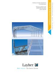
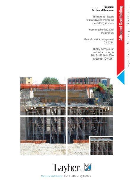
Propping<br />
Technical Brochure<br />
The universal system<br />
for everyday and engineered<br />
scaffolding solutions<br />
made of galvanised steel<br />
or aluminium<br />
General construction approval<br />
Z-8.22-64<br />
Quality management<br />
certified according to<br />
DIN EN ISO 9001:2000<br />
by German TÜV-CERT<br />
<strong>Allround</strong> <strong>Scaffolding</strong><br />
I n g e n i o u s . S t r o n g . L i m i t l e s s .
Faster. Stronger. Safer. More Profitable.
Introduction<br />
<strong>Layher</strong>’s <strong>Allround</strong> <strong>Scaffolding</strong>® makes an ideal propping system:<br />
• being both a scaffolding and a propping system it is economic and versatile<br />
• it has extremely high strength capacity values, is self supporting and is quick to install<br />
<strong>Allround</strong> in standard configurations up to six metres in height is rated for the following permissible loadings:<br />
• with lifts of 2.0 metres – up to 45 kN per standard<br />
• with lifts of 1.5 metres – up to 60 kN per standard<br />
• with lifts of 1.0 metres – up to 70 kN per standard<br />
(see Tables 3a & 3b on pages 8-9 for details)<br />
Permissible loadings can be increased considerably further by:<br />
• using <strong>Layher</strong>’s reinforced base jacks and head jacks (U-heads)<br />
• additional bracing (ledgers and diagonals), and/or<br />
• joining standards with our unique twin wedge couplers<br />
For example, a single 1.09 m x 1.09 m heavy duty <strong>Allround</strong> tower can support loads of close to 700 kN (see example on pages 11-12)<br />
or even higher.<br />
Appropriate static calculations should be performed to prove the appropriate configuration of <strong>Allround</strong> components for each<br />
individual situation.<br />
1
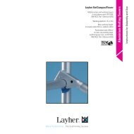
Required components for propping<br />
pressed-in spigot<br />
without spigot<br />
Standard, steel<br />
400 500<br />
100 200<br />
Dimensions<br />
Maße<br />
Base collar Base collar, long Base plate 60 Base plate 80,<br />
reinforced<br />
Swivelling base plate 60,<br />
reinforced<br />
Base plate 60,<br />
solid, without lock<br />
2<br />
Hinged pin<br />
dia. 12 mm<br />
Spigot Special bolt<br />
M 12 x 60,<br />
with nut<br />
Wedge head coupler, double
Required components for propping<br />
Description Length (m) Approximate Weight (kg) Ref. No.<br />
Standard, steel,<br />
with pressed-in spigot<br />
Standard, steel, without spigot<br />
e.g. for receiving head jacks, or for<br />
suspended scaffolding use the spigot<br />
Ref. No. 2605.000<br />
Spigot<br />
for Ref. No. 2604<br />
0.5<br />
1.0<br />
1.5<br />
2.0<br />
2.5<br />
3.0<br />
4.0<br />
0.5<br />
1.0<br />
1.5<br />
2.0<br />
2.5<br />
3.0<br />
4.0<br />
2.9<br />
5.5<br />
7.8<br />
10.2<br />
12.2<br />
14.6<br />
19.1<br />
2.5<br />
4.5<br />
6.8<br />
9.0<br />
11.7<br />
13.7<br />
18.4<br />
5603.050<br />
2603.100<br />
2603.150<br />
2603.200<br />
2603.250<br />
2603.300<br />
2603.400<br />
2604.050<br />
2604.100<br />
2604.150<br />
2604.200<br />
2604.250<br />
2604.300<br />
2604.400<br />
0.52 1.6 2605.000<br />
Hinged pin, dia. 12 mm 0.1 4905.555<br />
Special bolt M 12 x 60, with nut 0.08 4905.060<br />
Base collar 0.24 1.6 2602.000<br />
Base collar, long 0.43 2.7 2660.000<br />
Base plate 60<br />
(max. spindle travel 41 cm)<br />
Base plate 80, reinforced<br />
(max. spindle travel 55 cm)<br />
Swivelling base plate 60, reinforced<br />
(max. spindle travel 32 cm), ensure<br />
sufficient structural strength<br />
Base plate 60, solid, without lock<br />
(max. spindle travel 41 cm)<br />
Wedge head coupler, double<br />
for connecting several standards<br />
to each other<br />
0.6 3.6 4001.060<br />
0.8 4.9 4002.080<br />
0.6 6.1 4003.000<br />
0.6 6.7 5602.060<br />
3<br />
1.6 2628.000
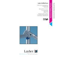
Required components for propping<br />
39<br />
39 39<br />
Head jack 60,<br />
solid, 14 cm<br />
Base piece for<br />
heavy-duty support<br />
39<br />
26<br />
39 39<br />
39<br />
26 26 39 39<br />
Head jack 60 and 45,<br />
solid, 16 cm<br />
39<br />
26<br />
39<br />
39<br />
26<br />
� Horizontal 26 support elements, side protection<br />
39<br />
26<br />
Depending on the scaffolding bay length, deck<br />
type and load, � Ledgers made of steel or aluminium<br />
are available in cylindrical tube, channel section<br />
and reinforcement Swivelling sections head for higher loads.<br />
The ledgers jack are deck 60 beams, and 45, bracing solidelements<br />
and<br />
guard rails.<br />
The wedge lock connection ensures self-aligning<br />
and rigid connection with central load introduction<br />
between vertical standards and ledgers.<br />
Safety is already assured in the assembled state<br />
since the wedge lock already prevents unintentional<br />
disengagement when the wedge is loosely<br />
inserted.<br />
Longitudinal ledgers can be omitted at deck level if<br />
the decks are secured Base against plate for lifting off by a lift-off<br />
preventer. heavy-duty support<br />
Ledger-deck configuration<br />
0.45 m 1 x 0.32 m<br />
0.73 m 2 x 0.32 m or 1 x 0.61 m<br />
1.09 m 3 x 0.32 m or 1 x 0.61 m + 1 x 0.32 m<br />
1.40 m 4 x 0.32 m or 2 x 0.61 m<br />
1.57 m 4 x 0.32 m and 1 x 0.19 m<br />
2.07 m 6 x 0.32 m<br />
2.57 m 7 x 0.32 m and 1 x 0.19 m<br />
3.07 m 9 x 0.32 m<br />
Bearing capacity steel ledgers *<br />
Ledger length<br />
(system 0.73 1.09 1.40 1.57 2.07 2.57 3.07<br />
Cross head jack 60 and 45,<br />
solid<br />
The wedge head is simply<br />
pushed over the rosette.<br />
4<br />
The wedge is inserted in<br />
one of the openings.<br />
Dimensions<br />
O-ledger<br />
Diagonal brace, steel<br />
Head jack 60,<br />
reinforced, 18 cm<br />
Head jack for<br />
heavy-duty support<br />
Head piece for<br />
heavy-duty support<br />
A hammer blow on the<br />
wedge transforms the<br />
positive connection into<br />
a non-positive one.<br />
� Ledger<br />
� Metric ledger<br />
� Ledger, reinforced<br />
� U transverse ledger
Required components for propping<br />
Description Length (m) Approximate Weight (kg) Ref. No.<br />
Head jack 60, solid, 14 cm (max. spindle<br />
travel 39 cm), effective width of fork 14 cm<br />
Head jack, solid, 16 cm (max. spindle travel<br />
39 cm and 26 cm), effective width of fork 16 cm<br />
Head jack 60, reinforced, 18 cm (max. spindle<br />
travel 39 cm), effective width of fork 18 cm<br />
Swivelling head jack, solid, 16 cm (max. spindle<br />
travel 39 cm and 26 cm), effective width of fork 16 cm<br />
Cross head jack, solid (max. spindle travel 39 cm<br />
and 26 cm), opening dimensions 8.5 / 17 cm<br />
0.58 7.4 5313.060<br />
0.58<br />
0.45<br />
7.5<br />
6.6<br />
5314.060<br />
5314.045<br />
0.58 7.5 5316.060<br />
0.58<br />
0.45<br />
0.58<br />
0.45<br />
8.2<br />
7.3<br />
7.9<br />
6.9<br />
5312.000<br />
5312.045<br />
5315.060<br />
5315.045<br />
Head jack for heavy-duty support 0.7 30.9 5312.004<br />
Head piece for heavy-duty support 0.21 7.1 5312.003<br />
Base plate for heavy-duty support 0.7 24.1 5312.001<br />
Base piece for heavy-duty support 0.4 11.5 5312.002<br />
O-ledger, steel<br />
The 0.39 m ledger is used on the 0.39 m bracket<br />
for fall protection at the end. The 1.04 m ledger<br />
corresponds to half the 2.07 m bay. The 1.29 m<br />
ledger corresponds to half the 2.57 m bay.<br />
The ledger 0.90 m is used for construction of the<br />
equalising modular stairway.<br />
Diagonal brace, steel<br />
for 0.73 m bay length, 2.0 m bay height<br />
for 1.04 m bay length, 2.0 m bay height<br />
for 1.09 m bay length, 2.0 m bay height<br />
for 1.40 m bay length, 2.0 m bay height<br />
for 1.57 m bay length, 2.0 m bay height<br />
for 2.07 m bay length, 2.0 m bay height<br />
for 2.57 m bay length, 2.0 m bay height<br />
for 3.07 m bay length, 2.0 m bay height<br />
for 4.14 m bay length, 2.0 m bay height<br />
for 0.73 m bay length, 1.0 m bay height<br />
for 0.73 m bay length, 1.5 m bay height<br />
for 1.09 m bay length, 0.5 m bay height<br />
for 1.09 m bay length, 1.0 m bay height<br />
for 1.09 m bay length, 1.5 m bay height<br />
for 1.57 m bay length, 0.5 m bay height<br />
for 1.57 m bay length, 1.0 m bay height<br />
for 1.57 m bay length, 1.5 m bay height<br />
for 2.07 m bay length, 0.5 m bay height<br />
for 2.07 m bay length, 1.0 m bay height<br />
for 2.07 m bay length, 1.5 m bay height<br />
for 2.57 m bay length, 0.5 m bay height<br />
for 2.57 m bay length, 1.0 m bay height<br />
for 2.57 m bay length, 1.5 m bay height<br />
for 3.07 m bay length, 0.5 m bay height<br />
for 3.07 m bay length, 1.0 m bay height<br />
for 3.07 m bay length, 1.5 m bay height<br />
0.25<br />
0.39<br />
0.45<br />
0.73<br />
0.90<br />
1.04<br />
1.09<br />
1.29<br />
1.40<br />
1.57<br />
2.07<br />
2.57<br />
3.07<br />
4.14<br />
2.12<br />
2.23<br />
2.25<br />
2.40<br />
2.49<br />
2.81<br />
3.18<br />
3.58<br />
4.51<br />
1.20<br />
1.65<br />
1.10<br />
1.41<br />
1.81<br />
1.55<br />
1.79<br />
2.11<br />
2.03<br />
2.20<br />
2.48<br />
2.51<br />
2.66<br />
2.89<br />
3.00<br />
3.13<br />
3.32<br />
5<br />
1.6<br />
2.1<br />
2.4<br />
3.4<br />
3.9<br />
4.4<br />
4.6<br />
5.3<br />
5.8<br />
6.3<br />
8.2<br />
10.0<br />
12.0<br />
15.1<br />
7.3<br />
7.6<br />
7.7<br />
8.1<br />
8.4<br />
9.2<br />
10.3<br />
11.4<br />
14.0<br />
4.2<br />
5.4<br />
4.0<br />
4.8<br />
5.8<br />
5.7<br />
6.3<br />
7.3<br />
7.2<br />
7.4<br />
8.2<br />
8.4<br />
8.8<br />
9.5<br />
9.6<br />
9.9<br />
10.5<br />
2607.025<br />
2607.039<br />
2607.045<br />
2607.073<br />
2607.090<br />
2607.103<br />
2607.109<br />
2607.129<br />
2607.140<br />
2607.157<br />
2607.207<br />
2607.257<br />
2607.307<br />
2607.414<br />
2620.073<br />
2620.104<br />
2620.109<br />
2620.140<br />
2620.157<br />
2620.207<br />
2620.257<br />
2620.307<br />
2620.414<br />
2621.001<br />
2621.002<br />
2621.008<br />
2621.006<br />
2621.007<br />
5606.050<br />
5606.100<br />
5606.150<br />
5609.050<br />
5609.100<br />
5609.150<br />
5607.050<br />
5607.100<br />
5607.150<br />
5610.050<br />
5610.100<br />
5610.150
Loading on base plates<br />
Tables 1a-d and 2a-c show the allowable loading for the <strong>Layher</strong> base plates and U-head jacks for different horizontal loadings (%)<br />
and extended heights. Intermediate values can be linearly interpolated. The loadings apply to centrically loaded base jacks and U-head<br />
jacks with a vertical load eccentricity of up to 5 mm off centre at the head jacks (exception: if the swivelling head jack 60 solid is used<br />
the load can be applied centrically). In the case of single beams, the bracket head must be rotated or packing should be inserted at left<br />
and right (see Figure 9, page 16). In the case of support structures for heights up to 6.50 m, a horizontal load of 2% applies. For higher<br />
support structures this is 3%.<br />
TABLE 1a<br />
* 370 mm = maximum possible spindle extension<br />
b<br />
c<br />
d<br />
Load-bearing capacity of base plate 60 [kN] (Ref. No.: 4001.060)<br />
Horizontal load Extended distance [mm]<br />
100 200 300 370*<br />
0% 62.6 60.4 57.7 55.4<br />
1% 60.2 56.2 52.0 48.9<br />
2% 55.8 49.6 43.7 39.9<br />
3% 52.0 44.3 37.7 33.8<br />
4% 48.6 39.9 33.1 29.2<br />
5% 45.7 36.1 29.4 25.7<br />
Horizontal<br />
load<br />
Load-bearing capacity of base plate 80 reinforced [kN] (Ref. No.: 4002.080)<br />
Extended distance [mm]<br />
100 200 300 400 500<br />
0% 76.4 73.4 69.7 64.4 57.2<br />
1% 73.3 68.0 62.1 55.6 48.5<br />
2% 67.6 59.2 51.5 44.4 37.9<br />
3% 62.6 52.3 43.8 37.0 31.3<br />
4% 58.3 46.8 38.2 31.7 26.6<br />
5% 54.5 42.1 33.7 27.7 23.1<br />
Load-bearing capacity of base plate 60 solid [kN] (Ref. No.: 5602.060)<br />
Horizontal load Extended distance [mm]<br />
100 200 300 400<br />
0% 179.1 166.2 146.3 118.8<br />
1% 168.1 147.5 123.6 98.9<br />
2% 149.5 120.7 95.5 75.7<br />
3% 134.2 101.8 78.2 61.5<br />
4% 121.5 88.0 66.2 51.6<br />
5% 110.6 77.0 57.2 44.6<br />
Horizontal<br />
load<br />
Load-bearing capacity of swivelling base plate [kN] (Ref. No.: 4003.000)<br />
Extended distance [mm]<br />
50 100 200 300 340<br />
0% 44.5 44.5 44.5 44.5 44.5<br />
1% 44.3 44.3 44.3 44.3 34.2<br />
2% 44.1 44.1 44.1 44.1 40.4<br />
3% 43.9 43.9 43.9 37.1 33.4<br />
4% 43.7 43.7 42.2 31.8 28.5<br />
5% 43.5 43.5 37.7 27.7 24.7<br />
6<br />
55<br />
150<br />
182<br />
150<br />
150<br />
5 560<br />
5 730<br />
8 600<br />
572<br />
8
Loading on head jacks<br />
TABLE 2a<br />
b<br />
Load-bearing capacity of head jack, solid [kN]*<br />
(Ref. No.: 5313.060 head jack – effective width of fork = 14 cm<br />
Ref. No.: 5314.045 and 5314.060 head jack – effective width of fork = 16 cm<br />
Ref. No.: 5315.045 and 5315.060 crosshead jack – opening dimensions 18.5/17 cm)<br />
Horizontal load Extended distance [mm]<br />
100 200 260 300 390<br />
0% 107.9 93.3 83.0 75.6 59.7<br />
1% 103.0 86.3 75.8 68.9 53.9<br />
2% 94.3 74.6 64.3 57.9 45.0<br />
3% 86.3 65.7 55.6 49.9 38.4<br />
4% 80.0 58.4 49.0 43.7 33.6<br />
5% 74.3 52.5 43.6 38.8 29.8<br />
* According to EN 12812, 2004, par. 9.3.6 the loads have been assessed to be acting at 5 cm load eccentricity because there is<br />
no centring device.<br />
Do not exceed the maximum allowed extended distance of 260 mm (5314.045 / 5315.045) res. 390 mm (5314.060 / 5315.060 /<br />
5316.060)!<br />
c<br />
Load-bearing capacity of head jack 60, reinforced [kN]*<br />
(Ref. No.: 5316.060 – effective width of fork = 18 cm)<br />
Horizontal load Extended distance [mm]<br />
100 200 300 390<br />
0% 53.01 48.23 42.13 35.11<br />
1% 51.05 45.19 38.58 31.83<br />
2% 47.57 40.18 33.04 26.76<br />
3% 44.51 36.04 28.81 23.00<br />
4% 41.78 32.57 25.46 20.15<br />
5% 39.38 29.68 22.78 17.80<br />
Load-bearing capacity of swivelling head jack, solid [kN]**<br />
(Ref. No.: 5312.045 and 5312.000 – effective width of fork = 16 cm)<br />
Horizontal load Extended distance [mm]<br />
100 200 260 300 390<br />
0% 178.1 160.9 144.0 129.4 91.4<br />
1% 166.2 140.1 121.0 107.6 77.1<br />
2% 146.3 112.1 93.1 82.0 59.5<br />
3% 130.5 93.3 75.9 66.5 48.5<br />
4% 117.4 79.6 64.1 55.8 40.9<br />
5% 106.2 69.4 55.2 48.1 35.2<br />
** The loads have been assessed to be acting centrically thanks to the articulated mounting of the top plate which acts as<br />
centring device.<br />
Do not exceed the maximum allowed extended distance of 260 mm (5312.045) res. 390 mm (5312.000)!<br />
Packing under base jacks<br />
If the support structure cannot be assembled in, for instance, an area with an existing floor or<br />
foundation beams, it is necessary to place sole boards underneath the base plates. This must be done<br />
in such a way that there is no possibility, when the formwork is rinsed clean, during the pouring and<br />
the curing of the concrete or during heavy rain, of undesired settling or subsidence occurring.<br />
On compacted ground, packing with a minimum plan area of 0.25 m2 (Figure 1 below) is generally<br />
sufficient. If in doubt, soleboards or similar material need to be laid on the ground.<br />
7<br />
Head jack, solid<br />
400<br />
450 / 580<br />
Crosshead jack, solid<br />
580<br />
Head jack 60, reinforced<br />
Swivelling head jack, solid<br />
Figure 1<br />
Placing sole boards<br />
under base plates<br />
+<br />
– 600<br />
450 / 580<br />
450 / 580
Diagonal bracing configurations and allowable standard loadings<br />
For the <strong>Allround</strong> system to be able to accommodate the horizontal stabilisation forces, it is essential that diagonal bracing be installed<br />
at all times. Free-standing individual support towers (rule from experience: the maximum height of which may not exceed 4x smallest<br />
base dimension!) and start and end bays must have diagonal bracing installed.<br />
Note that, diagonal bracing must be installed, in both directions, in (O) every, (A) every 2nd, (B) every 3rd, (C) every 4th, or (D) every<br />
5th bay. The diagonal bracing configurations are shown in Figure 2, page 10. The combined bay size/diagonal bracing configuration<br />
determines the allowable loading for the <strong>Allround</strong> standards. A diagonal bracing configuration needs to be chosen in accordance with<br />
Tables 3a-b for each bay size in Tables 5a-c to 6a-c or for independently calculated bay sizes.<br />
TABLE 3a<br />
Permissible loading to <strong>Allround</strong> standards depending on diagonal bracing patterns<br />
Bay Size<br />
[mm]<br />
732<br />
1088<br />
1400<br />
1572<br />
2072<br />
2572<br />
3072<br />
Diagonal bracing pattern<br />
(see page 10)<br />
Permissible loadings on standards [kN]<br />
(for total standard height to<br />
6.00 m and lift height 2 m)<br />
Middle standard Exterior standard<br />
A 33.6 33.6<br />
B 30.8 30.8<br />
C 29.4 29.4<br />
D 26.8 26.8<br />
A 43.4 35.6<br />
B 38.9 34.4<br />
C 37.7 32.4<br />
D 35.8 30.8<br />
A 44.4 36.4<br />
B 42.4 35.2<br />
C 40.4 34.0<br />
D 38.5 32.7<br />
A 45.2 36.6<br />
B 43.0 36.1<br />
C 41.3 35.1<br />
D 40.1 34.0<br />
A 45.0 36.9<br />
B 43.8 36.6<br />
C 42.4 36.0<br />
D 41.5 35.3<br />
A 44.2 37.2<br />
B 43.5 36.7<br />
C 42.2 36.3<br />
D 41.5 35.7<br />
A 43.9 36.6<br />
B 43.0 36.6<br />
C 42.4 36.1<br />
D 41.9 35.7<br />
8
Diagonal bracing configurations and allowable standard loadings<br />
If it is not possible to fix system ledgers and diagonal braces onto the top rosette of the standards or if the <strong>Allround</strong> base collar is left<br />
out, the allowable standard loading will be reduced.<br />
If in such situations the allowable loading for the standards is exceeded, add additional diagonal bracing or reduce the bay size.<br />
In these cases, individual static calculation is required.<br />
TABLE 3b<br />
Lift heights 1.5 m and 1.0 m<br />
Bay size<br />
[mm]<br />
1572<br />
2072<br />
2572<br />
3072<br />
Diagonal<br />
bracing pattern<br />
see page 10<br />
Permissible loadings on standards [kN]<br />
for total standard height to 6.00 m<br />
Lift height 1.5 m Lift height 1.0 m<br />
Middle standard Exterior standard Middle standard Exterior standard<br />
O 60.9 53.0 73.0 62.8<br />
A 58.4 51.4 68.8 61.9<br />
B 57.1 49.6 66.8 60.1<br />
C 55.4 48.2 63.9 57.5<br />
D 53.6 46.6 61.3 55.2<br />
O 60.5 52.6 72.5 62.4<br />
A 58.7 51.6 69.7 62.0<br />
B 57.8 50.9 68.2 61.4<br />
C 56.5 49.7 66.6 59.9<br />
D 55.3 48.7 64.9 58.4<br />
O 59.8 52.0 72.1 62.7<br />
A 58.3 51.7 70.2 61.8<br />
B 57.3 50.5 68.8 61.2<br />
C 56.9 50.1 67.4 60.7<br />
D 55.9 49.2 66.6 59.4<br />
O 58.9 51.9 71.7 62.4<br />
A 57.8 51.4 69.9 62.2<br />
B 57.3 51.0 68.8 61.9<br />
C 56.6 49.8 67.6 60.9<br />
D 55.8 49.1 66.3 58.3<br />
Permissible loadings on on standards can be increased further by adding additional standards, ledgers and/or diagonals.<br />
Static calculations are required for this.<br />
9
Diagonal bracing configurations and allowable standard loadings<br />
Figure 2<br />
Diagonal<br />
bracing<br />
configurations<br />
O: diagonal bracing every bay A: diagonal bracing every 2nd bay B: diagonal bracing every 3rd bay C: diagonal bracing every 4th bay D: diagonal bracing every 5th bay<br />
The selected diagonal bracing configuration plus diagonal bracing in the start and end bays can result in a denser pattern (or even two<br />
adjoining sections with diagonal bracing) at the end of the support structure.<br />
In Figure 3a and 3b combinations of different diagonal bracing configurations are shown in one direction only. The same bracing pattern<br />
should also be used in the perpendicular direction as shown in Figure 2.<br />
Figure 3a<br />
Diagonal bracing configuration C & A<br />
Figure 3b<br />
Diagonal bracing configuration C & B<br />
E = exterior standard<br />
M = middle standard<br />
C C A<br />
B C B<br />
10
Heavy duty towers and columns<br />
In applications where the load-bearing capacities of traditional falsework towers are exceeded, it is possible to use the heavy duty<br />
towers and columns using <strong>Allround</strong> <strong>Scaffolding</strong>.<br />
Heavy duty spindles fit into specially designed heavy-duty top and bottom collars. This grouping of the standards allows a large increase<br />
in the capacity over individual standards. An extremely high load-bearing capacity is achieved by combining four <strong>Allround</strong> standards.<br />
This support can be used in a number of arrangements with various load-bearing capacities: a heavy duty tower or a heavy duty column.<br />
These arrangements can be further expanded by using <strong>Layher</strong> <strong>Allround</strong> standard components to cater for a vast variety of irregularly<br />
shaped areas.<br />
Figure 4a Heavy Duty Tower Figure 4a Heavy Duty Column<br />
11
Heavy duty towers and columns<br />
TABLE 4a<br />
Load bearing capacity – heavy duty column – permissible loads for one <strong>Allround</strong> heavy duty column [kN]<br />
Inclination of the column vertical 45 o Horizontal<br />
Distance between the wedge head<br />
couplers [m]<br />
0.5 1.0 0.5 1.0 0.5 1.0<br />
Column height H 2 m 223.4 215.8 219.2 211.8 218.0 210.2<br />
3 m 212.0 191.0 205.2 182.4 203.0 179.4<br />
4 m 195.6 146.6 182.8 133.4 178.0 129.0<br />
5 m 170.0 121.2 150.2 102.2 142.0 95.4<br />
6 m 147.2 104.0 123.4 81.8 112.4 72.0<br />
7 m 133.6 88.2 100.6 62.4 89.0 –<br />
8 m 112.8 74.0 – – – –<br />
maximum extension of the base jack ≤ 250 mm; maximum extension of the top jack ≤ 250 mm<br />
0.77 m ≤ (a 1 + a 2 ) ≤ 1.27 m<br />
TABLE 4b<br />
Load bearing capacity – heavy duty tower – permissible loads [kN] for one <strong>Allround</strong> heavy duty tower 1.09 x 1.09 m<br />
Tower<br />
height H<br />
4 m<br />
6 m<br />
8 m<br />
10 m<br />
12 m<br />
16 m<br />
20 m<br />
Anchoring on top<br />
Free standing<br />
0* 1.6* 3.2* 4.8* 6.4* 8.0* 9.6*<br />
w/o wind 632.8 655.2 641.6 576.0 494.4 404.4 301.6 171.2<br />
with wind** 632.8 655.2 641.6 573.6 490.4 399.2 292.0 145.6<br />
w/o wind 667.2 694.4 646.4 572.8 492.0 402.4 301.6 178.4<br />
with wind** 667.2 674.4 596.0 512.0 424.0 321.6 192.8 –<br />
w/o wind 672.8 680.8 642.4 564.8 482.4 392.8 292.8 173.6<br />
with wind** 672.8 610.4 523.4 439.2 340.8 215.2 – –<br />
w/o wind 687.2 665.6 629.6 552.2 496.6 381.6 280.8 –<br />
with wind** 641.6 – – – – – – –<br />
w/o wind 687.2 651.2 615.2 537.6 456.0 367.2 267.2 –<br />
with wind** 572.8 – – – – – – –<br />
w/o wind 677.6 620.0 580.8 504.8 421.6 331.2 – –<br />
with wind** 440.0 – – – – – – –<br />
w/o wind 669.6 584.8 535.2 461.6 367.8 – – –<br />
with wind** 304.0 – – – – – – –<br />
* acting horizontal load on top of standard [kN] Spindle extension ≤ 250 mm<br />
** assumed wind loads result from: q = 0.5 kN/m2 (v = 28.3 m/s) for H ≤ 8 m<br />
q = 0.8 kN/m2 (v = 35.8 m/s) for H ≤ 8 m<br />
q is the velocity pressure, v is the equivalent wind speed, and H is the height above the ground.<br />
12
Loading on <strong>Allround</strong> standards<br />
The vertical load on the <strong>Allround</strong> support structure is determined by the density of the concrete, the thickness of the floor, the weight<br />
of the formwork and the pouring load.<br />
The density of the concrete, the weight of the formwork and the pouring load can vary from situation to situation. The free fall of the<br />
concrete must not be from a height greater than 1.0 m and an excessive amount of weight in any one spot must be avoided.<br />
The vertical loading (kN/m 2 ) for evenly distributed loads on the <strong>Allround</strong> support structure can be calculated as follows:<br />
(Concrete density x floor thickness + formwork weight + pouring load)<br />
x safety factor 1.15 (EN 12812 design class B2).<br />
The loading on the standards can be calculated by multiplying the <strong>Allround</strong> section surface area and the load per m2 .<br />
(Loading on standards = (x) x (y) x vertical loading per m2 ).<br />
Figure 5<br />
Loading on<br />
standards for evenly<br />
distributed load<br />
Where only the strength of the <strong>Allround</strong> standards need to be considered, the bay sizes and diagonal bracing configuration can be<br />
selected according to Table 3a-b, pages 8-9. However, the allowable loadings on jacks must not be exceeded.<br />
In many situations what will determine the critical bay size is not the strength of the <strong>Allround</strong> components but the formwork or the<br />
broad slab floor. This is discussed on pages 16-19, Tables 5a-c and 6a-c. In these tables the following (mean) values are used for the<br />
calculations:<br />
Density of reinforced concrete 25.0 kN/m3 Weight of the formwork for the floor (cross beams, longitudinal beams, plywood sheeting) 1.0 kN/m2 Pouring load (free fall less than 1.0 m) 1.5 kN/m2 Maximum height of the support structure for in situ pouring 6.5 m<br />
These values should first be checked before using Tables 5a-c and 6a-c.<br />
x<br />
y<br />
y<br />
The support structures for floors that are to be poured in situ are worked out in more detail on pages 16-19, Tables 5a-c and 6a-c. Where<br />
loads are not evenly distributed, e.g. in the case of floor joists or walls that need to be poured in situ, the support structure must be<br />
calculated separately.<br />
13<br />
x
Loading on <strong>Allround</strong> standards and lift height<br />
The lift height is defined as the height between floors minus the thickness of the floor that is being poured. The total length of the<br />
standards of an <strong>Allround</strong> support structure is the lift height minus the height of the formwork, minus the minimum sizes of the <strong>Allround</strong><br />
base collar and the base and U-head jacks. The minimum sizes of these last components are as follows:<br />
base jack 45 mm (not extended)<br />
U-head jack 50 mm (not extended)<br />
base collar 165 mm<br />
260 mm<br />
If the <strong>Allround</strong> base collar is not used, a measurement of 95 mm can be used in the calculation instead of 260 mm (however, individual<br />
static calculations for the <strong>Allround</strong> standards are required).<br />
Some examples have been provided of the sum of the minimum <strong>Allround</strong> sizes and the customary formwork measurements in Figures<br />
6 and 7. The difference between the lift height and these totals must be rounded down to the nearest 500 mm. The result is the total<br />
required length of the standard.<br />
The remaining height should generally be distributed over the base and U-head jacks. To allow for the room required to disassemble the<br />
formwork, the head jacks must always be extended by 80 mm.<br />
Figure 6 Required length of standard – Example 1<br />
Formplate 21 mm<br />
Top beam 160 mm<br />
Lower beam 160 mm<br />
U-head jack 50 mm<br />
(not extended)<br />
Figure 6a Figure 6b<br />
Base collar 165 mm<br />
Base jack 45 mm+<br />
(not extended)<br />
Total 601 mm<br />
14<br />
Formplate 21 mm<br />
H20 beam 200 mm<br />
H20 beam 200 mm<br />
U-head jack 50 mm<br />
(not extended)<br />
Base collar 165 mm<br />
Base jack 45 mm+<br />
(not extended)<br />
Total 681 mm
Loading on <strong>Allround</strong> standards and lift height<br />
Figure 7 Required length of standard – Example 2<br />
Timber beam 160 mm<br />
U-Head jack 50 mm<br />
(not extended)<br />
Figure 7a Figure 7b<br />
Base collar 165 mm<br />
Base jack 45 mm+<br />
(not extended)<br />
Total 420 mm<br />
H 20 beam 200 mm<br />
U-head jack 50 mm<br />
(not extended)<br />
Base collar 165 mm<br />
Base jack 45 mm+<br />
(not extended)<br />
Total 460 mm<br />
Calculation example: mm mm<br />
Height between floors 6200 6000<br />
Floor thickness -230 -250<br />
Lift height 5970 5750<br />
Formwork and minimum dimensions of <strong>Allround</strong> base collar,<br />
base and U-head jacks (Figure 6a) -601 -601<br />
Subtotal 5369 5149<br />
Subtotal rounded down to nearest 500 mm (= standard length) 5000 5000<br />
Head jack extension 189 80<br />
Base jack extension 180 69<br />
15
<strong>Allround</strong> support structures for formwork<br />
Formwork consisting of cross beams, longitudinal beams and plywood sheeting can be supported efficiently by standard <strong>Allround</strong><br />
system components.<br />
In many cases it is not the strength of the <strong>Allround</strong> components that determines the critical size of the sections, but the formwork itself.<br />
The strength of the formwork determines the amount of deflection. Base of tables 5a-c and 6a-c are these deflection limitations (which<br />
are widely used in Europe):<br />
- permissible deflection for ‘fair-faced’ work e.g. exposed concrete work such as exposed concrete soffits: 1/500 of the span<br />
- permissible deflection for ‘concealed’ work e.g. concrete soffits that are hidden by a ceiling: 1/333 of the span<br />
When the cross beams are doubled as shown, they must be laid from U-head jack to U-head jack: (see Figure 8 below).<br />
Figure 8 Using double cross beams<br />
For a support structure with single cross beams that are I-beams, it is important to ensure that the single cross beams are in the centre<br />
of U-head. This is achieved by rotating the bracket head or by inserting packing on either side of the cross beam (see Figure 9 below).<br />
N.B.: The loadings on the standards shown in Tables 1 to 6 must be checked against the load-bearing capacity of the base and U-head jacks. See Tables 7 and 8.<br />
Figure 9 Using single cross beams<br />
Figure The Figures 10a (Table in Tables 5a) 1 to 6 have been calculated for the support of a single floor (at a lift height of up to 6.5m). For multiple floors refer to Chapter Figure 8 ‘Multiple 10b (Table support 5b)<br />
<strong>Allround</strong> levels’. support structure with 60 x 160 mm timber<br />
<strong>Allround</strong> support structure with I-beams (e.g. Doka H20 beams)<br />
beams and plywood sheeting (double cross beams)<br />
and plywood sheeting (double cross beams)<br />
L3<br />
L1 L2<br />
Rotated head jack<br />
16<br />
Packed head jack<br />
Figure 10a below shows a support structure with standard <strong>Allround</strong> components and 60 x 160 mm timber beams. The cross beams have<br />
been doubled up.<br />
Figure 10b below shows a support structure with standard <strong>Allround</strong> components and I-beams (e.g. Doka H20 beams).<br />
L3<br />
L1<br />
L2
<strong>Allround</strong> support structures for formwork<br />
TABLE 5a <strong>Allround</strong> support structure with 60 x 160 mm timber beams and plywood sheeting (double cross beams)<br />
Floor<br />
thickness<br />
[mm]<br />
Longitudinal beam L3 spacing [mm]<br />
plywood 18 mm* plywood 21 mm*<br />
‘concealed<br />
work’<br />
‘fair-face<br />
work’<br />
‘concealed<br />
work’<br />
‘fair-face<br />
work’<br />
Bay sizes** [mm]<br />
L1 x L2<br />
Loading on<br />
standards<br />
[kN]<br />
≤ 100 850 720 900 800 2072 2072 24.7<br />
100-150 690 600 800 700 2072 2072 30.9<br />
150-220 650 550 740 630 1572 2072 30.0<br />
150-220 450 450 450 450 2572 1572 37.2<br />
220-260 400 400 400 400 2572 1400 37.3<br />
260-310 530 530 530 530 2072 1572 38.4<br />
310-360 480 480 480 480 2072 1400 38.4<br />
360-440 540 440 580 510 1572 1572 38.4<br />
440-500 480 420 550 480 1572 1400 38.0<br />
500-540 470 420 540 470 1400 1572 40.5<br />
540-630 450 380 520 440 1400 1400 41.1<br />
630-840 400 350 460 360 1400 1088 41.2<br />
840-1170 360 320 420 360 1088 1088 42.9<br />
1170-1400 340 300 390 340 732 1088 34.3 ***<br />
* These values may vary according to the timber used. Consult your timber supplier.<br />
** For each floor thickness the bay size for a larger floor thickness may be used.<br />
*** 34.3 kN represents a 2% higher load than stated in Table 3a for bay size 732 at bracing pattern A. This exceeding by 2% is acceptable.<br />
TABLE 5b <strong>Allround</strong> support structure with I-beams and plywood sheeting (double cross beams)<br />
Floor<br />
thickness [mm]<br />
Longitudinal beam L3 spacing [mm]<br />
plywood 18 mm* plywood 21 mm*<br />
‘concealed<br />
work’<br />
‘fair-face<br />
work’<br />
‘concealed<br />
work’<br />
‘fair-face<br />
work’<br />
Bay sizes** [mm]<br />
L1 x L2<br />
Loading on<br />
standards<br />
[kN]<br />
≤ 140 710 620 800 720 2572 2072 36.8<br />
140-210 650 560 750 650 2072 2072 38.3<br />
210-220 650 550 740 640 2572 1572 37.2<br />
220-260 580 520 670 590 2572 1400 37.3<br />
260-310 560 480 650 570 2072 1572 38.4<br />
310-360 530 460 610 530 2072 1400 38.4<br />
360-470 490 430 570 490 1572 1572 40.5<br />
470-540 470 420 540 490 1572 1400 40.5<br />
540-630 450 380 520 440 1400 1400 41.1<br />
630-840 400 350 460 400 1400 1088 41.2<br />
840-1170 360 320 420 360 1088 1088 43.2<br />
* These values may vary according to the beam used. Consult your beam supplier.<br />
** For each floor thickness the bay size for a larger floor thickness may be used.<br />
17
<strong>Allround</strong> support structures for formwork<br />
TABLE 5c <strong>Allround</strong> support structure with I-beams and plywood sheeting (single cross beams)<br />
Floor<br />
thickness<br />
[mm]<br />
Longitudinal beam L3 spacing [mm]<br />
plywood 18 mm* plywood 21 mm*<br />
‘concealed<br />
work’<br />
‘fair-face<br />
work’<br />
‘concealed<br />
work’<br />
‘fair-face<br />
work’<br />
Bay sizes**<br />
[mm]<br />
L1 x L2<br />
Loading on<br />
standards<br />
[kN]<br />
≤ 100 850 720 900 800 2572 2072 24.7<br />
100-150 690 600 800 700 2072 2072 30.9<br />
100-150 690 600 800 700 2572 1572 29.1<br />
150-180 680 580 770 670 2572 1400 29.0<br />
180-220 650 550 740 630 2072 1572 30.0<br />
220-250 640 540 730 620 2072 1400 29.2<br />
250-300 560 500 640 560 1572 1572 28.4<br />
300-340 540 470 630 540 1572 1400 27.8<br />
340-380 530 460 610 530 1400 1400 27.1<br />
380-500 480 420 550 480 1400 1088 26.3<br />
500-660 430 370 500 440 1088 1088 25.9<br />
660-1000 370 330 440 380 1088 732 25.2<br />
1000-1540 330 280 380 330 732 732 25.3<br />
* These values may vary according to the beam used. Consult your beam supplier.<br />
** For each floor thickness the bay size for a larger floor thickness may be used.<br />
NB. The loadings on the standards in tables 5a-c and 6a-c must be checked against the load-bearing capacity of the base and U-head jacks.<br />
<strong>Allround</strong> support structures for wide slab flooring<br />
L3<br />
L1<br />
Figure 10c (Table 5c)<br />
<strong>Allround</strong> support structure with H20 beams<br />
and plywood sheeting (single cross beams)<br />
For wide slab floors it is sufficient to have an in-line support structure of cross beams or I-beams. The <strong>Allround</strong> bay size (L1 x L2) is determined<br />
by the type of wide slab floor, the materials of the in-line support structure, and the thickness of the floor that will be poured.<br />
Figures 11a-c show <strong>Allround</strong> in-line support structures with double beams, single and double I-beams respectively.<br />
Tables 6a-c show the <strong>Allround</strong> bay size and resulting load on the standards for different floor thicknesses. The loading on the standards should<br />
be checked against the load-bearing capacity of the base and U-head jacks (Tables 1 and 2, pages 6-7).<br />
Double timber beams or I-beams must be laid from U-head jack to U-head jack (see Figure 8 page 16). Where single support beams are used<br />
they must bear centrically on the head jacks (see Figure 9, page 16).<br />
18<br />
L2
<strong>Allround</strong> support structures for wide slab flooring<br />
TABLE 6a <strong>Allround</strong> in-line support structure for wide slab floors with<br />
double 60 x 160 mm timber beams<br />
Floor thickness*<br />
[mm]<br />
TABLE 6b <strong>Allround</strong> in-line support structure with single I-beams<br />
Floor thickness*<br />
[mm]<br />
Bay sizes* [mm]<br />
L1 x L2<br />
Loading on<br />
standards [kN]<br />
≤ 180 1572 2072 22.5<br />
180-220 1400 2072 23.6<br />
220-260 1572 1572 22.0<br />
260-280 1088 2072 22.0<br />
280-400 1088 1572 26.6<br />
Floor thickness*<br />
[mm]<br />
Bay sizes** [mm]<br />
L1 x L2<br />
Bay sizes** [mm]<br />
L1 x L2<br />
* These values may vary according to the beam used. Consult your beam supplier.<br />
** For each floor thickness the bay size for a larger floor thickness may be used.<br />
Loading on<br />
standards [kN]<br />
≤ 220 1572 2072 26.2<br />
220-260 1400 2072 26.7<br />
260-360 1088 2072 27.2<br />
360-400 1088 1572 22.6<br />
* These values may vary according to the beam used. Consult your beam supplier.<br />
** For each floor thickness the bay size for a larger floor thickness may be used.<br />
* These values may vary according to the beam used. Consult your beam supplier.<br />
** For each floor thickness the bay size for a larger floor thickness may be used.<br />
TABLE 6c <strong>Allround</strong> in-line support structure with double I-beams<br />
Loading on<br />
standards [kN]<br />
≤ 250 1572 2072 36.1<br />
250-260 1400 2072 33.1<br />
260-380 1088 2572 35.4<br />
380-400 1088 2072 29.8<br />
19<br />
Figure 11a (Table 6a)<br />
<strong>Allround</strong> in-line support structure for wide slab<br />
floors with double 60 x 160 mm timber beams<br />
Figure 11b (Table 6b)<br />
<strong>Allround</strong> in-line support structure with<br />
single H20 beams<br />
L1<br />
L1<br />
L2<br />
Figure 11c (Table 6c)<br />
<strong>Allround</strong> in-line support with double H20 beams<br />
L1<br />
L2<br />
L2
Overhang for walkways and soffits<br />
The <strong>Layher</strong> <strong>Allround</strong> support structures can be extended quite simply with the use of base collars or 0.50 m standards and<br />
diagonal bracing.<br />
Depending on the floor thickness and the position of the soffit, one or two diagonals for each base collar or 0.5 m standard are normally<br />
sufficient for a walking platform (Figure 12a).<br />
A walking platform should be at least 60 cm wide and be fitted with toe boards and guard rails.<br />
If longer standards and several diagonal braces are used, the <strong>Allround</strong> overhang can carry much higher loads (Figure 12b). For such<br />
overhangs static calculations are required.<br />
Figure 12a<br />
Extending the <strong>Allround</strong> support<br />
structure with single diagonal bracing<br />
min. 60 cm<br />
0.50 m standard without spigot (2604.050) or base collar (2602.000)<br />
20<br />
Figure 12b<br />
Extending the <strong>Allround</strong> support<br />
structure with double diagonal bracing<br />
min. 60 cm
Multiple support levels<br />
After initial set a poured concrete floor takes time to reach its maximum strength.<br />
When there are multiple levels of support scaffolding, the support structure of floors that are not fully cured will also have to carry part<br />
of the load of the floor(s) and support structure above.<br />
Depending on how fast construction takes place, the total load on the lowest support structure could increase to more than the weight<br />
of two floors above.<br />
Where multiple levels are to be poured in a construction process a suitably qualified engineer should be consulted.<br />
Figure 13<br />
Multiple levels<br />
of <strong>Allround</strong><br />
support structures<br />
21
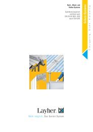
Supporting a free-standing façade with <strong>Allround</strong> <strong>Scaffolding</strong><br />
Figure 14<br />
Example of scaffold for free-standing façade<br />
<strong>Allround</strong> <strong>Scaffolding</strong> may support a free-standing façade, for example during renovation of historic buildings. The scaffold must be<br />
able to withstand the resulting wind loads and stabilisation loads. Individual static calculations are required.<br />
The scaffold must be tied into the façade as shown in the example in the diagram below (Figure 15).<br />
Figure 15<br />
Tying the scaffold into a free-standing façade<br />
22<br />
BALLAST
Supporting scaffolds for free-standing walls and façades<br />
In order to guarantee their stability, propping scaffolds must be equipped with ballast.<br />
Always use allround standards with bolt-in spigots!<br />
The amount and kind of the ballast depend mainly on the:<br />
• height of the wall<br />
• available space at the base in order to widen the scaffold<br />
• climatic conditions ( dynamic wind pressure)<br />
Figure 16<br />
Correct placement of Ballast<br />
WRONG CORRECT<br />
• do not load the ballast on the base collar level (no tension can be transferred) (see Figure 16 above).<br />
• don’t use fluid or grainy ballast.<br />
• carry out a static investigation.<br />
If the load capacity of the decks, standards or transoms has been reached (due to wind, dead load of scaffolding and ballast) then the<br />
standards may be embedded in a concrete foundation (see Figure 17 below).<br />
Figure 17<br />
Embedding vertical standards in concrete foundations<br />
23
Propping using <strong>Layher</strong> <strong>Allround</strong> <strong>Scaffolding</strong>®<br />
Faster<br />
Superior system technology<br />
Shorter assembly time<br />
Shorter dismantling time<br />
Lower labour costs<br />
Stronger<br />
Safer<br />
verified high load bearing capacity<br />
Eight connection points on each node<br />
Significantly less weight than other systems<br />
Lower transport costs<br />
General construction approval Z-8.22-64<br />
Certified consistent quality<br />
ISO 9001 TÜv certified<br />
Stable structure from base out<br />
More profitable<br />
Components can be used for propping or general scaffolding<br />
Increase available uses for your equipment<br />
Give clients a wider range of services<br />
Greater revenue<br />
Save time. Save money.<br />
24
Faster. Stronger. Safer. More Profitable.
We’re there for you. Wherever and whenever you need us.<br />
<strong>Layher</strong> in Germany<br />
Branches and delivery warehouses nationwide.<br />
<strong>Layher</strong> International<br />
Subsidiaries:<br />
Argentina, Australia, Austria, Belgium, Brazil, Bulgaria, Chile,<br />
Colombia, France, Greece, Hungary, India, Italy, Kazakhstan,<br />
Lithuania, Morocco, Netherlands, New Zealand, Norway,<br />
Peru, Poland, Russia, Serbia, Singapore, South Africa, Spain,<br />
Sweden, Switzerland, Turkey, United Kingdom, USA.<br />
Wilhelm <strong>Layher</strong> GmbH & Co. KG<br />
<strong>Scaffolding</strong> Grandstands Ladders<br />
Ochsenbacher Strasse 56<br />
D-74363 Gueglingen-Eibensbach<br />
Post Box 40<br />
D-74361 Gueglingen-Eibensbach<br />
Telephone +49 (0) 71 35 70-0<br />
Telefax +49 (0) 71 35 70-2 65<br />
E-Mail: export@layher.com<br />
www.layher.com<br />
Representatives:<br />
Croatia, Czech Republic, Denmark, Estonia, Finland, Hong<br />
Kong, Japan, Jordan, Kuwait, Latvija, Lebanon, Libya, Oman,<br />
Philippines, Romania, Saudi-Arabia, Slovakia, Slovenia,<br />
United Arab Emirates<br />
and many other countries.<br />
The <strong>Layher</strong> Product Range<br />
Protective<br />
Systems<br />
Event Systems<br />
<strong>Allround</strong> <strong>Scaffolding</strong><br />
Rolling Towers<br />
Ladders Accessories<br />
SpeedyScaf<br />
More Possibilities<br />
Ref. No. 8116.209 Edition 01.10.2010