reticulated structures on free-form surfaces - MERO-TSK ...
reticulated structures on free-form surfaces - MERO-TSK ...
reticulated structures on free-form surfaces - MERO-TSK ...

You also want an ePaper? Increase the reach of your titles
YUMPU automatically turns print PDFs into web optimized ePapers that Google loves.
RETICULATED STRUCTURES ON FREE-FORM SURFACES<br />
S. Stephan, J. Sánchez-Alvarez, K. Knebel<br />
<strong>MERO</strong> GmbH & Co. KG, 97084 Würzburg, Germany<br />
Soeren.Stephan@mero.de, Jaime.Sanchez@mero.de, Klaus.Knebel@mero.de<br />
1. Introducti<strong>on</strong><br />
Promoted by buildings like the DZ-Bank in Berlin (Frank Gehry), the Arts Center in Singapore<br />
(Vikas Gore), the British Museum in L<strong>on</strong>d<strong>on</strong> (Norman Foster) and recently the New Fair in Milan<br />
(Massimiliano Fuksas) with its roofs above the Central Axis and the Service Center, <strong>free</strong>-<strong>form</strong> envelopes<br />
became more and more popular in recent years.<br />
The paper is a brief review of the geometrical and the corresp<strong>on</strong>ding structural problems related to the<br />
design of <str<strong>on</strong>g>reticulated</str<strong>on</strong>g> <str<strong>on</strong>g>structures</str<strong>on</strong>g> <strong>on</strong> <strong>free</strong>-<strong>form</strong> <strong>surfaces</strong>.<br />
2. Geometry of Surfaces<br />
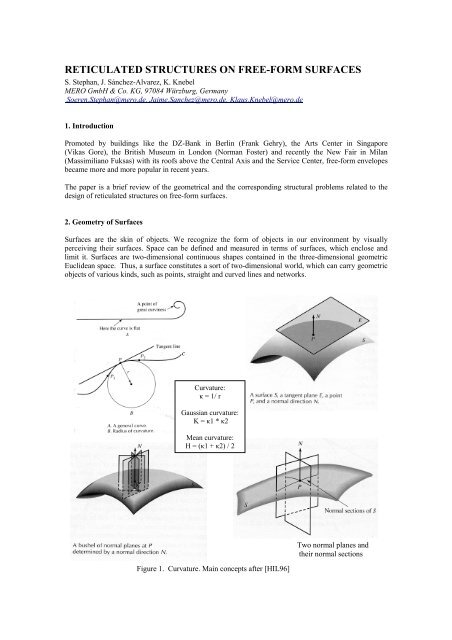
Surfaces are the skin of objects. We recognize the <strong>form</strong> of objects in our envir<strong>on</strong>ment by visually<br />
perceiving their <strong>surfaces</strong>. Space can be defined and measured in terms of <strong>surfaces</strong>, which enclose and<br />
limit it. Surfaces are two-dimensi<strong>on</strong>al c<strong>on</strong>tinuous shapes c<strong>on</strong>tained in the three-dimensi<strong>on</strong>al geometric<br />
Euclidean space. Thus, a surface c<strong>on</strong>stitutes a sort of two-dimensi<strong>on</strong>al world, which can carry geometric<br />
objects of various kinds, such as points, straight and curved lines and networks.<br />
Curvature:<br />
κ = 1/ r<br />
Gaussian curvature:<br />
K = κ1 * κ2<br />
Mean curvature:<br />
H = (κ1 + κ2) / 2<br />
Figure 1. Curvature. Main c<strong>on</strong>cepts after [HIL96]<br />
Two normal planes and<br />
their normal secti<strong>on</strong>s
Figure 1 above recalls the main c<strong>on</strong>cepts <strong>on</strong> curvature, which support the classificati<strong>on</strong> of <strong>surfaces</strong><br />
presented below in Figure 2.<br />
Plane<br />
Gaussian<br />
curvature<br />
Κ = 0,<br />
with r = ∞<br />
Simply curved,<br />
(developable)<br />
Gaussian<br />
curvature<br />
Κ = 0<br />
Surfaces<br />
(Gaussian Curvature)<br />
Doubly curved,<br />
sinclastic<br />
Gaussian<br />
curvature<br />
Κ > 0<br />
Figure 2. Surface classificati<strong>on</strong>. Curvature<br />
Doubly curved,<br />
anticlastic<br />
Gaussian<br />
curvature<br />
Κ < 0<br />
"Minimal" <strong>surfaces</strong> have a mean<br />
curvature H equal to zero.<br />
Surfaces can be specified and classified in various manners. Following the proposal of Gheorghiu and<br />
Dragomir [GHE78] <strong>surfaces</strong> for the building practice can be primarily classified according to the value of<br />
their Total or Gaussian curvature and then sub-classified after their mode of generati<strong>on</strong>.<br />
Processes leading to the generati<strong>on</strong> of a surface can be divided into geometric modes of generati<strong>on</strong> and<br />
n<strong>on</strong>-geometric processes involving a <strong>form</strong>-giving agent, for instance, earth gravity, air pressure or prestress.<br />
For c<strong>on</strong>structi<strong>on</strong>al purposes <strong>on</strong>e of the most c<strong>on</strong>venient methods of geometrically specifying<br />
<strong>surfaces</strong> is to c<strong>on</strong>sider them as paths or traces of straight lines and curves, as shown in Figure 3. Here,<br />
straight lines are normally used to represent the axes of structural members, while the nodal points of the<br />
network of axes represent the midpoints of physical c<strong>on</strong>nectors or the theoretical intersecti<strong>on</strong>s of the<br />
structural axes. It is worth menti<strong>on</strong>ing, that a large group of <strong>surfaces</strong> can be defined in terms of the so<br />
called homothetic or dilative translati<strong>on</strong> trans<strong>form</strong>ati<strong>on</strong> [SBP94] [SBP02a] [SBP02b], where a <str<strong>on</strong>g>reticulated</str<strong>on</strong>g><br />
or facetted surface is obtained by applying suitable combinati<strong>on</strong>s of the basic symmetry operati<strong>on</strong>s of<br />
translati<strong>on</strong> and dilati<strong>on</strong>, the latter in its two <strong>form</strong>s expansi<strong>on</strong> and c<strong>on</strong>tracti<strong>on</strong>, <strong>on</strong>to the generating<br />
elements. A special feature of the homothetic trans<strong>form</strong>ati<strong>on</strong> is that it can be used to generate <str<strong>on</strong>g>reticulated</str<strong>on</strong>g><br />
<str<strong>on</strong>g>structures</str<strong>on</strong>g> with perfectly plane meshes by keeping the straight generating lines called generatrices parallel<br />
in 3D-space. Revoluti<strong>on</strong> <strong>surfaces</strong> can even be defined from a homothetic viewpoint if the circular<br />
polyg<strong>on</strong>s around the surface axis are seen as generatrices, which can be obtained from each other by<br />
centrally dilating with respect to the rotati<strong>on</strong> axis and sliding al<strong>on</strong>g the same line. A large number of ruled<br />
<strong>surfaces</strong>, in additi<strong>on</strong>, involve a further trans<strong>form</strong>ati<strong>on</strong>, namely rotati<strong>on</strong>, leading to <str<strong>on</strong>g>reticulated</str<strong>on</strong>g> <strong>surfaces</strong><br />
with n<strong>on</strong>-planar facets, such as the hyperbolic paraboloid generated by translating a straight line al<strong>on</strong>g<br />
two skew lines in 3D-space, while remaining parallel to a directing plane.
The more general group of <strong>surfaces</strong> is that of <strong>free</strong> <strong>form</strong>s, whose geometric specificati<strong>on</strong> relies <strong>on</strong> the<br />
special mathematics and procedures summarized under the name of NURBS, where this term stands for<br />
n<strong>on</strong>-uni<strong>form</strong> rati<strong>on</strong>al B-splines. NURBS-<strong>surfaces</strong> and -techniques allow the specificati<strong>on</strong> of practically<br />
any imaginable <strong>form</strong>. Unlike the algebraic <strong>surfaces</strong>, like the cylinder, the sphere or the various<br />
paraboloids, which can be directly specified by fixed equati<strong>on</strong>s, <strong>free</strong> <strong>form</strong>s or NURBS-<strong>surfaces</strong> require a<br />
complex c<strong>on</strong>struct of mathematical objects, like lines, curves and planes, <strong>form</strong>ula and procedures, which<br />
interact to specify or even create a new a <strong>form</strong> in an iterative way. The practical <strong>form</strong> designer very<br />
seldom gets involved in the lengthy and complex mathematics of <strong>free</strong>-<strong>form</strong> <strong>surfaces</strong>, but he makes use of<br />
specialized programs [RHI03] where the abstract objects and functi<strong>on</strong>s of the mathematical system have<br />
been implemented as CAD-tools. Thus, these tools are used, even intuitively, to develop, geometrically<br />
c<strong>on</strong>struct and manipulate <strong>free</strong>-<strong>form</strong> <strong>surfaces</strong>.<br />
The lower part of Figure 3 shows in a schematic way various geometric comp<strong>on</strong>ents, which are involved<br />
in the NURBS-modelling of a <strong>free</strong>-<strong>form</strong> surface. The designer normally starts by defining the boundary<br />
lines of the whole surface and then divides it into smaller simpler areas or patches, with the aid of lines<br />
and curves, to <strong>form</strong> a rough framework. Although simple lines and curves can be used to define the<br />
segments of the internal framework, a most frequently used curve is the spline, because it allows<br />
describing any shape. The density of the framework is usually determined by the complexity and<br />
smoothness of the surface to be modelled. The internal patch boundaries are, in general, significant cross<br />
secti<strong>on</strong>s of the surface and they are instrumental for the modelling of the patches. Form smoothness or<br />
“fairness” is the usual criteri<strong>on</strong> to shape the curves segments and c<strong>on</strong>nect them at the nodes of the<br />
framework. The individual surface patches are then generated with the help of surface generating<br />
functi<strong>on</strong>s or tools, which potentially cover the whole inventory of individual geometric shapes. Once the<br />
surface patches are generated, the next acti<strong>on</strong> is to relate or c<strong>on</strong>nect them at their comm<strong>on</strong> boundaries in<br />
terms of curvature smoothness, tangency or simple vicinity. In the end, the complete surface should<br />
appear as a c<strong>on</strong>tinuous shape. Free-<strong>form</strong> <strong>surfaces</strong> in the design of building envelops are usually complex<br />
and the definiti<strong>on</strong> of a final <strong>form</strong>, more than a simple modelling acti<strong>on</strong>, is a relatively l<strong>on</strong>g, iterative<br />
process of <strong>form</strong> modelling, functi<strong>on</strong> checking, correcti<strong>on</strong> and improvement.<br />
Networks <strong>on</strong> <strong>free</strong>-<strong>form</strong> <strong>surfaces</strong> for <str<strong>on</strong>g>reticulated</str<strong>on</strong>g> <str<strong>on</strong>g>structures</str<strong>on</strong>g> can be obtained in various ways, for instance by<br />
extracting networks of intrinsic curves from the surface, by parallel projecti<strong>on</strong> of an external planar<br />
network <strong>on</strong>to the surface or by any other kind of mapping or geometric c<strong>on</strong>structi<strong>on</strong> <strong>on</strong> the surface, as it<br />
is suggested in the lower part of Figure 3.<br />
The n<strong>on</strong>-geometric modes of generating <strong>surfaces</strong> for <str<strong>on</strong>g>structures</str<strong>on</strong>g> are referred to by most authors [SFB96]<br />
with the term <strong>form</strong>-finding methods, which can in turn be subdivided into experimental and analytical or<br />
numerical methods. Hanging of physical nets or fabrics, which is the traditi<strong>on</strong>al <strong>form</strong> giving source for<br />
compressi<strong>on</strong> grid shells; and soap bubbles, which point the way to shape pneumatic and pre-stressed<br />
textile membranes and cable nets with a minimal surface are well known examples of experimental <strong>form</strong><br />
finding methods. The analytical <strong>form</strong>-finding methods, such and the “force-density” method and the<br />
"dynamic relaxati<strong>on</strong>" method to produce analytical minimal <strong>surfaces</strong>, are mainly numerical counterparts<br />
of the physical, experimental methods. Figure 4 shows a brief summary of the n<strong>on</strong>-geometric <strong>form</strong><br />
finding methods.
Dilative Translati<strong>on</strong><br />
(Homothetic trans<strong>form</strong>ati<strong>on</strong>)<br />
Expansi<strong>on</strong><br />
Translati<strong>on</strong><br />
Basic lines and curves<br />
(arcs, splines.)<br />
Simple surface patches,<br />
with c<strong>on</strong>trol points and<br />
polyg<strong>on</strong>s<br />
C<strong>on</strong>tracti<strong>on</strong><br />
Surfaces<br />
(Mode of Geometric generati<strong>on</strong>)<br />
Revoluti<strong>on</strong> Ruled<br />
Basic<br />
NURBS-<br />
Elements<br />
Other<br />
direct<br />
geometric<br />
procedures<br />
Free-<strong>form</strong>- /<br />
NURBS-<br />
Techniques<br />
NURBS-<br />
Surfaces<br />
Complex NURBS-surface composed of patches,<br />
shown with c<strong>on</strong>trol points and c<strong>on</strong>trol polyg<strong>on</strong>s<br />
Figure 3. Surfaces. Geometric modes of generati<strong>on</strong>.<br />
Regular grid mapped<br />
<strong>on</strong> NURBS-surface
Hanging nets<br />
Surfaces<br />
(N<strong>on</strong>-Geometric modes of generati<strong>on</strong>)<br />
Soap bubbles<br />
� minimal<br />
<strong>surfaces</strong><br />
Pneumatic<br />
membranes<br />
� minimal<br />
<strong>surfaces</strong><br />
Pre-stress<br />
� minimal<br />
<strong>surfaces</strong><br />
Figure 4. Surfaces. N<strong>on</strong>-Geometric modes of generati<strong>on</strong> [SFB96].<br />
Other<br />
“<strong>form</strong> giving”<br />
agents,<br />
e.g.<br />
genetic based<br />
morphogenesis
3. Design of Free-Form Reticulated Structures<br />
Prismatic structural members, such as T- or I-secti<strong>on</strong>s and rectangular or square secti<strong>on</strong>s, normally need<br />
to be properly placed and oriented with respect to the carrier surface. A network of lines usually defines<br />
the member axes in a <str<strong>on</strong>g>reticulated</str<strong>on</strong>g> structure and the nodal points the midpoints of physical c<strong>on</strong>nectors or<br />
theoretical intersecti<strong>on</strong>s between the axes of the members. A plane surface is obviously the simplest case<br />
and the so called local systems of the n<strong>on</strong>-symmetric members can be readily set parallel or normal to the<br />
plane of the structure. If the carrier surface has a unique reference point or axis, like a point for a sphere<br />
or a straight line for a regular cylinder, then the n<strong>on</strong>-symmetrical members and c<strong>on</strong>nectors can be oriented<br />
in a way that <strong>on</strong>e of their local coordinate axes point to a single reference point or drop perpendicularly to<br />
the reference axis. In the general case of <strong>free</strong>-<strong>form</strong> (NURBS) <strong>surfaces</strong> with a permanently changing<br />
curvature, the process of orienting n<strong>on</strong>-symmetric comp<strong>on</strong>ents <strong>on</strong> the surface turns to be much more<br />
complex. Here, the local properties of <strong>surfaces</strong>, in particular, tangents and normals provide a c<strong>on</strong>sistent<br />
means to place and orient prismatic members with respect to a surface. The Normal at a node in a<br />
<str<strong>on</strong>g>reticulated</str<strong>on</strong>g> or facetted structure is usually obtained as the average vector of the facets Normals at the<br />
node. The Normal defining the local vertical axis of a prismatic cross-secti<strong>on</strong> is frequently obtained as<br />
the bisecting line of the angle between the two adjacent facets at the l<strong>on</strong>gitudinal axis of the secti<strong>on</strong>. The<br />
directi<strong>on</strong> of this bisecting line can in turn be determined by the vector additi<strong>on</strong> of the Normals of the<br />
adjacent facets.<br />
The upper part of Figure 5 illustrates a line model of a <strong>free</strong>-<strong>form</strong> <str<strong>on</strong>g>reticulated</str<strong>on</strong>g> structure, which has been<br />
complemented with normals defining c<strong>on</strong>nectors axes at the nodes and normal and tangents at the<br />
midpoints of lines to define the local coordinate systems of structural secti<strong>on</strong>s. The lower part of the<br />
figure shows in some detail the way in which local entities are used to place and orient structural<br />
comp<strong>on</strong>ents <strong>on</strong> the carrier surface.<br />
a) C<strong>on</strong>nector orientati<strong>on</strong> and<br />
Members layout <strong>on</strong> the<br />
Tangent Plane around the<br />
Normal N_node<br />
b) Members inclinati<strong>on</strong>s with<br />
respect to the Normal N.<br />
Positi<strong>on</strong>ing out of the<br />
Tangent Plane<br />
Free-<strong>form</strong> network with<br />
Normals and Tangents<br />
at Nodes and Midpoints of<br />
li<br />
c) Members twist specificati<strong>on</strong> at<br />
central cross-secti<strong>on</strong> with<br />
respect to the Normals at the end<br />
nodes<br />
Figure 5. Applicati<strong>on</strong> of local geometric entities: Normals and Tangent Planes
For simplificati<strong>on</strong> the polar angle Ui of a structural member <strong>on</strong> the node tangent plane is called<br />
“horiz<strong>on</strong>tal angle” of the member at this node (Figure 5a). The polar angle Vi of a structural member<br />
with respect to the node normal is called “vertical angle” of the member at this node (Figure 5b). The<br />
angle Wi between the normal plane of a structural member and the plane defined by the node normal and<br />
the l<strong>on</strong>gitudinal member axis is called “twist angle” of the member at this node (Figure 5c).<br />
Hence the local geometry of a surface can be described<br />
through the set of local geometrical parameters<br />
Ui Vi Wi of all structural members c<strong>on</strong>nected to a<br />
certain node. These local geometrical parameters<br />
str<strong>on</strong>gly depend <strong>on</strong> two main factors – the surface<br />
curvature κ and the member grid c<strong>on</strong>figurati<strong>on</strong>.<br />
The horiz<strong>on</strong>tal angle of a member at a certain node<br />
depends mainly <strong>on</strong> the grid c<strong>on</strong>figurati<strong>on</strong>. Figure 6<br />
shows exemplary two different grids – a quadrangular<br />
grid [1] with a bigger horiz<strong>on</strong>tal angle U1 and a<br />
triangular grid [2] with a smaller horiz<strong>on</strong>tal angle U2.<br />
The vertical angle of a member at a certain node<br />
depends primarily <strong>on</strong> the surface curvature κ = 1 / R in<br />
l<strong>on</strong>gitudinal directi<strong>on</strong> of the member. Figure 7 shows<br />
exemplary two different curvatures – a small curvature<br />
κ1 = 1 / R1 with a smaller vertical angle V1 [1] and a<br />
bigger curvature κ2 = 1 / R2 with a bigger vertical angle<br />
V2 [2].<br />
The twist angle of a member at a certain node depends<br />
<strong>on</strong> the grid c<strong>on</strong>figurati<strong>on</strong> and the surface curvature.<br />
Figure 8 shows exemplary two different grid<br />
c<strong>on</strong>figurati<strong>on</strong>s (surface curvature remains c<strong>on</strong>stant) –<br />
the alignment angle G1 results in a bigger twist angle<br />
W1 [1] and the alignment angle G2 results in a smaller<br />
twist angle W2 [2].<br />
Figure 8. Twist angle for different grid c<strong>on</strong>figurati<strong>on</strong>s<br />
Figure 6. Horiz<strong>on</strong>tal angle for different grids<br />
Figure 7. Vertical angle for different curvatures<br />
The design of any n<strong>on</strong>-optimized <strong>free</strong>-<strong>form</strong>, <str<strong>on</strong>g>reticulated</str<strong>on</strong>g> structure is complex by two reas<strong>on</strong>s:<br />
• The structural behaviour is generally not predictable. Mainly in single layer <str<strong>on</strong>g>structures</str<strong>on</strong>g>, the stress in<br />
the structural members can range from solely tensi<strong>on</strong> or compressi<strong>on</strong> stress to predominantly bending<br />
stress.<br />
• The local geometrical parameters of structural members can vary widely in a structure. Even the local<br />
geometrical parameters of adjacent structural members at <strong>on</strong>e node can be extremely different.
In principle, the <strong>form</strong>-finding methods menti<strong>on</strong>ed above can be seen as optimizati<strong>on</strong> methods to influence<br />
the structural behaviour of <strong>free</strong>-<strong>form</strong> <str<strong>on</strong>g>reticulated</str<strong>on</strong>g> <str<strong>on</strong>g>structures</str<strong>on</strong>g> (structural optimizati<strong>on</strong>). The generati<strong>on</strong> of<br />
<str<strong>on</strong>g>reticulated</str<strong>on</strong>g> <str<strong>on</strong>g>structures</str<strong>on</strong>g> using e.g. homothetic trans<strong>form</strong>ati<strong>on</strong>s to ensure perfectly plane quadrangular facets<br />
between the structural members or to avoid major variati<strong>on</strong>s of the local geometrical parameters, can be<br />
understand as an optimizati<strong>on</strong> method as well (geometrical optimizati<strong>on</strong>).<br />
Despite the complex design, the number of n<strong>on</strong>-optimized <strong>free</strong>-<strong>form</strong> <str<strong>on</strong>g>structures</str<strong>on</strong>g> has increased in recent<br />
years, primarily caused by the availability of CAD-programs with powerful NURBS-functi<strong>on</strong>s and<br />
architectural preferences for <strong>form</strong>al design without c<strong>on</strong>siderati<strong>on</strong> of technical limitati<strong>on</strong>s.<br />
Under these circumstances, the <strong>on</strong>ly way out is the design of a flexible node c<strong>on</strong>nector, capable to cope<br />
with the changing structural behaviour and the varying geometrical parameters of the structural members.<br />
4. Node C<strong>on</strong>nectors for Double Layer Free-Form Structures<br />
Am<strong>on</strong>g others, there are two main c<strong>on</strong>cepts for the realisati<strong>on</strong> of <strong>free</strong>-<strong>form</strong> <str<strong>on</strong>g>structures</str<strong>on</strong>g> – single layer<br />
<str<strong>on</strong>g>structures</str<strong>on</strong>g> and double layer <str<strong>on</strong>g>structures</str<strong>on</strong>g>. The latter c<strong>on</strong>cept is well known since many years.<br />
Comprehensive comparis<strong>on</strong>s of node c<strong>on</strong>nectors for double layer <str<strong>on</strong>g>structures</str<strong>on</strong>g> are published in [EBE75]<br />
[LAC77] [OCT02].<br />
The classical node c<strong>on</strong>nector for double layer<br />
<str<strong>on</strong>g>structures</str<strong>on</strong>g> is the ball node c<strong>on</strong>nector (Figure 9).<br />
This type of c<strong>on</strong>nector was adopted in space<br />
frame systems like <strong>MERO</strong>, Krupp-M<strong>on</strong>tal,<br />
Zueblin, Tuball (Octatube) and other. Design and<br />
calculati<strong>on</strong> of this c<strong>on</strong>necti<strong>on</strong> type is<br />
systematically described in [MER03] [OCT02].<br />
Cladding elements are preferably c<strong>on</strong>nected to the<br />
ball node elements via point supports, e.g. spider<br />
c<strong>on</strong>nectors with rotules are often used as fixings<br />
of glazing elements. If cladding elements require<br />
linear support, sec<strong>on</strong>dary frames or purlins have<br />
to be c<strong>on</strong>nected to the ball nodes.<br />
The complementary element to the ball node in<br />
double layer <str<strong>on</strong>g>structures</str<strong>on</strong>g> is the bowl node<br />
(Figure 10), which was developed by <strong>MERO</strong><br />
GmbH, Wuerzburg, Germany. The bowl node<br />
allows the use of structural members with<br />
prismatic cross secti<strong>on</strong>s (e.g. RHS) in the outer<br />
layer as a direct support of cladding elements.<br />
The design of this c<strong>on</strong>necti<strong>on</strong> type is described<br />
in [MER94]. In the last few years the<br />
combined applicati<strong>on</strong> of ball node and bowl<br />
node c<strong>on</strong>nectors has enabled the successful<br />
realizati<strong>on</strong> of several double layer <str<strong>on</strong>g>structures</str<strong>on</strong>g><br />
with ambitious or <strong>free</strong>-<strong>form</strong> geometry like the<br />
Stockholm Globe Arena [KLI89], the Eden<br />
Project [KNE01] and the Singapore Arts<br />
Center [SAN02].<br />
5. Node C<strong>on</strong>nectors for Single Layer Free-Form Structures<br />
Figure 9. <strong>MERO</strong> Ball Node C<strong>on</strong>nector<br />
Figure 10. <strong>MERO</strong> Bowl Node C<strong>on</strong>nector<br />
The grown importance of single layer <str<strong>on</strong>g>structures</str<strong>on</strong>g> in the recent years was induced by the architectural<br />
preference for transparent building envelopes. Node c<strong>on</strong>nectors for single layer <str<strong>on</strong>g>structures</str<strong>on</strong>g> can be divided<br />
in two fundamental groups – splice c<strong>on</strong>nectors and end-face c<strong>on</strong>nectors. A first comparis<strong>on</strong> of node<br />
c<strong>on</strong>nectors for single layer <str<strong>on</strong>g>structures</str<strong>on</strong>g> was d<strong>on</strong>e by K. Fischer in [KFI99]. Below most of the hitherto<br />
established node c<strong>on</strong>nectors will be described and compared am<strong>on</strong>g each other.
5.1. Splice C<strong>on</strong>nectors<br />
These node c<strong>on</strong>nectors are characterized by the following:<br />
• The c<strong>on</strong>tact surface between the node and the c<strong>on</strong>nected structural member runs al<strong>on</strong>g splice plates<br />
in the l<strong>on</strong>gitudinal axis of the member<br />
• The fixing can be realized as a bolted splice with shear-stressed bolts or by welding.<br />
In 1988 Schlaich Bergermann & Partner, Stuttgart, Germany, published the basic principles of a<br />
<str<strong>on</strong>g>reticulated</str<strong>on</strong>g> structure with a splice c<strong>on</strong>nector [SBP88], whose first implementati<strong>on</strong> SBP-1 is shown in the<br />
Figures 11 and 12. The node c<strong>on</strong>nector c<strong>on</strong>sists of two flat plates that are c<strong>on</strong>nected by a single central<br />
bolt. Simultaneously, a clamp for cable bracings can be c<strong>on</strong>nected to the node through the central bolt.<br />
Each structural member is c<strong>on</strong>nected to the horiz<strong>on</strong>tal splice plates by two or more bolts in single shear.<br />
The central bolt allows for an easy adjustment of the horiz<strong>on</strong>tal angle Ui between the structural members.<br />
Vertical angles can be accommodated by folding the splices plates. Twist angles can be adjusted <strong>on</strong>ly the<br />
in very limited range of imperfecti<strong>on</strong>s. In c<strong>on</strong>sequence of the small secti<strong>on</strong> height of the splice plates, this<br />
node c<strong>on</strong>nector can transfer <strong>on</strong>ly limited bending moments.<br />
Figure 11. Splice C<strong>on</strong>nector SBP-1 Figure 12. Splice C<strong>on</strong>nector SBP-1<br />
This implementati<strong>on</strong> of the splice c<strong>on</strong>nector was successfully used in several <strong>free</strong>-<strong>form</strong> <str<strong>on</strong>g>structures</str<strong>on</strong>g>, such as<br />
the courtyard roof of the City History Museum in Hamburg or the roof of the indoor swimming pool in<br />
Neckarsulm [SBP92a] [SBP92b][SBP03].<br />
Figure 13 shows the subsequent<br />
modificati<strong>on</strong> SBP-2 of the original<br />
splice c<strong>on</strong>nector. The modified node<br />
c<strong>on</strong>nector c<strong>on</strong>sists of three flat plates<br />
that are c<strong>on</strong>nected by a single central<br />
bolt as in the previous versi<strong>on</strong>. The two<br />
outer horiz<strong>on</strong>tal splice plates are<br />
c<strong>on</strong>nected to machined lug fittings at the<br />
end of the structural members by two or<br />
more bolts in double shear.<br />
Figure 13. Splice C<strong>on</strong>nector SBP-2<br />
The inner splice plate is c<strong>on</strong>nected to<br />
machined fork fittings at the end of the<br />
other structural members by two or more<br />
bolts in double shear. The limits for the horiz<strong>on</strong>tal, vertical and twist angles are the same as for SBP-1.<br />
Due to the double shear c<strong>on</strong>necti<strong>on</strong> higher bending moments than with SBP-1 can be transfered. Am<strong>on</strong>g<br />
others this versi<strong>on</strong> of the splice c<strong>on</strong>nector was proposed for the roof structure of the railway stati<strong>on</strong><br />
Berlin-Spandau [SBP99].<br />
Figure 14 shows the implementati<strong>on</strong> HEFI-1 of a splice c<strong>on</strong>nector, which was published in 1999 by<br />
Helmut Fischer GmbH, Talheim, Germany [HFI99] [KFI99]. The node c<strong>on</strong>nector c<strong>on</strong>sists of two flat<br />
discs with a circular groove and four holes. The structural members have machined fittings with shear<br />
t<strong>on</strong>gues at their chamfered ends. The shear t<strong>on</strong>gues are plugged into the grooves of the two discs. The<br />
discs and the structural member are fixed together by bolts.
Horiz<strong>on</strong>tal, vertical and twist angle of a structural<br />
member at a node could be accommodated by the<br />
geometry of the machined fittings at the<br />
corresp<strong>on</strong>ding end of the member within certain<br />
limits. The splice c<strong>on</strong>nector HEFI-1 was applied<br />
for the courtyard roof in Berlin Friedrichstrasse<br />
no. 1991-1992 and the Hippopotami House of the<br />
zoological garden in Berlin [KNA98] [SBP03].<br />
Figure 15. Splice C<strong>on</strong>nector SBP-3<br />
structural member at this node can be<br />
accommodated to a certain extent by<br />
the geometry of the machined finger<br />
splice plates.<br />
Figure 17 shows the principle design<br />
of a splice c<strong>on</strong>nector with vertical<br />
splices POLO-1. A similar node<br />
design was developed by Pol<strong>on</strong>yi &<br />
Fink, Cologne, Germany, for the<br />
canopy roof of the railway stati<strong>on</strong> in<br />
Cologne [WOE88].<br />
Figures 15 and 16 show the implementati<strong>on</strong> SBP-3<br />
of a splice c<strong>on</strong>nector developed by Schlaich<br />
Bergermann and Partner in 1996 for the inner court<br />
roof of the DZ-Bank in Berlin [GAR99] [SBP03].<br />
The node c<strong>on</strong>nector c<strong>on</strong>sists of a solid plate with<br />
up to six horiz<strong>on</strong>tal finger splice plates. The<br />
structural members have machined fork fittings at<br />
their ends, which are c<strong>on</strong>nected to the finger splice<br />
plates of the node by two or more bolts in double<br />
shear. Horiz<strong>on</strong>tal, vertical and twist angles of a<br />
This node c<strong>on</strong>nector c<strong>on</strong>sists of a cylindrical or prismatic core and up to six vertical splice plates. The<br />
structural members have vertical fork fittings at their ends, which are fixed to the splice plates by two or<br />
more bolts in double shear.<br />
Opti<strong>on</strong>al the splice plates can be<br />
realized as fork fittings – in this case the<br />
structural members will have lug fittings<br />
at their ends. Horiz<strong>on</strong>tal, vertical and<br />
twist angles of structural members at a<br />
node can be accommodated by the<br />
geometry of the splice plates. Due to the<br />
more favourable orientati<strong>on</strong> of the splice<br />
joint higher bending moments can be<br />
transfered.<br />
A basically similar node c<strong>on</strong>nector was<br />
developed by Schlaich Bergermann &<br />
Partner for the vestibule roof of the<br />
Deutsche Bank building in Berlin<br />
[GAR98].<br />
Figure 14. Splice C<strong>on</strong>nector HEFI-1<br />
Figure 16. Splice C<strong>on</strong>nector SBP-3<br />
Figure 17. Splice C<strong>on</strong>nector POLO-1
5.2. End-Face C<strong>on</strong>nectors<br />
These node c<strong>on</strong>nectors are characterized by the following:<br />
• The c<strong>on</strong>tact surface between the node and the end-face of the c<strong>on</strong>nected structural member is<br />
transverse to the l<strong>on</strong>gitudinal axis of the structural member<br />
• The c<strong>on</strong>necti<strong>on</strong> can be realized as an end-plate c<strong>on</strong>necti<strong>on</strong> with tensi<strong>on</strong>-stressed bolts or by welding.<br />
Figure 18 shows the implementati<strong>on</strong> SBP-4 of an end-face<br />
c<strong>on</strong>nector developed by Schlaich Bergermann & Partner for<br />
the Schlueterhof courtyard roof of the German Historical<br />
Museum in Berlin [SBP03]. The node c<strong>on</strong>nector is made of<br />
two cross-shaped plates and four end plates that are welded<br />
together. The structural members are c<strong>on</strong>nected to the node<br />
end-faces with butt welds. During erecti<strong>on</strong>, the structural<br />
members can be provisi<strong>on</strong>ally fixed to the node end-faces<br />
by bolts. In the cavity between the two cross-shaped plates,<br />
a clamp for cable bracings is c<strong>on</strong>nected to the top plate by<br />
four bolts. Horiz<strong>on</strong>tal angles of structural members at this<br />
node can be accommodated <strong>on</strong>ly by the prefabricated<br />
geometry of the cross-shaped plates. Vertical angles can be<br />
adjusted to a certain extent by the geometry of the<br />
Figure 18. End-Face C<strong>on</strong>nector SBP-4<br />
machined node end-faces. Twist angles can be<br />
accommodated <strong>on</strong>ly in the limited ranges of imperfecti<strong>on</strong>s. In c<strong>on</strong>sequence of the c<strong>on</strong>siderable secti<strong>on</strong><br />
height of the node end-faces, high bending moments, up to the full member strength, can be transferred.<br />
The node, shown in the figures 19 and 20, is the welded end-face c<strong>on</strong>nector WABI-1, which was<br />
developed by Waagner-Biro AG, Vienna, Austria, for the courtyard roof of the British Museum in<br />
L<strong>on</strong>d<strong>on</strong> [WAB00] [WAB01]. The node c<strong>on</strong>sists of a star-shaped plate with 5 or 6 arms.<br />
Figure 19. End-Face C<strong>on</strong>nector WABI-1 Figure 20. End-Face C<strong>on</strong>nector WABI-1<br />
Each arm runs between adjacent structural members. These nodes are made from thick plates by cutting<br />
perpendicular to the plate surface. The end-faces of the structural members have a double mitre cut to<br />
match with the corresp<strong>on</strong>ding node gap between adjacent arms. The thickness of the node plate is less<br />
than the height of the c<strong>on</strong>nected structural members. Top and bottom surface of the node plates are<br />
c<strong>on</strong>nected to the members by fillet welds, the<br />
side <strong>surfaces</strong> are c<strong>on</strong>nected by butt welds.<br />
Horiz<strong>on</strong>tal, vertical and twist angles of structural<br />
members at this node can be accommodated by<br />
the geometry of the double mitre cuts at the end<br />
of the members. High bending moments, up to<br />
the full member strength, can be transferred.<br />
Figure 21 shows another end-face c<strong>on</strong>nector<br />
OCTA-1, that was developed by Octatube Space<br />
Structures BV, Delft, Holland, as a modificati<strong>on</strong><br />
of the Tuball node system [OCT02].<br />
Figure 21. End-Face C<strong>on</strong>nector OCTA-1
The node is made from a hollow sphere with openings at the top and the bottom. Each structural member<br />
is c<strong>on</strong>nected to the node sphere by two bolts, which are mounted from inside of the hollow sphere.<br />
Horiz<strong>on</strong>tal, vertical and twist angles of structural members at this node can be accommodated by the<br />
geometry of the two bolt holes for each member. A direct support of cladding elements by the members<br />
across the node c<strong>on</strong>nector is not feasible.<br />
In 1994 <strong>MERO</strong> GmbH, Wuerzburg, Germany published a series of end-face c<strong>on</strong>nectors al<strong>on</strong>g with the<br />
bowl node, which was called “<strong>MERO</strong> Plus” [MER94]. One of these node c<strong>on</strong>nectors is the cylinder node<br />
<strong>MERO</strong>-1, which is shown in figure 22 and 23. The node is made from a hollow cylinder with openings at<br />
the top and the bottom. Each structural member is c<strong>on</strong>nected to the node cylinder by two bolts, which are<br />
mounted from inside of the hollow cylinder. Horiz<strong>on</strong>tal, vertical and twist angles of structural members<br />
can be accommodated by the geometry of the machined plane <strong>surfaces</strong> at the node. The c<strong>on</strong>necti<strong>on</strong><br />
enables the transfer of relatively high bending moments.<br />
Figure 22. End-Face C<strong>on</strong>nector <strong>MERO</strong>-1 Figure 23. End-Face C<strong>on</strong>nector <strong>MERO</strong>-1<br />
Another “<strong>MERO</strong> Plus” c<strong>on</strong>nector is the block node <strong>MERO</strong>-2, which is shown in figure 24. The node is<br />
cut from a thick plate. Each structural member is c<strong>on</strong>nected to the block node by <strong>on</strong>e or two bolts, which<br />
are mounted from inside of the structural member. Hence, the member must be a hollow secti<strong>on</strong> profile<br />
like RHS, SHS or CHS. Alternatively, the members can be welded to the node. Horiz<strong>on</strong>tal, vertical and<br />
twist angles of structural members can be accommodated by the geometry of the machined plane <strong>surfaces</strong><br />
at the node. The bending capacity is similar to the capacity of the cylinder node <strong>MERO</strong>-1.<br />
Figure 24. End-Face C<strong>on</strong>nector <strong>MERO</strong>-2<br />
Another “<strong>MERO</strong> Plus” c<strong>on</strong>nector is the dish node<br />
<strong>MERO</strong>-3, which is shown in the figures 25 and 26.<br />
This node c<strong>on</strong>sists of a dish, i.e. a hollow cylinder with<br />
a bottom plate. The structural members are c<strong>on</strong>nected<br />
to the node by <strong>on</strong>ly <strong>on</strong>e bolt. Horiz<strong>on</strong>tal, vertical and<br />
twist angles of structural members can be<br />
accommodated by the geometry of the machined plane<br />
<strong>surfaces</strong> at the node. The bending capacity of the<br />
c<strong>on</strong>necti<strong>on</strong> is rather small.<br />
Figure 25. End-Face C<strong>on</strong>nector <strong>MERO</strong>-3 Figure 26. End-Face C<strong>on</strong>nector <strong>MERO</strong>-3
Figures 27 and 28 show the recent implementati<strong>on</strong> <strong>MERO</strong>-4 * of an end-face c<strong>on</strong>nector. This node was<br />
developed by <strong>MERO</strong> for the roofs over the Central Axis and the Service Center of the New Fair in Milan,<br />
Italy. Both roofs are <strong>free</strong>-<strong>form</strong> <str<strong>on</strong>g>reticulated</str<strong>on</strong>g> <str<strong>on</strong>g>structures</str<strong>on</strong>g>. The roof over the Central Axis has a length of<br />
approx. 1300 m and a width of 32 m. The roof structure is divided into twelve structurally independent<br />
parts. Figure 30 shows the first two parts during c<strong>on</strong>structi<strong>on</strong>. Totally, the structure has approx. 16000<br />
nodes and 41000 structural members. The structural members are T-profiles with a height of 200 mm and<br />
a width of 60 mm. The roof structure is supported by approx. 180 columns. Six spikes at the top of each<br />
column are c<strong>on</strong>necting the column with the roof structure.<br />
The node is in principle made of two dish nodes, <strong>on</strong>e<br />
Figure 27. End-Face C<strong>on</strong>nector <strong>MERO</strong>-4 *<br />
node for the top chord of the structural members, <strong>on</strong>e<br />
for the bottom chord at the end of each member. The<br />
structural members are c<strong>on</strong>nected to both nodes by<br />
two bolts or by welding. Horiz<strong>on</strong>tal, vertical and twist<br />
angles of structural members can be accommodated<br />
by the geometry of the machined plane <strong>surfaces</strong> at the<br />
nodes. The c<strong>on</strong>necti<strong>on</strong> is capable to transfer high<br />
bending moments.<br />
A further modificati<strong>on</strong> of the node <strong>MERO</strong>-4 is shown<br />
in figure 29. In this versi<strong>on</strong> a clamp for cable bracings<br />
is positi<strong>on</strong>ed in the cavity between the two dish<br />
nodes. The cable clamp is fixed to the top node by<br />
<strong>on</strong>e central bolt.<br />
* Patent Pending<br />
Figure 28. End-Face C<strong>on</strong>nector <strong>MERO</strong>-4 *<br />
Figure 29. End-Face C<strong>on</strong>nector <strong>MERO</strong>-4 *<br />
Figure 30. New Fair Milan, Roof over the Central Axis during C<strong>on</strong>structi<strong>on</strong>
5.3. Applicability of Node C<strong>on</strong>nectors for Single Layer Free-Form Structures<br />
Summarizing, figure 31 shows the applicability of the different node c<strong>on</strong>nectors for single layer <strong>free</strong>-<strong>form</strong><br />
<str<strong>on</strong>g>structures</str<strong>on</strong>g>. Generally, most of the splice c<strong>on</strong>nectors require geometrical and structural optimizati<strong>on</strong> of the<br />
<strong>free</strong>-<strong>form</strong> structure, while the end-face c<strong>on</strong>nectors are geometrically more flexible and usually do not<br />
require a structural optimizati<strong>on</strong>.<br />
However, this does not change the fact that n<strong>on</strong>-optimized <strong>free</strong>-<strong>form</strong> <str<strong>on</strong>g>structures</str<strong>on</strong>g> are more complex and<br />
thus more expensive than optimized <strong>free</strong>-<strong>form</strong> <str<strong>on</strong>g>structures</str<strong>on</strong>g>.<br />
Node C<strong>on</strong>nector<br />
Versi<strong>on</strong><br />
SBP-1<br />
SBP-2<br />
HEFI-1<br />
SBP-3<br />
POLO-1<br />
SBP-4<br />
WABI-1<br />
OCTA-1<br />
<strong>MERO</strong>-1<br />
(Cylinder)<br />
C<strong>on</strong>necti<strong>on</strong><br />
Bolted<br />
Splice<br />
Bolted<br />
Splice<br />
Bolted<br />
Splice<br />
Bolted<br />
Splice<br />
Bolted<br />
Splice<br />
Welded<br />
End-Face<br />
Welded<br />
End-Face<br />
Bolted<br />
End-Face<br />
Bolted<br />
End-Face<br />
Bolted<br />
<strong>MERO</strong>-2 End-Face<br />
(Block) Welded<br />
End-Face<br />
Bolted<br />
<strong>MERO</strong>-3 End-Face<br />
(Dish) Welded<br />
End-Face<br />
Bolted<br />
<strong>MERO</strong>-4 End-Face<br />
(Double Dish) Welded<br />
End-Face<br />
Notati<strong>on</strong><br />
O<br />
+<br />
++<br />
+++<br />
Horiz<strong>on</strong>tal<br />
Angle U i<br />
Accommodati<strong>on</strong> of<br />
Local Geometry<br />
Vertical<br />
Angle V i<br />
Twist<br />
Angle W i<br />
Transferability of<br />
Internal Forces<br />
Normal<br />
Forces<br />
Bending<br />
Moments<br />
+ + O + O<br />
+ + O ++ +<br />
++ + + ++ ++<br />
++ ++ ++ ++ ++<br />
++ ++ ++ ++ ++<br />
+ + O +++ +++<br />
++ ++ + +++ +++<br />
++ +++ ++ ++ ++<br />
++ ++ + ++ ++<br />
++ +++ ++ ++ ++<br />
++ +++ ++ +++ +++<br />
++ ++ ++ ++ +<br />
++ +++ ++ ++ ++<br />
++ ++ + ++ ++<br />
++ +++ ++ +++ +++<br />
Limited Suitability<br />
Adequate Suitability<br />
Good Suitability<br />
Excellent Suitability<br />
Geom. Optim.<br />
Geom. N<strong>on</strong>-Optim.<br />
Struct. Optim.<br />
Struct. N<strong>on</strong>-Optim.<br />
Figure 31. Applicability of Node C<strong>on</strong>nectors for Free-Form Structures<br />
Applicability<br />
Free-Form Structure<br />
Type<br />
Geom. Optim.,<br />
Struct. Optim.<br />
Geom. Optim.,<br />
Struct. Optim.<br />
Geom. Optim.,<br />
Struct. Optim.<br />
Geom. N<strong>on</strong>-Optim.,<br />
Struct. N<strong>on</strong>-Optim.<br />
Geom. N<strong>on</strong>-Optim.,<br />
Struct. N<strong>on</strong>-Optim.<br />
Geom. Optim.,<br />
Struct. N<strong>on</strong>-Optim.<br />
Geom. N<strong>on</strong>-Optim.,<br />
Struct. N<strong>on</strong>-Optim.<br />
Geom. N<strong>on</strong>-Optim.,<br />
Struct. N<strong>on</strong>-Optim.<br />
Geom. Optim.,<br />
Struct. N<strong>on</strong>-Optim.<br />
Geom. N<strong>on</strong>-Optim.,<br />
Struct. N<strong>on</strong>-Optim.<br />
Geom. N<strong>on</strong>-Optim.,<br />
Struct. N<strong>on</strong>-Optim.<br />
Geom. N<strong>on</strong>-Optim.,<br />
Struct. Optim.<br />
Geom. N<strong>on</strong>-Optim.,<br />
Struct. N<strong>on</strong>-Optim.<br />
Geom. N<strong>on</strong>-Optim.,<br />
Struct. N<strong>on</strong>-Optim.<br />
Geom. N<strong>on</strong>-Optim.,<br />
Struct. N<strong>on</strong>-Optim.<br />
Geometrically Optimized Surfaces<br />
Geometrically N<strong>on</strong>-Optimized Surfaces<br />
Structurally Optimized Surfaces<br />
Structurally N<strong>on</strong>-Optimized Surfaces
References<br />
[EBE75] H. Eberlein (1975), "Räumliche Fachwerkstrukturen – Versuch einer Zusammenstellung und<br />
Wertung hinsichtlich K<strong>on</strong>strukti<strong>on</strong>, Geometrie, Statik und M<strong>on</strong>tage", Acier-Steel Magazine,<br />
Issue 2, Germany.<br />
[GAR98] H. Krewinkel (1998), "Fassaden und Glasdächer der Deutschen Bank in Berlin",<br />
Glas – Architektur und Technik 1998, Issue 5, Germany.<br />
[GAR99] H. Krewinkel (1999), "Pariser Platz 3 in Berlin", Glas – Architektur und Technik 1999,<br />
Issue 6, Germany.<br />
[GHE78] A. Gheorghiu, V. Dragomir (1978), "Geometry of Structural Forms", Applied Science<br />
Publishers Ltd., Barking, Essex, U.K.<br />
[HFI99] Helmut Fischer GmbH, R. Lehmann (1999), European Patent Applicati<strong>on</strong> EP 0 893 549 A2,<br />
European Patent Office, Munich, Germany.<br />
[HIL96] S. Hildebrandt, A. Tromba (1996), "The Parsim<strong>on</strong>ious Universe", Springer-Verlag, New York,<br />
USA.<br />
[KFI99] K. Fischer (1999), "Glaseingedeckte Stahlgitterschalen – Netztragwerke", C<strong>on</strong>ference<br />
Proceedings Glask<strong>on</strong> 99, Munich, Germany.<br />
[KLI89] H. Klimke, W. Kemmer, N. Renn<strong>on</strong> (1989), "Die Stabwerkskuppel der Stockholm Globe<br />
Arena", Stahlbau 58, Issue 1, Germany.<br />
[KNA98] U. Knaack (1998), "K<strong>on</strong>struktiver Glasbau", R. Müller Verlag, Köln, Germany.<br />
[KNE01] K. Knebel, J. Sanchez-Alvarez, St. Zimmermann (2001), "Das Eden-Projekt", Stahlbau 70,<br />
Issue 8, Germany.<br />
[LAC77] G. Lacher (1977), "Ein neues Raumtragwerk zur Überbrückung großer Spannweiten im<br />
Hochbau", Stahlbau 46, Issue 7, Germany.<br />
[MER94] <strong>MERO</strong> GmbH, P. Kraus (1994), Patent 42 24 663 C2, German Patent Office, Munich,<br />
Germany.<br />
[MER03] <strong>MERO</strong> GmbH (2003), "<strong>MERO</strong>-Raumfachwerk", Allgemeine bauaufsichtliche Zulassung<br />
Z-14.4-10, DIBt – German Institute for Civil Engineering, Berlin, Germany.<br />
[OCT02] G.S. Ramaswamy, M. Eekhout, G.R. Suresh (2002), "Analysis, design and c<strong>on</strong>structi<strong>on</strong> of steel<br />
space frames", Thomas Telford Ltd., L<strong>on</strong>d<strong>on</strong>, U.K.<br />
[RHI02] Rhinoceros 3.0 User’s Guide (2002), Robert McNeel & Assoc., Seattle Washingt<strong>on</strong>, USA.<br />
[SAN02] J. Sanchez-Alvarez (2002), "The Geometrical Processing of the Free-<strong>form</strong>ed Envelopes for<br />
The Esplanade Theatres in Singapore", pp.1025-1035, Vol.2, "Space Structures", Thomas<br />
Telford, L<strong>on</strong>d<strong>on</strong>, U.K.<br />
[SBP88] J. Schlaich, R. Bergermann (1988), Patent Applicati<strong>on</strong> DE 37 15 228 A1, German Patent<br />
Office, Munich, Germany.<br />
[SBP92a] J. Schlaich, H. Schober (1992), "Verglaste Netzkuppeln", Bautechnik 69, Issue 1, Germany.<br />
[SBP92b] J. Schlaich, H. Schober (1992), "Transparente Netztragwerke", Issue of "Stahl und Form",<br />
Stahl-In<strong>form</strong>ati<strong>on</strong>s-Zentrum, Düsseldorf, Germany.<br />
[SBP94] H. Schober (1994), "Die Masche mit der Glas-Kuppel", db Magazine, Issue 10, Germany.<br />
[SBP99] J. Schlaich, H. Schober, J. Knippers (1999), "Bahnsteigüberdachung Fernbahnhof Berlin-<br />
Spandau", Stahlbau 68, Issue 12, Germany.<br />
[SBP02a] H. Schober (2002), "Freige<strong>form</strong>te Netzschalen – Entwurf und K<strong>on</strong>strukti<strong>on</strong>", VDI-Jahrbuch<br />
"Bautechnik", Germany.<br />
[SBP02b] H. Schober (2002), "Geometrie-Prinzipien für wirtschaftliche und effiziente<br />
Schalentragwerke", Bautechnik 79, Issue 1, Germany.<br />
[SBP03] J. Schlaich, R. Bergermann (2003), "leicht weit – Light Structures", Prestel Verlag, Munich,<br />
Germany.<br />
[SFB96] K. Teichmann, J. Wilke (1996), "Prozeß und Form. Natürlicher K<strong>on</strong>strukti<strong>on</strong>en", S<strong>on</strong>derforschungsbereich<br />
230, Ernst und Sohn, Berlin, Germany.<br />
[WAB00] R. Anders<strong>on</strong> (2000), "The Great Court and The British Museum”, The British Museum Press,<br />
L<strong>on</strong>d<strong>on</strong>, U.K.<br />
[WAB01] J. Sischka, St. Brown, E. Handel, G. Zenker (2001), "Die Überdachung des Great Court im<br />
British Museum in L<strong>on</strong>d<strong>on</strong>", Stahlbau 70, Issue 7, Germany.<br />
[WOE88] R. Wörzberger (1988), "Neue k<strong>on</strong>struktive Details", ARCUS 3 "Vom Sinn des Details",<br />
R. Müller Verlag, Köln, Germany.