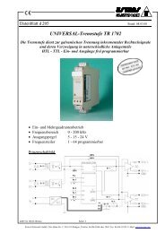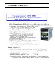
Druck PV 411 Pneumatic/Hydraulic Hand-pump User Manual
Druck PV 411 Pneumatic/Hydraulic Hand-pump User Manual
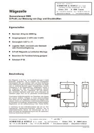
Druck PV 411 Pneumatic/Hydraulic Hand-pump User Manual

You also want an ePaper? Increase the reach of your titles
YUMPU automatically turns print PDFs into web optimized ePapers that Google loves.
<strong>Druck</strong> <strong>PV</strong> <strong>411</strong><br />
<strong>Pneumatic</strong>/<strong>Hydraulic</strong> <strong>Hand</strong>-<strong>pump</strong><br />
<strong>User</strong> <strong>Manual</strong><br />
© <strong>Druck</strong> Limited 2000<br />
This document is the property of <strong>Druck</strong> Limited and may not be copied or otherwise reproduced,<br />
communicated in any way to third parties, nor stored in any Data Processing System<br />
without the express written authorisation of <strong>Druck</strong> Limited.<br />
K258 Issue No. 1
<strong>Druck</strong> <strong>PV</strong> <strong>411</strong> <strong>User</strong> <strong>Manual</strong><br />
Introduction<br />
This technical manual provides operating instructions for the <strong>PV</strong> <strong>411</strong><br />
<strong>Pneumatic</strong>/hydraulic hand-<strong>pump</strong> compatible with the requirements<br />
of line operation.<br />
Safety<br />
The manufacturer has designed this equipment to be safe when<br />
operated using the procedures detailed in this manual. The user<br />
must not use this equipment for any other purpose than that stated.<br />
Only use hydraulic fluids stated in the specification.<br />
This manual contains safety and operating instructions which must<br />
be followed to make sure of safe operation and to keep the<br />
equipment in a safe condition. The safety instructions are either<br />
warnings or cautions issued to protect the user and the equipment<br />
from injury or damage. Use suitably qualified personnel and good<br />
engineering practice for all procedures in this manual.<br />
Pressure<br />
Do not apply pressure greater than the safe working pressure<br />
stated in the specification.<br />
Technical advice<br />
For technical advice contact the manufacturer or subsidiary.<br />
CE<br />
This product meets the essential requirements of the relevant<br />
EEC directives.<br />
Page i K258 Issue No. 1
<strong>Druck</strong> <strong>PV</strong> <strong>411</strong> <strong>User</strong> <strong>Manual</strong><br />
ABBREVIATIONS<br />
The following abbreviations are used in this publication.<br />
Note<br />
Abbreviations are the same in the singular and plural.<br />
°C degrees Celsius<br />
BSP British standard pipe thread<br />
cm centimetre<br />
°F degrees Fahrenheit<br />
inHg inches of mercury<br />
lbs pounds<br />
ISO International Standards Organisation<br />
kg kilogram<br />
m metre<br />
mbar millibar<br />
mm millimetre<br />
mmH 2 O millimetres of water<br />
NPT National pipe thread<br />
PRV pressure relief valve<br />
psi pounds per square inch<br />
PTFE polytetraflouroethylene<br />
SAE Society of Automotive Engineers<br />
UUT Unit under test<br />
Symbols<br />
The following symbols mark this equipment:<br />
Read the manual before use.<br />
Refer to the manual.<br />
K258 Issue No. 1 Page ii
<strong>Druck</strong> <strong>PV</strong> <strong>411</strong> <strong>User</strong> <strong>Manual</strong><br />
CONTENTS<br />
Title page<br />
Introduction ............................................................................................... 1<br />
<strong>Pneumatic</strong> <strong>pump</strong> .................................................................................... 1<br />
<strong>Hydraulic</strong> <strong>pump</strong> ...................................................................................... 1<br />
Specification ........................................................................................... 3<br />
Operation ............................................................................................... 4<br />
Pressure/vacuum configuration ............................................................. 4<br />
Connecting the <strong>pump</strong> ....................................................................... 5<br />
Selector valve ................................................................................... 5<br />
Scissor-action handles limit adjuster ................................................ 6<br />
<strong>Pneumatic</strong> Operation ........................................................................................ 7<br />
Volume adjuster ................................................................................ 7<br />
Generating pneumatic pressure and vacuum ................................... 8<br />
Pressure ............................................................................................ 8<br />
Vacuum ............................................................................................. 8<br />
<strong>Hydraulic</strong> Operation ........................................................................................ 10<br />
Fluid reservoir ....................................................................................... 10<br />
Fitting ......................................................................................... 12<br />
Filling ......................................................................................... 12<br />
Priming the system .............................................................................. 13<br />
Vacuum priming......................................................................... 13<br />
Pre-filling .................................................................................... 14<br />
Setting pressure relief valve ................................................................ 14<br />
Generating hydraulic pressure ............................................................. 15<br />
Multimedia ........................................................................................... 16<br />
Flushing ..................................................................................... 16<br />
Fault finding .......................................................................................... 17<br />
Approved service agents ..................................................................... 18<br />
Annex A<br />
Returned Goods Procedure ................................................................. 19<br />
ILLUSTRATIONS<br />
Figure title page<br />
1 General view ............................................................................... 2<br />
2 Fitting the reservoir ................................................................... 11<br />
Page iii K258 Issue No. 1
<strong>Druck</strong> <strong>PV</strong> <strong>411</strong> <strong>User</strong> <strong>Manual</strong><br />
Introduction<br />
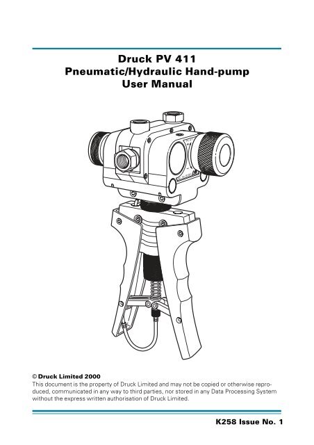
The <strong>PV</strong> <strong>411</strong> hand-<strong>pump</strong> generates either pneumatic pressure and<br />
vacuum or hydraulic pressure. The scissor-action handles provide<br />
pneumatic pressure and vacuum generation and, in the hydraulic<br />
mode, provides hydraulic pressure generation for system priming.<br />
<strong>Pneumatic</strong> <strong>pump</strong> (Figure 1)<br />
A selector valve vents the system, to atmosphere, between<br />
selections of pressure and vacuum. Operating the scissor-action<br />
handles provides the <strong>pump</strong>ing stroke, for pressure generation.<br />
A volume adjuster allows small adjustments of the system<br />
pressure.<br />
<strong>Hydraulic</strong> <strong>pump</strong> (Figure 1)<br />
The selector valve vents the system, to the reservoir, between<br />
selections of pressure and vacuum (used in the priming process).<br />
The volume adjuster generates the required system pressure. A<br />
fluid reservoir, screwed into the inlet port on the top of the hand<strong>pump</strong><br />
completes the hydraulic circuit. A pressure relief valve can<br />
be set to limit maximum pressure between 30 to 700 bar.<br />
Page 1 K258 Issue No. 1
<strong>Druck</strong> <strong>PV</strong> <strong>411</strong> <strong>User</strong> <strong>Manual</strong><br />
Figure 1, General view<br />
K258 Issue No. 1 Page 2
<strong>Druck</strong> <strong>PV</strong> <strong>411</strong> <strong>User</strong> <strong>Manual</strong><br />
Specification<br />
Pressure range<br />
<strong>Pneumatic</strong> .........................................................................0 to 60 bar<br />
Vacuum ..................................................................0 to -0.95 bar *<br />
<strong>Hydraulic</strong> ....................................................................... 0 to 700 bar<br />
Maximum safe working pressure ........................................... 700 bar<br />
<strong>Hydraulic</strong> fluid .................................................. Demineralised water<br />
or mineral-based oils<br />
<strong>Hydraulic</strong> fluids must be compatible with:<br />
Stainless steel, anodised aluminium, nitrile rubber,<br />
PTFE, polypropylene, delrin, acrylic and nylon.<br />
Pressure connections: .................................1/4” BSP parallel female<br />
Weight (approximate): .............................................................. 1.1 kg<br />
Dimensions<br />
Length ............................................................................ 260 mm<br />
Width ............................................................................ 135 mm<br />
Depth .............................................................................. 95 mm<br />
* This value assumes atmospheric pressure at 1 bar and will vary<br />
depending on atmospheric pressure.<br />
Page 3 K258 Issue No. 1
<strong>Druck</strong> <strong>PV</strong> <strong>411</strong> <strong>User</strong> <strong>Manual</strong><br />
Operation<br />
WARNINGS<br />
1 BEFORE APPLYING PRESSURE, MAKE SURE ALL CONNECTIONS<br />
ARE CORRECT AND EQUIPMENT IS INTERNALLY CLEAN AND<br />
FREE FROM DAMAGE.<br />
2 MAKE SURE THAT ALL EQUIPMENT IS TO THE CORRECT<br />
PRESSURE RATING.<br />
3 DO NOT EXCEED THE MAXIMUM OPERATING PRESSURE<br />
STATED IN THE SPECIFICATION.<br />
4 OBSERVE THE RELEVANT HEALTH AND SAFETY PRECAUTIONS.<br />
Note<br />
Wherever possible, use o-ring seals in the connection ports<br />
this is the recommended method of sealing.<br />
Pressure/vacuum Configuration (Figure 1)<br />
In pressure mode, air/fluid is drawn in through the inlet port on the<br />
top of the <strong>pump</strong> and forced out through the two outlet ports.<br />
In vacuum mode, the air/fluid flow is reversed as air/fluid is drawn<br />
in through the top and rear outlet ports and expelled through the<br />
inlet port.<br />
K258 Issue No. 1 Page 4
<strong>Druck</strong> <strong>PV</strong> <strong>411</strong> <strong>User</strong> <strong>Manual</strong><br />
Connecting the Pump<br />
Connections can be made to the <strong>pump</strong> either directly or using the<br />
range of adaptors supplied in the optional test kit.<br />
Direct<br />
The ports can be fitted with any suitable length 1/4 BSP male<br />
connector, sealing either with an o-ring at the bottom of the port or<br />
a bonded seal at the top. Fit a suitable blanking plug to an unused<br />
port.<br />
Swivel Adaptors<br />
The single, 1/4 BSP, swivel adaptor connects with a range of fixed<br />
adaptors. Using the knurled grip-feature, hand-tighten (clockwise)<br />
the swivel adaptor, until it is fully inserted.<br />
Swivel <strong>pump</strong> head<br />
The <strong>pump</strong> head swivels through 140° providing optimum viewing<br />
angle and bench-top operation. Placing the <strong>pump</strong> on the bench<br />
allows greater force to be applied to the scissor-action handles.<br />
Internal stops prevent further rotation of the <strong>pump</strong> head.<br />
Note<br />
Do not use excessive force when rotating the <strong>pump</strong> head.<br />
Selector Valve<br />
Pressure<br />
Turn the selector valve fully clockwise (in) position.<br />
Vacuum<br />
Turn the selector valve fully anti-clockwise (out) position.<br />
Page 5 K258 Issue No. 1
<strong>Druck</strong> <strong>PV</strong> <strong>411</strong> <strong>User</strong> <strong>Manual</strong><br />
Vent<br />
Slowly turn the selector valve to the centre position.<br />
CAUTION:<br />
AVOID DAMAGING THE INSTRUMENT UNDER TEST BY USING THE<br />
VOLUME ADJUSTER TO RELEASE HYDRAULIC PRESSURE.<br />
Scissor-action <strong>Hand</strong>les Limit Adjuster<br />
Turning the adjuster anti-clockwise reduces the stroke, turning the<br />
limit adjuster clockwise increases the stroke.<br />
For maximum pneumatic pressure generation, turn the limit<br />
adjuster fully clockwise.<br />
K258 Issue No. 1 Page 6
<strong>Pneumatic</strong> Operation<br />
<strong>Druck</strong> <strong>PV</strong> <strong>411</strong> <strong>User</strong> <strong>Manual</strong><br />
Volume Adjuster<br />
The volume adjuster can be used in different modes:<br />
Low pressure<br />
With the selector valve set to vent (open), turn the volume adjuster<br />
fully anti-clockwise (out).<br />
Turn the selector valve to the fully clockwise (in) position to select<br />
pressure.<br />
Turn the volume adjuster clockwise to generate pressure.<br />
High pressure<br />
Turn the volume adjuster to the mid-position. In this position fine<br />
adjustments of the generated pressure can be made. Using the<br />
scissor-action handles, generate the approximate pressure; then<br />
turn the volume adjuster clockwise (in) to increase the pressure or<br />
turn the volume adjuster anti-clockwise (out) to decrease the<br />
pressure.<br />
Vacuum<br />
Turn the selector valve fully anti-clockwise (out) position.<br />
Turn the volume adjuster to the mid-position. In this position fine<br />
adjustments of the generated vacuum can be made.<br />
Using the scissor-action handles, generate the approximate<br />
vacuum; then turn the volume adjuster clockwise (in) to decrease<br />
the vacuum or turn the volume adjuster anti-clockwise (out) to<br />
increase the vacuum.<br />
For low vacuum use the volume adjuster only.<br />
Page 7 K258 Issue No. 1
<strong>Druck</strong> <strong>PV</strong> <strong>411</strong> <strong>User</strong> <strong>Manual</strong><br />
Generating pneumatic pressure and vacuum<br />
Connect the <strong>pump</strong> as detailed on page 5.<br />
Notes<br />
Compressing a gas generates heat. Gas heated or cooled in<br />
an enclosed volume causes a pressure change. It is<br />
important to allow enough time for the heated gas to cool and<br />
the pressure to stabilize.<br />
The number of <strong>pump</strong>s required to generate a pressure<br />
depends on the volume of the system. Therefore, keep the<br />
system volume to a minimum.<br />
Pressure<br />
1 Turn the selector valve fully clockwise (in) position.<br />
2 Operate the scissor-action handles to generate the<br />
approximate pressure, allow time for thermal stabilization.<br />
3 If necessary, use the volume adjuster to adjust the required<br />
pressure.<br />
4 After attaining the required pressure operate the scissoraction<br />
handles to generate a higher pressure. Alternatively, vent<br />
the pressure to atmosphere by slowly turning (anti-clockwise) the<br />
selector valve to the centre position.<br />
Vacuum<br />
1 Turn the selector valve fully anti-clockwise (out) position.<br />
2 Operate the scissor-action handles to generate the<br />
approximate vacuum, allow time for thermal stabilization.<br />
3 If necessary, use the volume adjuster to adjust the required<br />
vacuum.<br />
K258 Issue No. 1 Page 8
<strong>Druck</strong> <strong>PV</strong> <strong>411</strong> <strong>User</strong> <strong>Manual</strong><br />
4 After attaining the required vacuum operate the scissor-action<br />
handles to generate a higher vacuum. Alternatively, vent<br />
atmosphere into the vacuum by slowly turning (anti-clockwise) the<br />
selector valve to the centre position.<br />
After completion, depressurize the <strong>pump</strong> and disconnect from the<br />
pipes and equipment.<br />
Page 9 K258 Issue No. 1
<strong>Druck</strong> <strong>PV</strong> <strong>411</strong> <strong>User</strong> <strong>Manual</strong><br />
<strong>Hydraulic</strong> Operation<br />
CAUTIONS<br />
/ DO NOT MIX HYDRAULIC FLUIDS.<br />
/ ONLY USE COMPATIBLE FLUIDS, REFER TO THE SPECIFICATION.<br />
/ ONLY FIT APPROPRIATE SEALS ON CONNECTIONS.<br />
/ OBSERVE ABSOLUTE CLEANLINESS WHEN USING THIS PUMP. DAMAGE<br />
CAN BE CAUSED IF EQUIPMENT CONNECTED TO THIS PUMP IS<br />
CONTAMINATED. AVOID PARTICULATE CONTAMINATION.<br />
Note<br />
Wherever possible, use o-ring seals in the connection ports,<br />
this is the recommended method of sealing.<br />
Fluid Reservoir (Figure 2)<br />
The main body of the reservoir is transparent acrylic providing a<br />
clear view of the contents.<br />
The reservoir can be removed from the <strong>pump</strong> without the need to<br />
empty the fluid, a self-sealing connection prevents leakage. The<br />
spring-loaded top cover seals under atmospheric pressure<br />
conditions, but vents excess internal pressure harmlessly in the<br />
event of inadvertent pressurization.<br />
The reservoir, connects to the inlet port on the top of the <strong>pump</strong> and<br />
supplies fluid to the <strong>pump</strong> system for pressure generation.<br />
In vacuum mode, used in priming, the fluid flow is reversed, fluid is<br />
drawn from the two outlet ports and through to the inlet port and<br />
the reservoir.<br />
K258 Issue No. 1 Page 10
<strong>Druck</strong> <strong>PV</strong> <strong>411</strong> <strong>User</strong> <strong>Manual</strong><br />
Figure 2, Fitting the Reservoir<br />
Page 11 K258 Issue No. 1
<strong>Druck</strong> <strong>PV</strong> <strong>411</strong> <strong>User</strong> <strong>Manual</strong><br />
Fitting<br />
Make sure that the correct o-ring seal is fitted to the inlet port to<br />
prevent leakage. Screw the reservoir (clockwise) into the inlet port.<br />
Note:<br />
Demineralised water is used to test the <strong>pump</strong> at<br />
manufacture. On shipment, there will be traces of<br />
demineralised water in the system.<br />
Filling<br />
Unscrew the reservoir cover lock nut and remove the reservoir<br />
cover.<br />
Using clean, recommended fluid fill the reservoir to approximately<br />
2/3 full.<br />
Refit the reservoir cover and re-tighten the reservoir cover lock nut.<br />
Connect the required pipes and equipment to the outlet ports.<br />
K258 Issue No. 1 Page 12
<strong>Druck</strong> <strong>PV</strong> <strong>411</strong> <strong>User</strong> <strong>Manual</strong><br />
Priming the system<br />
There are two methods: vacuum priming to extract the air or prefilling<br />
the system.<br />
Notes:<br />
1 If air remains in the system, full pressure cannot be<br />
achieved as the air in the fluid compresses. Air must be<br />
removed from the system fluid.<br />
2 Both priming methods require the <strong>pump</strong> to be held in<br />
the vertical position to keep the reservoir bleed hole in fluid.<br />
Do not allow air to enter the system through this bleed hole.<br />
Vacuum priming (Figure 2)<br />
Connect the equipment as detailed on page 5.<br />
Air can be removed using the vacuum facility on the <strong>pump</strong>.<br />
Note:<br />
This method should not be used with vacuum-sensitive<br />
equipment.<br />
Turn selector valve fully out, anti-clockwise (vacuum position).<br />
Pump until bubbles stop appearing in the reservoir, (this generates<br />
a vacuum in the system).<br />
Turn the selector valve fully in, (this action releases the vacuum and<br />
rapidly fills the system with fluid from the reservoir).<br />
The <strong>pump</strong> and connected system is ready for use.<br />
Page 13 K258 Issue No. 1
<strong>Druck</strong> <strong>PV</strong> <strong>411</strong> <strong>User</strong> <strong>Manual</strong><br />
Pre-filling<br />
Connect the equipment as detailed on page 5.<br />
Turn the selector valve fully clockwise (in) position.<br />
Loosen the reservoir cover lock nut to open the reservoir cover and<br />
let atmospheric pressure into the top of the reservoir.<br />
Open the bleed valve on the UUT.<br />
Carefully operate the scissor-action handles to fill the system. Stop<br />
<strong>pump</strong>ing when fluid comes out of the bleed valve.<br />
Close the bleed valve on the UUT.<br />
If necessary, top-up the reservoir to the 2/3 level with clean fluid.<br />
Secure the reservoir cover by tightening the reservoir cover lock nut.<br />
The <strong>pump</strong> and connected system is ready for use.<br />
Setting Pressure Relief Valve (Figure 1)<br />
The pressure relief valve (PRV) can be set at pressures from 30 to<br />
700 bar.<br />
If the system pressure exceeds the set pressure, the PRV opens<br />
and vents fluid through the inlet port to the reservoir. When the<br />
pressure decreases, the PRV closes.<br />
To set the PRV, loosen the PRV locking screw<br />
and turn the PRV to release at the required<br />
pressure.<br />
Hold the PRV and turn the collar fully<br />
anti-clockwise.<br />
Tighten the PRV locking screw.<br />
K258 Issue No. 1 Page 14
Generating <strong>Hydraulic</strong> Pressure<br />
<strong>Druck</strong> <strong>PV</strong> <strong>411</strong> <strong>User</strong> <strong>Manual</strong><br />
Note<br />
Pressurizing a fluid generates heat. A fluid heated or cooled<br />
in an enclosed volume causes a pressure change. Allow<br />
enough time thermally stabilize.<br />
Open the selector valve anti-clockwise 1 turn.<br />
Screw the volume adjuster fully out (anti-clockwise).<br />
Close the selector valve.<br />
Use the scissor-action handles to generate the initial pressure.<br />
Then turn the volume adjuster clockwise to generate the required<br />
pressure, allow time for thermal stabilization.<br />
To reduce the pressure, turn the volume adjuster out (anticlockwise)<br />
to the required pressure.<br />
After completion, turn the volume adjuster fully out (anti-clockwise)<br />
and turn the selector valve to depressurize the <strong>pump</strong>. Disconnect<br />
from the pipes and equipment.<br />
Page 15 K258 Issue No. 1
<strong>Druck</strong> <strong>PV</strong> <strong>411</strong> <strong>User</strong> <strong>Manual</strong><br />
Multimedia<br />
Changing from fluid to gas:<br />
Turn the volume adjuster fully clockwise (in).<br />
Use the vacuum selection, operate the scissor-action handles to<br />
draw fluid into the reservoir.<br />
Depressurize the <strong>pump</strong>.<br />
Unscrew and remove the reservoir.<br />
Invert the <strong>pump</strong> and, using the vacuum selection, operate the<br />
scissor-action handles to draw residual fluid out through the inlet<br />
port.<br />
WARNING:<br />
WHEN OUTLET PORTS ARE OPEN AND WITH THE SELECTOR<br />
VALVE SET TO PRESSURE, OPERATING THE SCISSOR-ACTION<br />
HANDLES RAPIDLY EXPELS FLUID.<br />
<strong>Pneumatic</strong> venting, after fluid use, can generate a fluid mist spray<br />
out of the inlet port.<br />
Flushing<br />
If necessary, use soapy water to remove any oil residue.<br />
K258 Issue No. 1 Page 16
Fault Finding<br />
If system pressure reduces, check the following:<br />
<strong>Druck</strong> <strong>PV</strong> <strong>411</strong> <strong>User</strong> <strong>Manual</strong><br />
1. Check the selector valve is in the correct position and properly<br />
tightened.<br />
2. Allow sufficient time after pressure generation for the<br />
temperature to stabilize.<br />
3. Check the adaptors, flexible pipe and connections between<br />
the <strong>pump</strong> and equipment under test for leaks. Tighten any loose<br />
joints and replace any seals that are worn or damaged.<br />
4. In hydraulic mode, if the volume adjuster can be wound fully<br />
in, but maximum pressure cannot be achieved, there is probably air<br />
trapped in the system. Re-prime, and repeat.<br />
If, for any reason, a fault occurs within the <strong>pump</strong>, it is<br />
recommended that the equipment be returned to an appointed<br />
agent.<br />
Page 17 K258 Issue No. 1
<strong>Druck</strong> <strong>PV</strong> <strong>411</strong> <strong>User</strong> <strong>Manual</strong><br />
Approved Service Agents<br />
The following are approved agents for the servicing of <strong>Druck</strong><br />
products.<br />
France<br />
<strong>Druck</strong> SA.,<br />
19 Rue Maurice Pellerin,<br />
92600 Asnières,<br />
France.<br />
Tel: (1) 43 34 24 75<br />
Fax: (1) 43 34 86 08<br />
Germany<br />
<strong>Druck</strong> Messtechnik GmbH,<br />
Auf dem Hohenstein 7,<br />
61231 Bad Nauheim,<br />
Germany.<br />
Tel: (6032) 93300<br />
Fax: (6032) 933080<br />
Holland<br />
<strong>Druck</strong> Nederland b.v.,<br />
Postbus 232,<br />
Zuideinde 37,<br />
2991 Lj Barendrecht,<br />
The Nederlands.<br />
Tel: (01806) 11555<br />
Fax: (01806) 18131<br />
Italy<br />
<strong>Druck</strong> Italia Srl.,<br />
Via Capecelatro 11,<br />
20148 Milano,<br />
Italy.<br />
Tel: (02) 48707166<br />
Fax: (02) 48705568<br />
K258 Issue No. 1 Page 18<br />
Japan<br />
<strong>Druck</strong> Japan KK,<br />
Medie Corp Building 8,<br />
2-4-14 Kichijyoji-Honcho,<br />
Musashino,<br />
Tokyo 180,<br />
Japan.<br />
Tel: (81) 422 20 7123<br />
Fax: (81) 422 20 7155<br />
UK<br />
<strong>Druck</strong> Limited,<br />
Fir tree Lane<br />
Groby,<br />
Leicester LE6 0FH<br />
England.<br />
Tel: (0116) 231 7100<br />
Fax: (0116) 231 7103<br />
USA<br />
<strong>Druck</strong> Incorporated,<br />
4 Dunham Drive,<br />
New Fairfield,<br />
Connecticut 06812,<br />
U.S.A.<br />
Tel: (203) 746 0400<br />
Fax: (203) 746 2494
<strong>Druck</strong> <strong>PV</strong> <strong>411</strong> <strong>User</strong> <strong>Manual</strong><br />
Annex A<br />
Returned goods procedure<br />
Should the unit become unserviceable and require repair it can be<br />
returned to the <strong>Druck</strong> Service Department.<br />
Please contact our Service Department, either by 'phone or fax, to<br />
obtain a Returned Goods Authorization (RGA) number, providing the<br />
following information:<br />
Product (i.e. <strong>PV</strong> <strong>411</strong>)<br />
Pressure medium (i.e. pneumatic, hydraulic )<br />
Serial number<br />
Details of defect/work to be undertaken<br />
Operating conditions<br />
Safety Precautions<br />
You must also tell us if the product has been in contact with<br />
anything hazardous or toxic and the relevant COSH references and<br />
precautions to be taken when handling.<br />
Important notice<br />
Service by unauthorized sources will affect the warranty and may<br />
not guarantee further performance.<br />
Page 19 K258 Issue No. 1