technical data
technical data
technical data

Create successful ePaper yourself
Turn your PDF publications into a flip-book with our unique Google optimized e-Paper software.
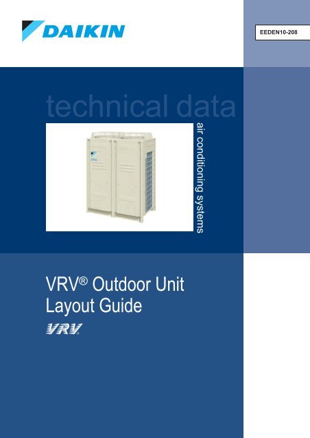
<strong>technical</strong> <strong>data</strong><br />
VRV ® Outdoor Unit<br />
Layout Guide<br />
air conditioning systems<br />
EEDEN10-208
<strong>technical</strong> <strong>data</strong><br />
VRV ® Outdoor Unit<br />
Layout Guide<br />
air conditioning systems<br />
EEDEN10-208
Contents<br />
P2<br />
P3<br />
P4<br />
P5<br />
P6<br />
P7<br />
P8<br />
P9<br />
P10<br />
P11<br />
P12<br />
P13<br />
P14<br />
P15<br />
P17<br />
P18<br />
What is an air short circuit?<br />
Situation01: Row installation<br />
Situation02: Collective installation (When Installation Space Allows)<br />
Situation03: Collective installation (When Installation Space is Limited)<br />
Situation04: The importance of louvres<br />
Situation05: Units surrounded by walls<br />
Situation05: In case of more severe conditions<br />
Guideline for the installation of VRV outdoor units, surrounded by walls<br />
Service Space<br />
Situation06: Floor-by-floor installation(Ducts required)<br />
Situation07: Floor-by-floor installation(Possibility of short circuit occurring)<br />
Situation07: Floor-by-floor installation(Possible improvement)<br />
Situation08: Installing units in two rows on intermediate floor<br />
Guideline for the installation of VRV outdoor units, floor by floor<br />
Appendix: Duct<br />
Memo<br />
1 Outdoor Unit Layout Guide
Introduction<br />
For air conditioning system designers, it is always difficult to find space to install<br />
outdoor units without sacrificing performance. Outdoor unit installation in severe<br />
conditions tends to cause discharged air short circuits, resulting in wasted energy and<br />
shortened machine life. In order for VRV outdoor unit systems to operate properly, it<br />
is necessary to ensure proper fresh air supply and proper exhaust of discharged air.<br />
This guide shows optimum layouts for outdoor units in various situations. We hope<br />
this brochure will be helpful to designers and engineers in their daily work.<br />
What is an air short circuit?<br />
Air short circuit<br />
It refers a phenomenon when discharged air (exhaust heat) from<br />
the outdoor unit is drawn back into the suction vent.<br />
If an air short circuit occurs<br />
1<br />
2<br />
3<br />
4<br />
���������������������<br />
Effi ciency of cooling operations will decrease.<br />
Shortage in capacity.<br />
High pressure cut-off will occur (operation stops).<br />
The lifespan of the outdoor unit will be shortened.<br />
����<br />
����<br />
����<br />
����<br />
����������������<br />
�����������<br />
����<br />
���<br />
�� �� �� �� ��<br />
����������������������������������������<br />
���<br />
����<br />
���<br />
����<br />
RXYQ10P(A) Series (10HP VRVIII outdoor unit)<br />
���<br />
���<br />
���<br />
����������������<br />
Outdoor Unit Layout Guide 2
S i t u a t i i o n 01<br />
����������������<br />
Align outdoor units so the suction side of the both front and back rows are facing<br />
outward in order to ensure a fresh air supply.<br />
Suction side should be<br />
facing outward<br />
���������������<br />
��������������������������������<br />
Fresh air<br />
Fresh air<br />
����������������������������������������������<br />
low Temperature high Temperature<br />
3 Outdoor Unit Layout Guide<br />
���������������<br />
��������������������������������������<br />
Original Layout<br />
Discharged air is drawn into<br />
the front row suction vents.<br />
Suction side should be<br />
facing outward<br />
TOP<br />
VIEW
S i t u a t i i o n 02<br />
������������������������(When Installation Space Allows)<br />
Installing units too close together will cause heat to build up in one area. To avoid<br />
this, install the units by dividing them into multiple groups.<br />
Make passages for the<br />
air to fl ow through<br />
Fresh air<br />
Fresh air<br />
��������������� ���������������<br />
�������������������������������� ������������������������������������<br />
Original Layout<br />
Fresh air is not supplied to<br />
the centre, and emanated<br />
heat is drawn back in.<br />
���������������������������������������������� TOP<br />
VIEW<br />
low Temperature high Temperature<br />
Outdoor Unit Layout Guide 4
S i t u a t i i o n 03<br />
������������������������(When Installation Space is Limited)<br />
Elevate the units and make sure that fresh air is supplied from underneath.<br />
Create an air passage<br />
underneath<br />
Fresh air<br />
���������������������������������������������� SIDE<br />
VIEW<br />
��������������� ���������������<br />
low Temperature high Temperature<br />
5 Outdoor Unit Layout Guide<br />
������������������<br />
��������������<br />
Original Layout<br />
Fresh air is not supplied to<br />
the centre, and emanated<br />
heat is drawn back in.<br />
���������������<br />
��������������<br />
�����������
S i t t u a t i i o n 04<br />
�������������������������<br />
A louvred wall improves fresh air supply.<br />
Fresh air<br />
Open louvre for fresh<br />
air to fl ow through<br />
���������������������������������������������� SIDE<br />
VIEW<br />
��������������� ���������������<br />
������������������<br />
������������ ����������������������<br />
�������������������<br />
low Temperature high Temperature<br />
Original Layout<br />
Discharged air cannot<br />
escape completely, and heat<br />
is drawn in again.<br />
Outdoor Unit Layout Guide 6
S i t t u a t i i o n 05<br />
�������������������������<br />
Elevate the units to make discharge vents and top of the wall at the same level.<br />
Fresh air<br />
���������������������������������������������� SIDE<br />
VIEW<br />
��������������� ���������������<br />
low Temperature high Temperature<br />
Original Layout<br />
Discharged air is trapped<br />
inside the walls and cannot<br />
escape properly, causing<br />
heat to be drawn in again.<br />
Note: Refer to guidelines (page 9) for space requirements.<br />
7 Outdoor Unit Layout Guide<br />
������������������<br />
���������<br />
Discharged air can<br />
escape from the top<br />
Fresh air<br />
����������������������<br />
�����������������������
����������������������������������<br />
��������������������������������������<br />
1.Technical background<br />
When installing VRV outdoor units collectively on the rooftop, the suction temperature increases due to the heat emanated from other outdoor units (air short circuit).<br />
As a result, in cooling system, the COP is lowered because of decreased equipment capacity and increased power consumption. In some cases, outdoor units stop<br />
operations due to abnormally high pressure. When installing these units, choose the most suitable layout for on-site space conditions from the installation options below,<br />
while taking walkway space and ventilation into consideration.<br />
* For other installation patterns, determine the appropriate installation method based on the space conditions, referring to the installation examples below.<br />
For the space in front of the units, please ensure there is enough space for refrigerant piping work. The required installation space shown in the illustrations is based on the<br />
cooling operation at 35°C of outside temperature. When the design outside temperature exceeds 35°C, make the inlet space larger than spaces shown in the illustrations.<br />
2. Installation examples (up to 24 units)<br />
Here shows basic collective installation examples of 16 HP units when 1600mm-high walls surround outdoor units, which is as high as outdoor units. Please be sure that<br />
the distances from each wall and between outdoor units are larger than the figures shown in illustration diagrams.<br />
���������������������������<br />
Determination of the Installation Location<br />
SELECTION OF LOCATION<br />
This unit, both indoor and outdoor, is suitable for installation in a commercial and light industrial environment.<br />
If installed as a household appliance it could cause electromagnetic interference.<br />
The VRV outdoor units should be installed in a location that meets the following requirements:<br />
1. The foundation is strong enough to support the weight of the unit and the floor is flat to prevent vibration and noise generation.<br />
2. The space around the unit is adequate for servicing and the minimum space for air inlet and air outlet is available.<br />
(Refer to below figure and choose one of both possibilities.)<br />
3. There is no danger of fire due to leakage of inflammable gas.<br />
4. Ensure that water cannot cause any damage to the location in case it drips out the unit (e.g. in case of a blocked drain pipe).<br />
5. The piping length between the outdoor unit and the indoor unit may not exceed the allowable piping length. (See “Example of connection”.)<br />
6. Select the location of the unit in such a way that neither the discharged air nor the sound generated by the unit disturb anyone.<br />
7. Make sure that the air inlet and outlet of the unit are not positioned towards the main wind direction.<br />
Frontal wind will disturb the operation of the unit. If necessary, use a windscreen to block the wind.<br />
����������<br />
�������������������������<br />
��������<br />
���<br />
�������<br />
���<br />
���� ���<br />
���<br />
������<br />
���������<br />
�������<br />
�������<br />
�������<br />
�������<br />
��<br />
��<br />
�����������������������������������<br />
���<br />
��� ���<br />
��<br />
�������<br />
�������<br />
�������������������<br />
����������������������������������� ����������������������������<br />
9 Outdoor Unit Layout Guide<br />
���<br />
���<br />
��� ����<br />
��<br />
�������<br />
�������<br />
��<br />
���� ����<br />
����<br />
�������<br />
�������<br />
Fresh air<br />
Fresh air
�������������<br />
���������������������������� ������������������������<br />
���������<br />
����������<br />
���������<br />
Notes<br />
�����������<br />
�������<br />
�����������<br />
�����������<br />
����������� ������������������������<br />
�������<br />
�����������<br />
����������<br />
���������� � �������<br />
�����������<br />
���������� �<br />
���������<br />
���������� ���������� �������<br />
�����������<br />
����������<br />
���������<br />
��������� ���������<br />
����������������������������<br />
���������<br />
����������<br />
�������<br />
�����������<br />
���������� �������<br />
�����������<br />
����������<br />
���������<br />
����������<br />
����������<br />
�����������<br />
�����������<br />
�������<br />
�����������<br />
�������<br />
�����������<br />
���������� ����������<br />
�����������<br />
�����������<br />
����������<br />
����������<br />
����������<br />
���������� ����������<br />
����������<br />
����������<br />
�����������<br />
�����������<br />
�����������<br />
�����������<br />
�����������<br />
1. Heights of walls in case of Patterns 1 and 2 :<br />
Front : 1500mm<br />
Suction side : 500mm<br />
Side : Height unrestricted.<br />
Installation space to be shown in this drawing is based on the cooling operation at 35 degrees outdoor air temperature. When the design outdoor air temperature<br />
exceeds 35 degrees or the load exceeds maximum ability because of much generation load of heat in all outdoor unit, take the suction side space more broadly<br />
than the space to be shown in this drawing.<br />
2. If the above wall heights are exceeded then h2/2 and h1/2 should be added to the front and suction side service spaces respectively as shown in<br />
the figure on the right.<br />
3. When installing the units most appropriate pattern should be selected from those shown above in order to obtain the best fit in the space available<br />
always bearing in mind the need to leave enough space for a person to pass between units and wall and for the air to circulate freely. (If more units are to be<br />
installed than are catered for in the above patterns your layout should take account of the possibility of short circuits.)<br />
4. The units should be installed to leave sufficient space at the front for the on site refrigerant piping work to be carried out comfortably.<br />
�������<br />
������������������������<br />
������� ���������� ����������<br />
����������� �������<br />
�����������<br />
�����������<br />
�������<br />
�����������<br />
�����������<br />
����������<br />
�����������<br />
�������<br />
����������� �����������<br />
����������<br />
�����������<br />
����������<br />
����������<br />
����������<br />
���������� ����������� �������<br />
�����������<br />
����������� ����������<br />
��<br />
������<br />
�������<br />
�����������<br />
��������������<br />
��<br />
�����<br />
Outdoor Unit Layout Guide 10<br />
���������
S i t t u a t i i o n 06<br />
���������������������������<br />
(Ducts required)<br />
Floor-by-floor installation is suitable for a VRV system if it is equipped with a duct.<br />
11 Outdoor Unit Layout Guide<br />
Why a<br />
duct is<br />
needed<br />
If ducts are not used:<br />
Discharged air cannot escape<br />
completely, and heat is drawn<br />
in again<br />
If ducts are used:<br />
Heat is allowed to escape<br />
through ducts to the outside<br />
Note: Refer to guidelines (page 16) for maximum capacity per floor<br />
and maximum number of consecutive floors.
S i t t u a t i i o n 07<br />
����������������������������<br />
(Possible improvement)<br />
Supply fresh air from the side, and orient the suction and discharge sides in different directions.<br />
Fresh<br />
air<br />
Note: Be aware of friction loss through the louvre on suction side.<br />
13 Outdoor Unit Layout Guide<br />
To prevent friction loss, we<br />
recommend not using louvres in<br />
front of discharge ducts.<br />
When an air passageway cannot be<br />
created on the side:<br />
Air is drawn in and released from the front.<br />
Original Layout<br />
When an air passage can be created on<br />
the side:<br />
Air is drawn in from the back and released<br />
from the front.<br />
Outdoor units on the upper fl oors draw<br />
in the exhaust heat from the lower<br />
fl oors. (Suction vents of outdoor units<br />
and discharge ducts are facing the<br />
same direction.)<br />
Close the front louvre (or use a solid<br />
wall) everywhere except in front of the<br />
discharge area to avoid recirculation of<br />
discharged air.<br />
Fresh air can be drawn<br />
in from the back.<br />
TOP<br />
VIEW
S i t t u a t i i o n 08<br />
��������������������������������������������������<br />
When installing two rows of units on one floor, it is necessary<br />
to arrange the air suction mechanism.<br />
Fresh<br />
air<br />
When there is no wall to the side<br />
The front row of units draw in air from the front, and the<br />
back row draw in air from the back.<br />
Fresh<br />
air<br />
Units in the back row should draw<br />
in air from the back. (Suction side<br />
should be facing the back.)<br />
When there is a wall to the side<br />
Elevate the front row of units, so that both rows can<br />
draw in air from the front.<br />
Fresh<br />
air<br />
Fresh<br />
air<br />
Suction side of both rows<br />
should be facing the front.<br />
Elevate the front<br />
row of units.<br />
Note: Do not merge ducts. Only one duct is to be installed on each fan in order to prevent air from being directly<br />
circulated into the neighbouring fan.<br />
Outdoor Unit Layout Guide 14
4. Design guidelines<br />
(1) Remove outdoor fan protective casing.<br />
(2) Install air discharge ducts on all outdoor units. Fix the duct against the louver if existing.<br />
(3) Louver angle: 20 degrees from horizontal<br />
(4) Air velocity: Discharge air VD=5–8 m/s and Suction air VS ≤1.6 m/s<br />
(5) Total pressure loss (through the discharge duct and the louver) should be less than 58.8 Pa for VRVII and 78.4Pa for VRVIII<br />
(with high static pressure setting).<br />
(6) Space should be left for suction air to circulate freely and for installation/service/maintenance to be done.<br />
5. Illustration<br />
Diagram below indicated the minimum distance for the unit layout<br />
in case of a floor-by-floor installation<br />
Air velocity<br />
VD: Air discharge effective velocity<br />
Flow rate<br />
VD=<br />
Discharge effective surface<br />
VS: Air suction effective velocity<br />
VS=<br />
Flow rate<br />
Suction effective surface<br />
Discharge effective surface = Actual discharge surface x Louver opening ratio Suction effective surface = Actual suction surface x<br />
Louver opening ratio<br />
5 m.s -1 ≤ VD ≤ 8 m.s -1<br />
��������<br />
����<br />
Louver angle: ≤ 20° downwards<br />
VS ≤ 1.6 m.s -1<br />
��������<br />
����<br />
��������<br />
����<br />
Total pressure loss: Less than 58.8 Pa for VRVII and 78.4Pa for VRVIII<br />
��������<br />
���� ��������<br />
����<br />
Example:<br />
40HP per floor installed, with a structure facing the installation at 5 meters distance.<br />
From graph, maximum number of floors the installation can be safely done: 20 Floors.<br />
�<br />
�<br />
��<br />
��<br />
��������<br />
����<br />
Outdoor Unit Layout Guide 16
�������������<br />
Discharge duct<br />
635mm width casing with 1 fan<br />
����<br />
����<br />
��<br />
���<br />
��<br />
���<br />
�<br />
���<br />
���<br />
��������<br />
���<br />
���<br />
���<br />
��������<br />
����<br />
�<br />
���<br />
���<br />
��������<br />
�����������<br />
���������<br />
��<br />
�� ��������<br />
�<br />
�������<br />
��<br />
��<br />
��� ���<br />
�����������<br />
���������<br />
�������� ��<br />
��<br />
�������<br />
��<br />
��<br />
��� ���<br />
�<br />
�<br />
�����<br />
�<br />
�<br />
�����<br />
Discharge duct<br />
930mm width casing with 1 fan<br />
����<br />
��<br />
���<br />
���<br />
���<br />
���������<br />
���<br />
�<br />
�����������<br />
���������<br />
�������� ��<br />
��<br />
�������<br />
��<br />
��<br />
��� ���<br />
Discharge duct<br />
Discharge duct<br />
1240mm width casing with 2 fans 1240mm width casing with 1 fan<br />
����<br />
��<br />
���<br />
���� ��<br />
����<br />
����������<br />
����������� ��<br />
Note 1: A gradual curve (large curve) in the discharge duct is effective in preventing friction loss.<br />
Note 2: Use only one duct per fan.<br />
17 Outdoor Unit Layout Guide<br />
����<br />
��<br />
��������<br />
��<br />
��� ���<br />
�<br />
�<br />
�����<br />
� �<br />
���������<br />
�������<br />
�<br />
�����
Memo<br />
Outdoor Unit Layout Guide 18
VRV ® Outdoor Unit<br />
Layout Guide<br />
Daikin’s unique position as a manufacturer of air<br />
conditioning equipment, compressors and<br />
refrigerants has led to its close involvement in<br />
environmental issues. For several years Daikin has<br />
had the intension to become a leader in the provision<br />
of products that have limited impact on the<br />
environment. This challenge demands the eco design<br />
and development of a wide range of products and an<br />
energy management system, resulting in energy<br />
conservation and a reduction of waste.<br />
Naamloze Vennootschap<br />
Zandvoordestraat 300<br />
B-8400 Oostende, Belgium<br />
www.daikin.eu<br />
BE 0412 120 336<br />
RPR Oostende<br />
Daikin Europe N.V. is approved by LRQA for its Quality<br />
Management System in accordance with the ISO9001<br />
standard. ISO9001 pertains to quality assurance regarding<br />
design, development, manufacturing as well as to services<br />
related to the product.<br />
ISO14001 assures an effective environmental<br />
management system in order to help protect human health<br />
and the environment from the potential impact of our<br />
activities, products and services and to assist in<br />
maintaining and improving the quality of the environment.<br />
Daikin units comply with the European regulations that<br />
guarantee the safety of the product.<br />
VRV ® products are not within the scope of the Eurovent<br />
certification programme.<br />
The present publication is drawn up by way of information only and does not<br />
constitute an offer binding upon Daikin Europe N.V.. Daikin Europe N.V. has<br />
compiled the content of this publication to the best of its knowledge. No<br />
express or implied warranty is given for the completeness, accuracy,<br />
reliability or fitness for particular purpose of its content and the products and<br />
services presented therein. Specifications are subject to change without<br />
prior notice. Daikin Europe N.V. explicitly rejects any liability for any direct or<br />
indirect damage, in the broadest sense, arising from or related to the use<br />
and/or interpretation of this publication. All content is copyrighted by Daikin<br />
Europe N.V..<br />
���������������<br />
EEDEN10-208 • 01/2010 • Copyright Daikin<br />
The present publication supersedes EEDEN09-208<br />
Prepared in Belgium by Lannoo (www.lannooprint.be), a company whose concern for<br />
the environmont is set in the EMAS and ISO 14001 systems.<br />
Responsible Editor: Daikin Europe N.V., Zandvoordestraat 300, B- 8400 Oostende