Balance Quality Requirements of Rigid Rotors - IRD Balancing
Balance Quality Requirements of Rigid Rotors - IRD Balancing
Balance Quality Requirements of Rigid Rotors - IRD Balancing

You also want an ePaper? Increase the reach of your titles
YUMPU automatically turns print PDFs into web optimized ePapers that Google loves.
<strong>IRD</strong> <strong>Balancing</strong> Technical Paper 1<br />
World’s Leading Supplier <strong>of</strong> S<strong>of</strong>t Bearing<br />
<strong>Balancing</strong> Machines & Instruments<br />
<strong>Balance</strong> <strong>Quality</strong> <strong>Requirements</strong><br />
<strong>of</strong> <strong>Rigid</strong> <strong>Rotors</strong><br />
The Practical Application <strong>of</strong> ISO 1940/1
<strong>Balance</strong> <strong>Quality</strong> <strong>Requirements</strong> <strong>of</strong> <strong>Rigid</strong> <strong>Rotors</strong><br />
The Practical Application <strong>of</strong> ISO 1940/1<br />
ABSTRACT<br />
International Standard ISO 1940/1 is a widelyaccepted<br />
reference for selecting rigid rotor<br />
balance quality. This paper is presented as a<br />
tutorial and user's reference <strong>of</strong> the standard and<br />
its practical applications.<br />
A simplified method is shown for determining<br />
permissible residual unbalance for various rotor<br />
classifications. Emphasis is given to allocating<br />
permissible residual unbalance to appropriate<br />
correction planes for rotor configurations, such<br />
as unsymmetrical, narrow and overhung rotors.<br />
Finally, a comparison <strong>of</strong> various balance quality<br />
grades is made with MIL-STD-167-1 and API<br />
balance limits.<br />
INTRODUCTION<br />
The International Standards Organization, ISO,<br />
published Standard 1940/1 "<strong>Balance</strong> <strong>Quality</strong><br />
<strong>Requirements</strong> <strong>of</strong> <strong>Rigid</strong> <strong>Rotors</strong>," which has been<br />
adopted by the American National Standards<br />
Institute, ANSI, as S2.19-1975, "<strong>Balance</strong> <strong>Quality</strong><br />
<strong>Requirements</strong> <strong>of</strong> Rotating <strong>Rigid</strong> Bodies." It has<br />
also been adopted by BRITISH Standards as BS<br />
6861: Part 1 and by GERMAN Standards as VDI<br />
2060.<br />
ISO 1940/1 requires an understanding <strong>of</strong><br />
balancing and its terminology if the standard is<br />
to be understood and used properly. The<br />
reader is directed to the paper's "<strong>Balance</strong><br />
Terminology" section for a summary <strong>of</strong> terms<br />
used in this paper.<br />
1<br />
USING THE STANDARD<br />
The use <strong>of</strong> the standard involves the following<br />
steps:<br />
1. Select a balance quality grade "G number"<br />
from Table 1 based on rotor type.<br />
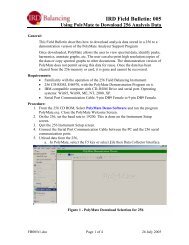
2. Use the Figure 1 (A or B) graph to determine<br />
the permissible residual specific unbalance<br />
value, e per for the rotor's maximum operating<br />
speed and the selected "G number." Then<br />
multiply e per by rotor weight to obtain the<br />
permissible residual unbalance, U per.<br />
3. Allocate U per to the balancing correction<br />
planes based on rotor configuration.<br />
Performing step 1 simply requires the user to<br />
find the rotor type that most nearly describes<br />
the one to be balanced.<br />
Step 2 is more involved as it requires using the<br />
graph in Figure 1 to find the permissible specific<br />
unbalance, followed by multiplying by rotor<br />
weight and then a constant to convert U per to<br />
proper units (gram-millimeters or ounce-inches).<br />
This step can be simplified by using some<br />
simple equations to calculate U per directly.<br />
Step 3, allocating U per, is <strong>of</strong>ten not performed<br />
because it is not easily understood.<br />
Therefore, the following pages provide a<br />
simplified method for step 2 and describe the<br />
procedures for step 3.
<strong>Balance</strong><br />
<strong>Quality</strong><br />
Grade<br />
G 4 000<br />
G 1 600<br />
G 630<br />
G 250<br />
G 100<br />
G 40<br />
G 16<br />
G 6.3<br />
G 2.5<br />
G 1<br />
G 0.4<br />
Table 1 <strong>Balance</strong> quality grades for various groups <strong>of</strong> representative rigid rotors<br />
(From ISO 1940/1)<br />
Product <strong>of</strong> the<br />
Relationship<br />
(1) (2)<br />
(eper x �)<br />
mm/s<br />
4 000<br />
1 600<br />
630<br />
250<br />
100<br />
40<br />
16<br />
6.3<br />
2.5<br />
1<br />
0.4<br />
2<br />
Rotor Types - General Examples<br />
Crankshaft/drives (3) <strong>of</strong> rigidly mounted slow marine diesel engines with uneven number <strong>of</strong> cylinders (4)<br />
Crankshaft/drives <strong>of</strong> rigidly mounted large two-cycle engines<br />
Crankshaft/drives <strong>of</strong> rigidly mounted large four-cycle engines<br />
Crankshaft/drives <strong>of</strong> elastically mounted marine diesel engines<br />
Crankshaft/drives <strong>of</strong> rigidly mounted fast four-cylinder diesel engines (4)<br />
Crankshaft/drives <strong>of</strong> fast diesel engines with six or more cylinders (4)<br />
Complete engines (gasoline or diesel) for cars, trucks and locomotives (5)<br />
Car wheels, wheel rims, wheel sets, drive shafts<br />
Crankshaft/drives <strong>of</strong> elastically mounted fast four-cycle engines with six or more cylinders (4)<br />
Crankshaft/drives <strong>of</strong> engines <strong>of</strong> cars, trucks and locomotives<br />
Drive shafts (propeller shafts, cardan shafts) with special requirements<br />
Parts <strong>of</strong> crushing machines<br />
Parts <strong>of</strong> agricultural machinery<br />
Individual components <strong>of</strong> engines (gasoline or diesel) for cars, trucks and locomotives<br />
Crankshaft/drives <strong>of</strong> engines with six or more cylinders under special requirements<br />
Parts <strong>of</strong> process plant machines<br />
Marine main turbine gears (merchant service)<br />
Centrifuge drums<br />
Paper machinery rolls; print rolls<br />
Fans<br />
Assembled aircraft gas turbine rotors<br />
Flywheels<br />
Pump impellers<br />
Machine-tool and general machinery parts<br />
Medium and large electric armatures (<strong>of</strong> electric motors having at least 80 mm shaft height) without<br />
special requirements<br />
Small electric armatures, <strong>of</strong>ten mass produced, in vibration insensitive applications and/or with<br />
vibration-isolating mountings<br />
Individual components <strong>of</strong> engines under special requirements<br />
Gas and steam turbines, including marine main turbines (merchant service)<br />
<strong>Rigid</strong> turbo-generator rotors<br />
Computer memory drums and discs<br />
Turbo-compressors<br />
Machine-tool drives<br />
Medium and large electric armatures with special requirements<br />
Small electric armatures not qualifying for one or both <strong>of</strong> the conditions specified for small electric<br />
armatures <strong>of</strong> balance quality grade G 6.3<br />
Turbine-driven pumps<br />
Tape recorder and phonograph (gramophone) drives<br />
Grinding-machine drives<br />
Small electric armatures with special requirements<br />
Spindles, discs and armatures <strong>of</strong> precision grinders<br />
Gyroscopes<br />
1) � = 2πn/60 ≈ n/10, if n is measured in revolutions per minute and � in radians per second.<br />
2) For allocating the permissible residual unbalance to correction planes, refer to "AIIocation <strong>of</strong> U per to correction planes."<br />
3) A crankshaft/drive is an assembly which includes a crankshaft, flywheel, clutch, pulley, vibration damper, rotating portion <strong>of</strong> connecting rod, etc.<br />
4) For the purposes <strong>of</strong> this part <strong>of</strong> ISO 1940/1, slow diesel engines are those with a piston velocity <strong>of</strong> less than 9 m/s; fast diesel engines are those<br />
with a piston velocity <strong>of</strong> greater than 9 m/s.<br />
5) In complete engines, the rotor mass comprises the sum <strong>of</strong> all masses belonging to the crankshaft/drive described in note 3 above.
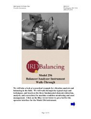
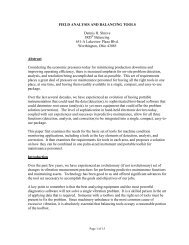
PERMISSIBLE RESIDUAL UNBALANCE eper in lb-in/lb <strong>of</strong> rotor weight<br />
or<br />
CENTER OF GRAVITY DISPLACEMENT, eper in inches<br />
Figure 1-A Maximum permissible residual unbalance, e per<br />
(Imperial values adapted from ISO 1940/1)<br />
MAXIMUM SERVICE SPEED IN RPM<br />
3
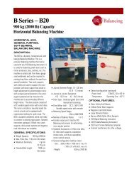
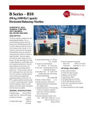
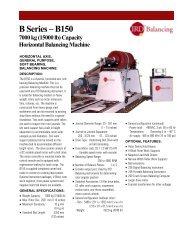
PERMISSIBLE RESIDUAL UNBALANCE, eper in g-mm/kg <strong>of</strong> rotor weight<br />
OR<br />
CENTER OF GRAVITY DISPLACEMENT, eper in µm<br />
Figure 1-B Maximum permissible residual unbalance, e per<br />
(From ISO 1940/1)<br />
MAXIMUM SERVICE SPEED IN RPM<br />
4
BALANCE QUALITY GRADES<br />
Table 1 shows the balance quality grades for a<br />
variety <strong>of</strong> rotor types. The "G" number is the<br />
product <strong>of</strong> specific unbalance and the angular<br />
velocity <strong>of</strong> the rotor at maximum operating speed<br />
and is a constant for rotors <strong>of</strong> the same type.<br />
G = e x � = constant<br />
This is based on the fact that geometrically similar<br />
rotors running at the same speed will have similar<br />
stresses in the rotor and its bearings.<br />
<strong>Balance</strong> quality grades are separated by a factor<br />
<strong>of</strong> 2.5. However, G numbers <strong>of</strong> intermediate value<br />
may be used to satisfy special requirements. For<br />
example, a standard pump impeller has a<br />
suggested balance quality grade <strong>of</strong> G 6.3. Special<br />
conditions may require a better balance quality <strong>of</strong><br />
G 4.0 to satisfy installation in an area with low<br />
structure-borne noise limits.<br />
DETERMINING PERMISSIBLE<br />
RESIDUAL UNBALANCE - U per<br />
Uper = eper x m<br />
(m = rotor mass)<br />
Permissible residual unbalance is a function <strong>of</strong> G<br />
number, rotor weight and maximum service speed<br />
<strong>of</strong> rotation. Instead <strong>of</strong> using the graph to look up<br />
the "specific unbalance" value for a given G<br />
number and service RPM and then multiplying by<br />
rotor weight (taking care to use proper units), U per<br />
can be calculated by using one <strong>of</strong> the following<br />
formulae:<br />
U per (oz-in) = 6.015 x G x W/N (W in Ib)<br />
U per (g-in) = 170.5 x G x W/N (W in Ib)<br />
U per (g-mm) = 9549 x G x W/N (W in kg)<br />
G = <strong>Balance</strong> quality grade from Table 1<br />
W = Rotor weight<br />
N = Maximum service RPM<br />
A slide rule that calculates U per is also available<br />
from some balancing machine manufacturers.<br />
5<br />
ALLOCATION OF U per<br />
TO CORRECTION PLANES<br />
U per is the total permissible residual unbalance<br />
and must be allocated to the balancing correction<br />
planes used based on rotor dimensions and<br />
configuration.<br />
For rotors balanced in a single correction plane,<br />
all <strong>of</strong> the U per applies to that correction plane.<br />
For rotors balanced in two correction planes, U per<br />
must be allocated to each correction plane based<br />
on rotor configuration and dimensions.<br />
Figure 2 Symmetrical rotors<br />
SYMMETRICAL ROTORS<br />
Rules for symmetrical rotors. (See Figure 2.)<br />
1. Correction planes are between bearings.<br />
2. Distance "b" is greater than 1/3 "d."<br />
3. Correction planes are equidistant from the<br />
center <strong>of</strong> gravity.<br />
U per left = U per right = U per/2<br />
When correction planes are NOT equidistant from<br />
the center <strong>of</strong> gravity, then -<br />
U per left = U per (h R/b)<br />
U per right = U per (h L/b)<br />
The U per left or U per right should not be less than<br />
30% or more than 70% U per. If they are, then<br />
use rules for narrow rotors.
ROTORS WITH OUTBOARD<br />
CORRECTION PLANES<br />
Figure 3 Rotor with outboard planes<br />
Rules for rotors with correction planes outside the<br />
bearings. This is <strong>of</strong>ten referred to as a "dumbbell"<br />
rotor configuration. (See Figure 3)<br />
Both correction planes are outboard <strong>of</strong> the<br />
bearings.<br />
b > d<br />
Adjust U per by ratio <strong>of</strong> d/b. (Reduces U per)<br />
U per = U per (d/b) U per = Adjusted value<br />
When correction planes are not equidistant from<br />
the center <strong>of</strong> gravity, calculate U per left and right<br />
as follows:<br />
U per left = U per (h R/b) U per right = U per (h L/b)<br />
OVERHUNG AND NARROW ROTORS<br />
Figure 4 Overhung rotors<br />
Rules for overhung and narrow rotors.<br />
(See Figures 4 and 5).<br />
1. Distance between correction planes is less than<br />
1/3 the distance between bearings. b < 0.33 d.<br />
2. Assumes equal permissible dynamic bearing<br />
loads.<br />
6<br />
3. Couple corrections are made 180° apart in their<br />
respective planes.<br />
4. The plane for static corrections may be a third<br />
plane or either <strong>of</strong> the planes used for couple<br />
corrections.<br />
5. Allocate U per as static and couple residual<br />
unbalance as follows:<br />
U per static = U per/2 x d/2c<br />
U per couple = U per/2 x 3d/4b<br />
Figure 5 Narrow rotors<br />
Permissible unbalance allocations for overhung<br />
and narrow rotors require that two plane<br />
unbalance corrections be divided into static and<br />
couple unbalance equivalents. This can be done<br />
graphically by plotting the two plane balance<br />
solution vectors U L and U R as shown in Figure 6.<br />
Connect vectors U L and U R as shown. The vector<br />
from the origin to the mid-point <strong>of</strong> vector C L-C R is<br />
one-half the rotor's static unbalance. Vectors C L<br />
and C R are the couple unbalance.<br />
Figure 6 Static-couple graphical derivation
1 in = 25.4 mm<br />
1 mm = .0394 in<br />
1 lb = 454 g<br />
1 kg = 2.2 lb<br />
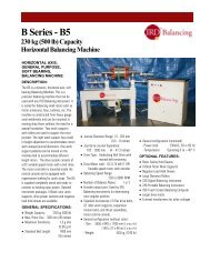
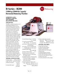
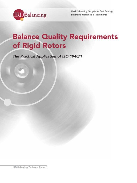
Figure 7 Comparision <strong>of</strong> API, ISO & MIL-STD-167-1 balance tolerances<br />
MAXIMUM CONTINUOUS OPERATING RPM<br />
Useful Conversions<br />
1 mil = 25.4 µm<br />
1 µm = .0394 mil<br />
1 oz = 28.35 g<br />
1 g = .0353 oz<br />
COMPARING API, ISO & MIL-STD-167-1<br />
BALANCE TOLERANCES<br />
U per = Permissible residual unbalance FOR EACH CORRECTION PLANE in ounce inches. (oz-in)<br />
W = Rotor Weight In Pounds. W = 1000 lbs. for all examples shown.<br />
N = Maximum Continuous Operating RPM.<br />
G = ISO <strong>Balance</strong> <strong>Quality</strong> Grade Number, i.e. 6.3, 2.5, 1.0 etc.<br />
F c < 10% Journal Static Load Uper = 56.347 x (Journal Static Load W/2)<br />
ISO Uper = G x 6.015 x W/2<br />
N<br />
MIL-STD-167-1 Uper = 0.177 W (0 to 150 RPM)<br />
= 4000 W / N2 (150 to 1000 RPM)<br />
= 4 W / N (Above 1000 RPM)<br />
W = Total Rotor Weight<br />
API Uper = 4 W / N (W = Journal static Load)<br />
F c = 1.77 (RPM/1000) 2 (oz-in) [Centrifugal Force]<br />
DATA TABULATION<br />
MIL-STD-167 ISO G 6.3 ISO G 2.5 ISO G 1.0 API FC = 10%W/2<br />
N<br />
150<br />
500<br />
1000<br />
2000<br />
3000<br />
4000<br />
5000<br />
6000<br />
7000<br />
Uper oz-in Centr.<br />
Force<br />
177<br />
16 42<br />
1.33<br />
1.0<br />
.8<br />
.67<br />
.57<br />
7<br />
7<br />
7<br />
7<br />
14<br />
21<br />
28<br />
35<br />
43<br />
49<br />
Uper oz-in Centr.<br />
Force<br />
126.0<br />
38.0<br />
19.0<br />
9.5<br />
6.3<br />
4.7<br />
3.8<br />
3.2<br />
2.7<br />
5<br />
17<br />
34<br />
67<br />
100<br />
133<br />
168<br />
201<br />
234<br />
Uper oz-in Centr.<br />
Force<br />
50.0<br />
15.0<br />
7.5<br />
3.8<br />
2.5<br />
1.9<br />
1.5<br />
1.3<br />
1.1<br />
2.0<br />
6.6<br />
13.3<br />
26.6<br />
39.8<br />
53.8<br />
66.4<br />
79.7<br />
92.8<br />
Uper oz-in Centr.<br />
Force<br />
20.0<br />
6.0<br />
3.0<br />
1.5<br />
1.0<br />
.8<br />
.6<br />
.5<br />
.4<br />
0.8<br />
2.7<br />
5.3<br />
10.6<br />
15.9<br />
21.2<br />
26.6<br />
31.9<br />
37.3<br />
N 2<br />
Uper oz-in Centr.<br />
Force<br />
13.3<br />
4.0<br />
2.0<br />
1.0<br />
0.6<br />
0.5<br />
0.4<br />
0.3<br />
0.3<br />
0.5<br />
1.8<br />
3.5<br />
7.1<br />
9.6<br />
14.2<br />
17.7<br />
19.1<br />
26.0<br />
1252.0<br />
113.0<br />
28.0<br />
7.0<br />
3.1<br />
1.8<br />
1.1<br />
0.8<br />
0.6<br />
1 oz in = 720 g mm<br />
1 g mm = .00139 oz in<br />
Uper oz-in Centr.<br />
Force<br />
50<br />
50<br />
50<br />
50<br />
50<br />
50<br />
50<br />
50<br />
50<br />
Copyright 1999 <strong>IRD</strong> <strong>Balancing</strong>
STANDARDS COMPARISON<br />
A frequent question is, "How do the ISO 1940/1<br />
quality grades compare with other balancing<br />
standards, such as API and MIL-STD-167-1?"<br />
A comparison graph and data tabulation appears<br />
in Figure 7. Three ISO grades (6.3, 2.5 and 1.0),<br />
MIL-STD-167-1 and API balance quality standards<br />
are compared in tabular and graphical form.<br />
In addition, U per was calculated for a constant<br />
centrifugal force <strong>of</strong> 50 pounds (10% <strong>of</strong> static<br />
journal load). A symmetrical 1000 pound rotor<br />
with the C.G. midway between bearings and<br />
correction planes was used. Static load at each<br />
journal is 500 pounds and centrifugal force was<br />
calculated for each U per.<br />
To more clearly show the relationship, a<br />
summary <strong>of</strong> balance quality standards and their<br />
corresponding centrifugal forces are shown in<br />
Table 2 as a percentage <strong>of</strong> journal static loading<br />
for 900, 1200, 1800 and 3600 RPM.<br />
<strong>Balance</strong><br />
<strong>Quality</strong><br />
Std.<br />
ISO G6.3<br />
ISO G2.5<br />
MIL-STD<br />
ISO G1.0<br />
API<br />
Table 2 Centrifugal force as a percent<br />
<strong>of</strong> journal static load<br />
900 RPM 1200 RPM 1800 RPM 3600 RPM<br />
U per<br />
oz-in<br />
21<br />
8.3<br />
4.4<br />
3.3<br />
2.2<br />
Uper Uper Uper F/L % F/L % F/L % F/L %<br />
oz-in oz-in oz-in<br />
6.0%<br />
2.4%<br />
1.3%<br />
0.9%<br />
0.6%<br />
15.8<br />
6.3<br />
3.3<br />
2.5<br />
1.7<br />
8.1%<br />
3.2%<br />
1.7%<br />
1.3%<br />
0.8%<br />
10.5<br />
Uper = Permissible residual unbalance for each correction plane<br />
F = Centrifugal force due to residual unbalance<br />
L = Journal static load L = W/2 W = 1000 lbs.<br />
From the graph and Table 2, it is easy to see<br />
that the API standard demands a low residual<br />
unbalance level and with a smaller unbalance<br />
force load on the rotor's bearings. However,<br />
the effort to achieve this result may not always<br />
be cost effective.<br />
Published balance tolerances provide everyone<br />
with a common reference for communicating<br />
balance quality expectations, as well as what<br />
the provider promises. Proper interpretation<br />
and application <strong>of</strong> each is needed to realize<br />
satisfaction for everyone.<br />
4.2<br />
2.2<br />
1.7<br />
1.1<br />
12.0%<br />
4.8%<br />
2.5%<br />
1.90%<br />
1.3%<br />
5.3<br />
2.1<br />
1.1<br />
0.8<br />
0.6<br />
24.1%<br />
9.6%<br />
5.1%<br />
3.7%<br />
2.6%<br />
8<br />
BALANCE TERMINOLOGY<br />
BALANCE QUALITY GRADE - GXXX - for rigid<br />
rotors, G, is the product <strong>of</strong> specific unbalance, e,<br />
and rotor maximum service angular velocity.<br />
Service angular velocity is service RPM expressed<br />
in radians per second.<br />
G = e x � = constant<br />
CENTER OF GRAVITY - the point in a body through<br />
which the resultant <strong>of</strong> the weights <strong>of</strong> its<br />
component particles passes for all orientations <strong>of</strong><br />
the body with respect to a gravitational field C.G.<br />
CORRECTION (BALANCING) PLANE - plane<br />
perpendicular to the shaft axis <strong>of</strong> a rotor in which<br />
correction for unbalance is made.<br />
COUPLE UNBALANCE - that condition <strong>of</strong><br />
unbalance for which the central principal axis<br />
intersects the shaft axis at the center <strong>of</strong> gravity.<br />
CRITICAL SPEED - speed at which a system<br />
resonance is excited. The resonance may be <strong>of</strong><br />
the journal supports (rigid mode) or flexure <strong>of</strong> the<br />
rotor (flexural mode).<br />
DYNAMIC UNBALANCE - that condition <strong>of</strong><br />
unbalance for which the central principal axis is not<br />
parallel to and does not intersect the shaft axis.
Note: Dynamic unbalance is equivalent to two<br />
unbalance vectors in two specified planes which<br />
completely represent the total unbalance <strong>of</strong> the<br />
rotor.<br />
Note: Dynamic unbalance may also be resolved<br />
into static and couple unbalance vectors whose<br />
vector sum is also equal to the total unbalance <strong>of</strong><br />
the rotor.<br />
FLEXIBLE ROTOR - a rotor that does not satisfy the<br />
rigid rotor definition because <strong>of</strong> elastic deflection.<br />
PERMISSIBLE RESIDUAL UNBALANCE U per - the<br />
maximum residual unbalance permitted for a<br />
rotor or in a correction plane.<br />
U per = e per x m<br />
where m = rotor mass<br />
PRINCIPAL INERTIA AXIS - the coordinate<br />
directions corresponding to the principal moments<br />
<strong>of</strong> inertia. In balancing, the term principal inertia<br />
axis is used to designate the central principal axis<br />
most nearly coincident with the shaft axis <strong>of</strong> the<br />
rotor.<br />
RESIDUAL (FINAL) UNBALANCE - the unbalance<br />
<strong>of</strong> any kind that remains after balancing.<br />
RIGID ROTOR - a rotor is considered rigid if its<br />
unbalance can be corrected in any two correction<br />
planes. After the correction, the residual<br />
unbalance does not change significantly at any<br />
speed up to the maximum service speed.<br />
ROTOR - a body capable <strong>of</strong> rotation which<br />
generally has journals supported by bearings.<br />
9<br />
STATIC UNBALANCE - that condition <strong>of</strong> unbalance<br />
for which the central principal axis is displaced<br />
only parallel to the shaft axis.<br />
SPECIFIC UNBALANCE - static unbalance U<br />
divided by rotor mass m (i.e., mass eccentricity).<br />
Note: In the case <strong>of</strong> a rotor with two correction<br />
planes, specific unbalance may refer to the<br />
unbalance in one plane divided by rotor mass<br />
allocated to that plane.<br />
REFERENCES<br />
1. ISO 1940/1, "<strong>Balance</strong> <strong>Quality</strong> <strong>Requirements</strong> <strong>of</strong><br />
<strong>Rigid</strong> <strong>Rotors</strong>." International Organization for<br />
Standardization.<br />
2. ANSI S2. 19-1975, "<strong>Balance</strong> <strong>Quality</strong><br />
<strong>Requirements</strong> <strong>of</strong> Rotating <strong>Rigid</strong> Bodies."<br />
American National Standards Institute.<br />
3. BS 6861: Part 1, "<strong>Balance</strong> <strong>Quality</strong> <strong>Requirements</strong><br />
<strong>of</strong> <strong>Rigid</strong> <strong>Rotors</strong>." British Standards Institution.<br />
4. VDI 2060, "<strong>Balance</strong> <strong>Quality</strong> <strong>Requirements</strong> <strong>of</strong><br />
<strong>Rigid</strong> <strong>Rotors</strong>." German Standards Institution.<br />
5. Standard Paragraphs, API Subcommittee on<br />
Mechanical Equipment, Revision 19, September<br />
1991. American Petroleum Institute.<br />
6. MIL-STD-167-1 (SHIPS), 1 May 1974,<br />
"Mechanical Vibrations <strong>of</strong> Shipboard<br />
Equipment." Department <strong>of</strong> the Navy,<br />
Naval Ship Systems Command.<br />
7. "DYNAMIC BALANCING HANDBOOK,"<br />
October 1990, <strong>IRD</strong> Mechanalysis Inc.<br />
8. ISO 1925, “<strong>Balancing</strong> Vocabulary.”<br />
International Organization for Standardization.
USA Headquarters<br />
USA: Louisville,KY<br />
1.888.473.2251 phone<br />
1.502.238.1001 fax<br />
www.irdbalancing.com<br />
sales@irdbalancing.com<br />
UK: Chester<br />
44.1244.538170 phone<br />
44.1244.528900 fax<br />
MEXICO: Mexico City<br />
52.55.5689.8325 phone<br />
52.55.5689.8160 fax<br />
CANADA: Quebec<br />
1.450.724.4066 phone<br />
1.450.724.4077 fax