flo-tech.com - Norman Equipment Co.
flo-tech.com - Norman Equipment Co.
flo-tech.com - Norman Equipment Co.

Create successful ePaper yourself
Turn your PDF publications into a flip-book with our unique Google optimized e-Paper software.
Simultaneously Measure Flow Rate, Pressure and Temperature<br />
Fixed Position and Portable <strong>Equipment</strong><br />
<strong>flo</strong>-<strong>tech</strong>.<strong>com</strong><br />
TM
Table of <strong>Co</strong>ntents<br />
Portable Hydraulic Testers<br />
General Design Features Page 3<br />
Flo-Check TM USB Hydraulic System Analyzer Page 4-5<br />
PFM6 Digital Portable Hydraulic Tester Page 6-7<br />
PFM6BD Bi-Directional Hydraulic Tester Page 8-9<br />
PFM8 Digital Hydraulic Tester & Dynamometer Page 10-11<br />
Sensor Array with Load Valve F6100 Series Page 12-13<br />
Flow vs Pressure Drop Charts Page 14<br />
Turbine Flow Sensors<br />
General Design Features Page 15<br />
Activa Sensor Array Page 16-17<br />
Ultima Sensor Array Page 18-19<br />
Classic Turbine Flow Sensor Page 20-21<br />
Quad Series Turbine Flow Sensor Page 22-23<br />
Flow vs Pressure Drop Charts Page 24<br />
Accessories<br />
K-Factor Scaler Page 25<br />
Pressure Sensor F6301 Series Page 26<br />
Temperature Sensor F6310 Series Page 27<br />
Cables Page 28-29<br />
Hydraulic Formulas and Viscosity Information Page 30<br />
Mail to: Flo-<strong>tech</strong><br />
Division of Racine Federated Inc.<br />
PO Box 081580<br />
Racine, WI 53408-1580 USA<br />
Ship to: Flo-<strong>tech</strong><br />
Division of Racine Federated Inc.<br />
8635 Washington Avenue<br />
Racine, WI 53406-3738 USA<br />
E-mail: Flo-<strong>tech</strong>TechHelp@RacineFed.<strong>com</strong><br />
Flo-<strong>tech</strong>Info@RacineFed.<strong>com</strong><br />
Flo-<strong>tech</strong>Sales@RacineFed.<strong>com</strong><br />
Website: fl o-<strong>tech</strong>.<strong>com</strong><br />
2<br />
TM<br />
Tel 800-433-5263 <strong>flo</strong>-<strong>tech</strong>.<strong>com</strong><br />
Customers within the United States, Canada<br />
and U.S. possessions:<br />
Call Toll-Free: 1-800-HEDLAND<br />
(1-800-433-5263)<br />
Fax Toll-Free: 1-800-CHK-FLOW<br />
(1-800-245-3569)<br />
International Customers:<br />
Tel: 1-262-639-6770<br />
Fax: 1-262-639-2267<br />
Monday - Friday from 8 a.m. to 5 p.m. CT
6<br />
1<br />
8<br />
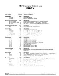
1 – Housing<br />
2 – Turbine Rotor<br />
3 – Rotor Supports<br />
4 – Magnetic Pick-up<br />
5 – Loading Valve<br />
6 – Pressure Sensor<br />
7 – Temperature Sensor<br />
8 – Pressure Relief<br />
Operating Principle<br />
Flo-<strong>tech</strong>’s portable hydraulic testers simultaneously<br />
measure the fl ow rate, temperature, pressure and,<br />
optionally, power of hydraulic fl uid. Designed for<br />
testing pumps, valves, cylinders, motors, hydrostatic<br />
or power shift transmissions, and power steering<br />
systems in both mobile and stationary applications,<br />
these <strong>com</strong>pact units utilize turbine fl ow meter<br />
<strong>tech</strong>nology.<br />
Flow: As fluid passes through the tester, it turns<br />
the turbine rotor. As each turbine blade passes the<br />
magnetic pick-up, an electrical signal is generated.<br />
This frequency signal is proportional to the fl ow<br />
rate and is transmitted to the tester’s electronics for<br />
display on a PC screen or the front panel LCD of the<br />
tester’s electronic case.<br />
Temperature: All testers contain an internal<br />
temperature sensor for measuring the temperature of<br />
the fl uid as it passes through the fl ow meter body.<br />
Portable Hydraulic Testers<br />
General Design Features<br />
RELIABLE FLOW MEASUREMENT<br />
3<br />
2<br />
4<br />
Pressure: Pressure is provided in either analog<br />
or digital format, depending on the model of the<br />
tester. PFM6 and PFM6BD testers are equipped<br />
with helical type pressure gauges, while the PFM8<br />
tester includes a silicon strain gauge pressure sensor<br />
and the Flo-Check USB tester utilizes a piezoelectric<br />
pressure sensor.<br />
Power: Power measurements are derived from<br />
the product of fl ow and pressure. The Flo-Check<br />
USB and the PFM8 are designed to calculate this<br />
measurement and display the results in either<br />
horsepower or kilowatts. When using the PFM6 or<br />
PFM6BD, power can be calculated using the following<br />
formulas:<br />
H.P. = GPM × PSI liters/min × Bar<br />
H.P. =<br />
1714<br />
447.4<br />
liters/min × Bar<br />
kW =<br />
600<br />
Designed for both ease of operation and safety, all<br />
testers feature loading valves with fi ngertip control<br />
and pressure surge protection.<br />
5<br />
7<br />
Fax 800-245-3569<br />
3
Flo-Check USB Hydraulic System Analyzer<br />
Simultaneously Measures Flow, Pressure and Temperature<br />
• Flow accuracy ± 1% of reading @ 32 cSt<br />
• Field selectable US or metric readings<br />
• High and low set point alarms for fl ow, pressure and<br />
temperature<br />
• Captures pressure spikes up to 10,000 PSI<br />
(0.2 milliseconds duration)<br />
® • Exports saved data to Microsoft Excel and other<br />
spreadsheet programs<br />
• USB powered<br />
• Easy to use, plug and play<br />
• Calculates hydraulic power<br />
• Select continuous monitoring or capture data manually<br />
• Logs up to 12 hours<br />
• Records alarm history<br />
The Flo-Check Hydraulic System Analyzer can be used<br />
as a stationary or portable tester for both industrial and<br />
mobile hydraulic system diagnostics, and analysis of the<br />
prognostic health of a hydraulic system. It features fl ow,<br />
pressure and temperature sensors that are monitored by a<br />
data acquisition module. This module records the operating<br />
parameters of the system and transfers them to the user’s<br />
laptop via the USB port.<br />
The custom software utility is a Windows ® -based application<br />
which is <strong>com</strong>patible with Windows Vista ® , Windows XP<br />
and Windows 2000. This intuitive software confi gures<br />
the displayed information into user-selected engineering<br />
units and provides real-time graphics with instantaneous<br />
readings and trends for all three measurement parameters.<br />
The software also permits the data to be saved for export<br />
into a spreadsheet program.<br />
The Hydraulic System Analyzer is powered through the USB<br />
port of a PC, making it easy to set up and ideal for portable<br />
applications. Interfaced to the PC application, the Hydraulic<br />
Analyzer offers a straightforward method of monitoring<br />
system parameters <strong>com</strong>plete with data acquisition.<br />
4<br />
Tel 800-433-5263<br />
SPECIFICATIONS<br />
Performance<br />
Flow:<br />
Accuracy ±1% of reading @ 32 cSt<br />
Repeatability ±0.2%<br />
Pressure:<br />
Accuracy
Flo-Check USB Hydraulic System Analyzer<br />
Simultaneously Measures Flow, Pressure and Temperature<br />
SOFTWARE<br />
The Flo-<strong>tech</strong> Analyzer software provides a real-time graphical<br />
and digital interface for monitoring and/or recording pressure,<br />
temperature and fl ow rate parameters from the Hydraulic Analyzer.<br />
In addition to the graphical and digital displays, the main screen<br />
also consists of a menu bar, buttons with <strong>com</strong>mon functions and<br />
alarm indicators.<br />
The software offers the following options:<br />
• View real time pressure, temperature, fl ow rate and power<br />
measurements<br />
• Record all measurements to a fi le<br />
• Choice of recording all measurement points or capturing<br />
points manually<br />
• Selection of all measurement units, US or metric<br />
• Ability to adjust display of graph data<br />
• High/Low alarm indicators set by the operator<br />
All measurements taken can be saved once<br />
per second to a <strong>com</strong>ma separated value (.csv)<br />
fi le for export into a spreadsheet program. For<br />
example, recording for 2 minutes would yield<br />
120 points of data. Even though data points<br />
are only recorded once per second, pressure<br />
spikes and dips are captured by recording the<br />
maximum or minimum pressure during each<br />
measurement period. Therefore, the precise<br />
shape of the pressure spike is not recorded<br />
but its amplitude and the time it occurred are<br />
both recorded.<br />
Measurement<br />
(over a 1 second<br />
time period)<br />
<strong>Co</strong>lor<br />
Indication<br />
Average Pressure Green<br />
Minimum Pressure Dark Green<br />
Maximum Pressure Dark Green<br />
Average Temperature Blue<br />
Average Flow Rate Yellow<br />
Average Power Orange<br />
Graphs<br />
The graph on the main screen contains more than 60 points of data. Previous data<br />
points are saved in memory and can be viewed at any time. Adjustments can be made<br />
to optimize data that is displayed by hiding individual graph plots, adjusting the scale<br />
of each plot or adding horizontal gridlines to the graph.<br />
Alarms<br />
There are three sets of High/Low alarm indicators on the main screen which monitor<br />
pressure, temperature and fl ow rate. Alarm indicators fl ash if the current system<br />
measurements exceed the alarm limits set by the operator and continue to fl ash<br />
when the current system measurements return to normal to alert the operator that an<br />
alarm condition occurred. Alarms must be reset manually to acknowledge the alarm<br />
condition.<br />
ORDERING INFORMATION<br />
MODEL NUMBER ¹ NOMINAL PORT SIZE FLOW RANGE<br />
F7164 SAE 12 2-30 GPM<br />
F7160 SAE 16 3 - 85 GPM<br />
F7161 SAE 24 7 - 199.9 GPM<br />
F7165 G 3/4 7.5 - 113.6 LPM<br />
F7162 G 1 15 - 321 LPM<br />
F7163 G 1-1/2 26 - 757 LPM<br />
¹ Each Flo-Check Hydraulic System Analyzer includes a 16.4 ft. (5 M) USB,<br />
A male to B male (IP 68) connection cable, CD-Rom of the software utility, and<br />
<strong>com</strong>plete operating instructions packaged in a protective carrying case.<br />
ACCESSORIES<br />
MODEL NUMBER DESCRIPTION<br />
TRACEABLE TO NIST STANDARDS<br />
Alarm<br />
Indication<br />
Digital<br />
Indication<br />
Graphical<br />
Display<br />
Fax 800-245-3569<br />
Record to<br />
File<br />
MODEL NUMBER DESCRIPTION<br />
F001109 5-Point Calibration Certifi cate ²<br />
F1614-7500 Pressure Relief Disc, 7500 PSI (1 per Tester)<br />
F001110 10-Point Calibration Certifi cate ² ² Certifi cates are traceable to NIST, ISO 9001.<br />
<br />
<br />
<br />
<br />
<br />
<br />
<br />
<br />
<br />
<br />
<br />
<br />
<br />
<br />
<br />
<br />
<br />
5
PFM6 Digital Portable Hydraulic Tester<br />
Simultaneously Measures Flow, Pressure and Temperature<br />
• Five fl ow ranges<br />
• Large 3-1/2 digit LCD for fl ow and<br />
temperature<br />
• Helical tube pressure gauge<br />
• One toggle switch to control power and<br />
select fl ow and temperature<br />
• Loading valve with fi ngertip control of<br />
pressure<br />
• Platinum resistance temperature sensor<br />
• Pressure surge protection<br />
• Turbine fl ow sensor provides fast response<br />
• Available with SAE or BSPP ports<br />
• Pressures up to 6000 PSI (414 Bar)<br />
• Temperatures up to 300 °F (150 °C)<br />
• Flow accuracy ±1% of full scale<br />
• Repeatability ±0.2%<br />
The PFM6 Series is a <strong>com</strong>pact, lightweight<br />
portable tester designed for fast diagnostic<br />
troubleshooting of all types of mobile or<br />
stationary hydraulic systems and <strong>com</strong>ponents.<br />
These self-contained testers feature laboratory<br />
accuracy and provide fl ow, pressure and<br />
temperature measurements simultaneously<br />
from one point.<br />
Simple operation includes a toggle switch to<br />
display either fl ow or temperature readings<br />
and a loading valve that operates with fi ngertip<br />
control. The dual scale helical tube pressure<br />
gauge offers pulsation dampening and high<br />
overpressure capacity. For safe operation, all<br />
testers include pressure surge protection.<br />
6<br />
Tel 800-433-5263<br />
SPECIFICATIONS<br />
Performance<br />
Flow Accuracy: ±1% of full scale<br />
Repeatability: ±0.2%<br />
Turbine Response:<br />
Temperature:<br />
≤200ms<br />
Fluid -4 to +300 °F (-20 to +150 °C)<br />
Ambient -4 to +131 °F (-20 to +55 °C)<br />
Flow Readout: Linearity and zero shift ±1 digit<br />
Operating Pressure: up to 6000 PSI (414 Bar,<br />
41.4 MPa, 420 kg/cm 2 )<br />
Pressure Drop: See ∆P charts on page 14<br />
Readout Accuracy: ±1 digit<br />
Material<br />
Housing: 6013-T651 Aluminum; anodized<br />
Turbine Rotor: T416 Stainless steel<br />
Ball Bearings: 440C Stainless steel<br />
Rotor Shaft: T303 Stainless steel<br />
Rotor Supports:<br />
PFM6-15/30 CA360 Brass<br />
PFM6-60/85/200 6061-T6 Aluminum alloy<br />
Hub <strong>Co</strong>nes: 6061-T6 Aluminum alloy<br />
Valve Body:<br />
PFM6-15/30 <strong>Co</strong>ld rolled steel; zinc plate,<br />
dichromate fi nish<br />
PFM6-60/85/200 12L14 Steel; zinc plate,<br />
dichromate fi nish<br />
Valve Stem: T303 Stainless steel<br />
Poppet: 12L14 Steel; hardened<br />
Sleeve:<br />
PFM6-200 only D.O.M. steel tube<br />
Temperature Probe: 12L14 Steel; zinc plate,<br />
dichromate fi nish<br />
Magnetic Pick-up:<br />
Body 12L14 Steel; black oxide fi nish<br />
Nut 12L14 Steel; zinc plate,<br />
dichromate fi nish<br />
Seals: Buna N standard;<br />
Viton ® and EPR optional<br />
Carrying Handle: Cast aluminum; anodized<br />
Electronic Case<br />
& <strong>Co</strong>ver: <strong>Co</strong>ld rolled steel; zinc plate with<br />
clear seal, epoxy black paint<br />
Battery: 4 AA size alkaline,<br />
~ 50 hours of service<br />
Ports: SAE Straight thread O-ring<br />
boss, female J1926/1;<br />
BSPP ISO1179<br />
HYDRAULIC SYSTEM DIAGNOSTIC TOOLS<br />
Viton is a registered trademark of DuPont Dow Elastomers.
DIMENSIONS<br />
ORDERING INFORMATION<br />
SERIES<br />
PFM6 Digital Portable Hydraulic Tester<br />
Simultaneously Measures Flow, Pressure and Temperature<br />
NOMINAL<br />
PORT SIZE<br />
FLOW<br />
RANGE<br />
MODEL<br />
NUMBER<br />
PFM6-15 SAE 12 1 - 15 GPM F5080 * - XXX<br />
PFM6-30 SAE 12 2 - 30 GPM F5079 * - XXX<br />
PFM6-60 SAE 16 3 - 60 GPM F5078 * - XXX<br />
PFM6-85 SAE 16 4 - 85 GPM F5077 * - XXX<br />
PFM6-200 SAE 24 7 - 199.9 GPM F5076 * - XXX<br />
PFM6-15 G 3/4 4 - 56 LPM F5110 * - XXX<br />
PFM6-30 G 3/4 7.5 - 113.6 LPM F5111 * - XXX<br />
PFM6-60 G 1 12 - 227 LPM F5112 * - XXX<br />
PFM6-85 G 1 15 - 321 LPM F5113 * - XXX<br />
PFM6-200 G 1-1/2 26 - 757 LPM F5114 * - XXX<br />
Examples:<br />
F5076-PSI = PFM6-200<br />
SAE 24 ports<br />
7 - 199.9 GPM fl ow range<br />
Standard model<br />
PSI pressure units<br />
ACCESSORIES<br />
MODEL<br />
NUMBER<br />
DESCRIPTION SERIES<br />
F4934-1530 Carrying Case PFM6-15 & PFM6-30<br />
F4934-6085 Carrying Case PFM6-60 & PFM6-85<br />
F4934-200 Carrying Case PFM6-200<br />
F1614-6000 Pressure Relief Disc, 6000 PSI (1 per Tester) All PFM6s<br />
F001109 5-Point Calibration Certifi cate ¹ All PFM6s<br />
F001110 10-Point Calibration Certifi cate ¹ All PFM6s<br />
¹ Certifi cates are traceable to NIST, ISO 9001.<br />
SERIES<br />
A<br />
LENGTH<br />
IN (mm)<br />
STD or CE MODEL<br />
Leave blank for<br />
standard model<br />
or<br />
CE for CE option<br />
FIVE OR TEN POINT CALIBRATION AVAILABLE<br />
B<br />
DEPTH<br />
IN (mm)<br />
C<br />
HEIGHT<br />
IN (mm)<br />
PRESSURE GAUGE<br />
UNITS OF MEASURE<br />
PSI<br />
BAR<br />
MPA<br />
KG/CM2<br />
F5111CE- BAR = PFM6-30<br />
G 3/4 ports<br />
7.5 - 113.6 LPM fl ow range<br />
CE certifi ed<br />
Bar pressure units<br />
Fax 800-245-3569<br />
WEIGHT<br />
LBS (KG)<br />
PFM6-15 11.3 (287) 3.5 (89) 11.0 (279) 13.85 (6.3)<br />
PFM6-30 11.3 (287) 3.5 (89) 11.0 (279) 13.85 (6.3)<br />
PFM6-60 11.5 (292) 3.5 (89) 11.0 (279) 16.50 (7.5)<br />
PFM6-85 11.5 (292) 3.5 (89) 11.0 (279) 16.50 (7.5)<br />
PFM6-200 12.3 (311) 4.0 (101) 11.8 (298) 20.00 (9.1)<br />
7
PFM6BD Bi-Directional Hydraulic Tester<br />
Simultaneously Measures Flow, Pressure and Temperature<br />
• Bi-directional in-line testing capabilities in<br />
three fl ow ranges<br />
• Large 3-1/2 digit LCD for fl ow and<br />
temperature<br />
• Helical tube pressure gauge<br />
• One toggle switch to control power and<br />
select fl ow and temperature<br />
• Loading valve with fi ngertip control of<br />
pressure<br />
• Platinum resistance temperature sensor<br />
• Pressure surge protection with internal<br />
pressure relief<br />
• Turbine fl ow sensor provides fast response<br />
• SAE ports<br />
• Pressures up to 6000 PSI (414 Bar)<br />
• Temperatures up to 300 °F (150 °C)<br />
• Forward fl ow accuracy ±1% of full scale<br />
• Repeatability ±0.2%<br />
The PFM6BD Series includes all the features<br />
of the standard PFM6 Series with the added<br />
benefi t of bi-directional fl ow measurement and<br />
an internal pressure relief system. Designed<br />
for fast diagnostic troubleshooting of all types<br />
of mobile or stationary hydraulic systems and<br />
<strong>com</strong>ponents, these <strong>com</strong>pact testers offer<br />
laboratory accuracy and provide fl ow, pressure<br />
and temperature measurements simultaneously<br />
from one point.<br />
8<br />
SPECIFICATIONS<br />
Tel 800-433-5263 RUGGED CONSTRUCTION<br />
Performance<br />
Flow Accuracy:<br />
Forward ±1% of full scale<br />
Reverse ±2% of full scale<br />
Repeatability: ±0.2%<br />
Turbine Response: ≤200ms<br />
Temperature:<br />
Fluid -4 to +300 °F (-20 to +150 °C)<br />
Ambient -4 to +131 °F (-20 to +55 °C)<br />
Flow Readout: Linearity and zero shift<br />
±1 digit<br />
Operating Pressure: up to 6000 PSI (414 Bar,<br />
41.4 MPa, 420 kg/cm 2 )<br />
Pressure Drop: See ∆P charts on page 14<br />
Readout Accuracy: ±1 digit<br />
Material<br />
Housing: 6013-T651 Aluminum; anodized<br />
Turbine Rotor: T416 Stainless steel<br />
Ball Bearings: 440C Stainless steel<br />
Rotor Shaft: T303 Stainless steel<br />
Rotor Supports: 6061-T6 Aluminum alloy<br />
Hub <strong>Co</strong>nes: 6061-T6 Aluminum alloy<br />
Valve Body: 12L14 Steel; zinc plate,<br />
dichromate fi nish<br />
Valve Stem: T303 Stainless steel<br />
Spool/Sleeve: 4340 Alloy steel; hardened<br />
Temperature Probe: 12L14 Steel; zinc plate,<br />
dichromate fi nish<br />
Magnetic Pick-up:<br />
Body 12L14 Steel; black oxide fi nish<br />
Nut 12L14 Steel; zinc plate,<br />
dichromate fi nish<br />
Seals: Buna N standard;<br />
Viton ® and EPR optional<br />
Carrying Handle: Cast aluminum; anodized<br />
Electronic Case<br />
& <strong>Co</strong>ver: <strong>Co</strong>ld rolled steel; zinc plate with<br />
clear seal, epoxy black paint<br />
Battery: 4 AA size alkaline,<br />
~ 50 hours of service<br />
Ports: SAE Straight thread O-ring<br />
boss, female J1926/1<br />
Viton is a registered trademark of DuPont Dow Elastomers.
DIMENSIONS<br />
ORDERING INFORMATION<br />
SERIES<br />
NOMINAL<br />
PORT SIZE<br />
FLOW<br />
RANGE<br />
MODEL<br />
NUMBER<br />
STD or CE<br />
MODEL<br />
PFM6BD-60 SAE 16 3 - 60 GPM (12 - 227 LPM) F5082 * - XXX Leave blank for<br />
PFM6BD-85 SAE 16 4 - 85 GPM (15 - 321 LPM) F5083 * - XXX<br />
standard model<br />
or<br />
PFM6BD-200 SAE 24 7 - 199.9 GPM (26 - 757 LPM) F5084 * - XXX CE for CE option<br />
Examples:<br />
PFM6BD Bi-Directional Hydraulic Tester<br />
Simultaneously Measures Flow, Pressure and Temperature<br />
F5083-PSI = PFM6BD-85<br />
SAE 16 ports<br />
4 - 85 GPM (15 - 321 LPM)<br />
Standard model<br />
PSI pressure units<br />
ACCESSORIES<br />
MODEL<br />
NUMBER<br />
DESCRIPTION SERIES<br />
F4934-6085 Carrying Case PFM6BD-60 & PFM6BD-85<br />
F4934-200 Carrying Case PFM6BD-200<br />
F1614-6000 Pressure Relief Disc, 6000 PSI (2 per Tester) All PFM6BDs<br />
F1614-7500 Pressure Relief Disc, 7500 PSI (1 per Tester) All PFM6BDs<br />
F001109 5-Point Calibration Certifi cate ¹ All PFM6s<br />
F001110 10-Point Calibration Certifi cate ¹ All PFM6s<br />
¹ Certifi cates are traceable to NIST, ISO 9001.<br />
SERIES<br />
DEPENDABLE CUSTOMER SERVICE<br />
A<br />
LENGTH<br />
IN (mm)<br />
B<br />
DEPTH<br />
IN (mm)<br />
C<br />
HEIGHT<br />
IN (mm)<br />
PRESSURE GAUGE<br />
UNITS OF MEASURE<br />
PSI<br />
BAR<br />
MPA<br />
KG/CM2<br />
F5082CE- PSI = PFM6BD-60<br />
SAE 16 ports<br />
3 - 60 GPM (12 - 227 LPM)<br />
CE certifi ed<br />
PSI pressure units<br />
Fax 800-245-3569<br />
WEIGHT<br />
LBS (KG)<br />
PFM6BD-60 11.3 (287) 4.0 (101) 11.0 (279) 16.50 (7.5)<br />
PFM6BD-85 11.3 (287) 4.0 (101) 11.0 (279) 16.50 (7.5)<br />
PFM6BD-200 11.8 (300) 4.5 (114) 11.5 (292) 19.50 (9.0)<br />
9
PFM8 Digital Hydraulic Tester & Dynamometer<br />
Simultaneously Measures Flow, Pressure, Power and Temperature<br />
• Five fl ow ranges<br />
• Front panel selectable US or metric readings<br />
• Dynamometer reads power (HP & kW) directly<br />
• 3-1/2 digit LCDs for digital display of fl ow,<br />
temperature, pressure and power<br />
• Large easy-to-use membrane switch<br />
• Loading valve with fi ngertip control of pressure<br />
• Silicon strain gauge pressure sensor<br />
• Platinum resistance temperature sensor<br />
• Pressure surge protection<br />
• Turbine fl ow sensor provides fast response<br />
• Pressures up to 6000 PSI (414 Bar)<br />
• Temperatures up to 300 °F (150 °C)<br />
• Flow accuracy ±1% of full scale<br />
• Repeatability ±0.2%<br />
The all digital PFM8 Series <strong>com</strong>bines a <strong>com</strong>pact,<br />
lightweight hydraulic tester and a dynamometer<br />
in one unit. Designed for fast diagnostic<br />
troubleshooting of all types of hydraulic systems and<br />
<strong>com</strong>ponents, including engine-pump <strong>com</strong>binations.<br />
These testers make all fl ow, temperature, pressure<br />
and power measurements from one point. A bonus<br />
feature of this series is the capability to switch from<br />
US to metric units of measure in the fi eld.<br />
Each tester utilizes two digital displays, one for fl ow<br />
and temperature and a second display for pressure<br />
and power. Simple operation includes a large format<br />
membrane switch for on/off control and selection of<br />
units of measure to be displayed. A loading valve<br />
with fi ngertip control and pressure surge protection<br />
are standard features.<br />
10<br />
SPECIFICATIONS<br />
Performance<br />
Flow Accuracy: ±1% of full scale<br />
Repeatability: ±0.2%<br />
Turbine Response:<br />
Temperature:<br />
≤200ms<br />
Fluid -4 to +300 °F (-20 to +150 °C)<br />
Ambient -4 to +131 °F (-20 to +55 °C)<br />
Flow Readout: Linearity and zero shift ±1 digit<br />
Operating Pressure: up to 6000 PSI (414 Bar,<br />
41.4 MPa, 420 kg/cm 2 )<br />
Pressure Drop: See ∆P charts on page 14<br />
Readout Accuracy: ±1 digit<br />
Tel 800-433-5263 RELIABLE FLOW MEASUREMENT<br />
Material<br />
Housing: 6013-T651 Aluminum; anodized<br />
Turbine Rotor: T416 Stainless steel<br />
Ball Bearings: 440C Stainless steel<br />
Rotor Shaft: T303 Stainless steel<br />
Rotor Supports:<br />
PFM6-15/30 CA360 Brass<br />
PFM6-60/85/200 6061-T6 Aluminum alloy<br />
Hub <strong>Co</strong>nes: 6061-T6 Aluminum alloy<br />
Valve Body:<br />
PFM6-15/30 <strong>Co</strong>ld rolled steel; zinc plate,<br />
dichromate fi nish<br />
PFM6-60/85/200 12L14 Steel; zinc plate,<br />
dichromate fi nish<br />
Valve Stem: T303 Stainless steel<br />
Poppet: 12L14 Steel; hardened<br />
Sleeve:<br />
PFM6-200 only D.O.M. steel tube<br />
Temperature Probe: 12L14 Steel; zinc plate,<br />
dichromate fi nish<br />
Magnetic Pick-up:<br />
Body 12L14 Steel; black oxide fi nish<br />
Nut 12L14 Steel; zinc plate,<br />
dichromate fi nish<br />
Seals: Buna N standard;<br />
Viton ® and EPR optional<br />
Carrying Handle: Cast aluminum; anodized<br />
Electronic Case<br />
& <strong>Co</strong>ver: <strong>Co</strong>ld rolled steel; zinc plate with<br />
clear seal, epoxy black paint<br />
Battery: AA size alkaline,<br />
~ 50 hours of service<br />
Ports: SAE Straight thread O-ring<br />
boss, female J1926/1;<br />
BSPP ISO1179<br />
Viton is a registered trademark of DuPont Dow Elastomers.
PFM8 Digital Hydraulic Tester & Dynamometer<br />
Simultaneously Measures Flow, Pressure, Power and Temperature<br />
DIMENSIONS<br />
ORDERING INFORMATION<br />
SERIES<br />
NOMINAL<br />
PORT SIZE<br />
FLOW<br />
RANGE<br />
POWER<br />
HP (kW)<br />
MODEL<br />
NUMBER<br />
PFM8-15 SAE 12 1 - 15 GPM (4 - 56 LPM) 52.5 (39) F5061<br />
PFM8-30 SAE 12 2 - 30 GPM (7.5 - 113.6 LPM) 105 (78) F5058<br />
PFM8-60 SAE 16 3 - 60 GPM (12 - 227 LPM) 210 (157) F5052<br />
PFM8-85 SAE 16 4 - 85 GPM (15 - 321 LPM) 298 (222) F5053<br />
PFM8-200 SAE 24 7 - 199.9 GPM (26 - 757 LPM) 700 (522) F5054<br />
Examples:<br />
F5061 = PFM8-15<br />
SAE 12 ports<br />
1 - 15 GPM (4 - 56 LPM)<br />
ACCESSORIES<br />
MODEL<br />
NUMBER<br />
DESCRIPTION SERIES<br />
F4934-1530 Carrying Case PFM8-15 & PFM8-30<br />
F4934-6085 Carrying Case PFM8-60 & PFM8-85<br />
F4934-200 Carrying Case PFM8-200<br />
F1614-6000 Pressure Relief Disc, 6000 PSI (1 per Tester) All PFM8s<br />
F001109 5-Point Calibration Certifi cate ¹ All PFM8s<br />
F001110 10-Point Calibration Certifi cate ¹ All PFM8s<br />
¹ Certifi cates are traceable to NIST, ISO 9001.<br />
SERIES<br />
TRACEABLE TO NIST STANDARDS<br />
A<br />
LENGTH<br />
IN (mm)<br />
B<br />
DEPTH<br />
IN (mm)<br />
C<br />
HEIGHT<br />
IN (mm)<br />
F5053 = PFM8-85<br />
SAE 16 ports<br />
4 - 85 GPM (15 - 321 LPM)<br />
Fax 800-245-3569<br />
WEIGHT<br />
LBS (KG)<br />
PFM8-15 11.3 (287) 3.5 (89) 11.0 (279) 13.85 (6.3)<br />
PFM8-30 11.3 (287) 3.5 (89) 11.0 (279) 13.85 (6.3)<br />
PFM8-60 11.5 (292) 3.5 (89) 11.0 (279) 16.50 (7.5)<br />
PFM8-85 11.5 (292) 3.5 (89) 11.0 (279) 16.50 (7.5)<br />
PFM8-200 12.3 (311) 4.0 (101) 11.8 (300) 20.00 (9.1)<br />
11
Sensor Array with Load Valve<br />
Simultaneously Measures Flow, Pressure and Temperature<br />
• Four fl ow ranges<br />
• Analog (4-20 mA or 0-5 VDC) or pulse output for<br />
fl ow rate<br />
• Silicon strain gauge pressure sensor with<br />
4-20 mA output<br />
• Platinum resistance temperature sensor with<br />
4-20 mA output<br />
• Loading valve with fi ngertip control of pressure<br />
• Pressure surge protection<br />
• Turbine fl ow sensor provides fast response<br />
• Pressures up to 6000 PSI (414 Bar)<br />
• Temperatures up to 300 °F (150 °C)<br />
• Flow accuracy ±1% of reading @ 32 cSt<br />
• Repeatability ±0.2%<br />
The Sensor Array is used for diagnostic evaluation<br />
of hydraulic motors, pumps, valves, hydrostatic<br />
drives and cylinders. When performed as part<br />
of a routine preventative maintenance program,<br />
catastrophic or untimely repairs are minimized.<br />
All that is required is to make quick and easy<br />
fl uid line connections between the sensing array<br />
and appropriate locations in the hydraulic circuit.<br />
The load valve is used to create a restriction so<br />
that a relief valve setting or internal leakage of a<br />
valve or hydraulic cylinder can be determined.<br />
The effi ciency of a hydraulic pump or motor can<br />
be similarly established and <strong>com</strong>pared to factory<br />
specifi cations.<br />
12<br />
SPECIFICATIONS<br />
Performance<br />
Flow Accuracy: ±1% of reading @ 32 cSt<br />
Repeatability:<br />
Temperature:<br />
±0.2%<br />
Fluid -4 to +300 °F (-20 to +150 °C)<br />
Ambient -4 to +131 °F (-20 to +55 °C)<br />
Operating Pressure: up to 6000 PSI (414 Bar, 41.4 MPa,<br />
420 kg/cm 2 )<br />
Pressure Drop: See ∆P charts on page 14<br />
IFC Signal <strong>Co</strong>nverter, Option: F to I F to V<br />
Power: Loop powered, 6V<br />
insertion loss max<br />
10 to 30 VDC<br />
10 to 30 VDC supply range<br />
Inputs: Magnetic Pick-up Magnetic Pick-up<br />
Frequency 0 to 3500 Hz 0 to 3500 Hz<br />
Trigger Sensitivity<br />
Frequency Measurement<br />
30 mV p-p 30 mV p-p<br />
Accuracy ±1% ±1%<br />
Analog Output: 4-20 mA current loop 0-5 VDC<br />
Resolution 1:4000 1:4000<br />
Temperature Drift 50 ppm / °C max 50 ppm / °C max<br />
Response 1.6 seconds min 1.6 seconds min<br />
Environmental:<br />
Ambient Temperature -22 to +158 °F -22 to +158 °F<br />
(-30 to +70 °C) (-30 to +70 °C)<br />
Humidity 0-90%, 0-90%,<br />
Magnetic Pick-up, Option:<br />
non-condensing non-condensing<br />
Electrical Output Signal Self-generating alternating pulse<br />
100 mV RMS (100 Hz) minimum<br />
Pressure Sensor:<br />
(optional)<br />
See page 26 for <strong>com</strong>plete specifi cations<br />
Temperature Sensor:<br />
(optional)<br />
Material<br />
See page 27 for <strong>com</strong>plete specifi cations<br />
Housing: 6013-T651 Aluminum; anodized<br />
Turbine Rotor: T416 Stainless steel<br />
Ball Bearings: 440C Stainless steel<br />
Rotor Shaft:<br />
Rotor Supports:<br />
T303 Stainless steel<br />
PFM6-15/30 CA360 Brass<br />
PFM6-85/200 6061-T6 Aluminum alloy<br />
Hub <strong>Co</strong>nes:<br />
Valve Body:<br />
6061-T6 Aluminum alloy<br />
PFM6-15/30 <strong>Co</strong>ld rolled steel; zinc plate, dichromate fi nish<br />
PFM6-85/200 12L14 Steel; zinc plate, dichromate fi nish<br />
Valve Stem: T303 Stainless steel<br />
Poppet:<br />
Sleeve:<br />
12L14 Steel; hardened<br />
PFM6-200 only D.O.M. steel tube<br />
Temperature Probe:<br />
Magnetic Pick-up:<br />
12L14 Steel; zinc plate, dichromate fi nish<br />
Body 12L14 Steel; black oxide fi nish<br />
Nut 12L14 Steel; zinc plate, dichromate fi nish<br />
Seals: Buna N standard;<br />
Viton ® and EPR optional<br />
Carrying Handle: Cast aluminum; anodized<br />
Ports: SAE Straight thread O-ring boss,<br />
female J1926/1; BSPP ISO1179<br />
Tel 800-433-5263 MEASURE SYSTEM PERFORMANCE<br />
Viton is a registered trademark of DuPont Dow Elastomers.
DIMENSIONS<br />
ORDERING INFORMATION<br />
NOMINAL<br />
PORT<br />
SIZE<br />
FLOW<br />
RANGE<br />
MODEL<br />
NUMBER<br />
SAE 12 1 - 15 GPM F6150<br />
SAE 12 2 - 30 GPM F6153<br />
SAE 16 4 - 85 GPM F6156<br />
SAE 24 7 - 199.9 GPM F6159<br />
G 3/4 4 - 56 LPM F6161<br />
G 3/4 7.5 - 113.6 LPM F6163<br />
G 1 15 - 321 LPM F6165<br />
G 1-1/2 26 - 757 LPM F6167<br />
FLOW<br />
TRANSDUCER<br />
F Frequency<br />
(Mag Pick-up)<br />
I 4-20 mA Out (IFC)<br />
V 0-5 VDC Out (IFC)<br />
Examples:<br />
F6150-I B - T 6 = SAE 12 ports<br />
1 - 15 GPM fl ow range<br />
4-20 mA output<br />
Buna N seals<br />
Temperature sensor<br />
6000 PSI (414 Bar) pressure sensor<br />
ACCESSORIES<br />
MODEL<br />
NUMBER<br />
Sensor Array with Load Valve<br />
Simultaneously Measures Flow, Pressure and Temperature<br />
DESCRIPTION SERIES<br />
F1614-6000 Pressure Relief Disc, 6000 PSI (1 per Sensor)<br />
F001109 5-Point Calibration Certifi cate ¹<br />
F001110 10-Point Calibration Certifi cate ¹<br />
¹ Certifi cates are traceable to NIST, ISO 9001.<br />
SEALS TEMPERATURE PRESSURE<br />
B Buna N<br />
V Viton ®<br />
E EPR<br />
T with Sensor<br />
G G 1/4 (F) Plugged<br />
0 SAE 2 (J514) Plugged<br />
1 1000 PSI (69 Bar) Sensor<br />
3 3000 PSI (207 Bar) Sensor<br />
5 5000 PSI (345 Bar) Sensor<br />
6 6000 PSI (414 Bar) Sensor<br />
G G 1/4 (F) Plugged<br />
0 1/4 NPTF (F) Plugged<br />
F6165-F V- G 5 = G 1 ports<br />
15 - 321 LPM fl ow range<br />
Frequency output<br />
Viton ® seals<br />
G 1/4 (F) plugged temp port<br />
5000 PSI (345 Bar) pressure sensor<br />
All<br />
Sensor<br />
Arrays<br />
MODEL<br />
A<br />
LENGTH<br />
IN (mm)<br />
FIVE OR TEN POINT CALIBRATION AVAILABLE<br />
B<br />
DEPTH<br />
IN (mm)<br />
C<br />
HEIGHT<br />
IN (mm)<br />
For information about Refer to<br />
Digital Displays Form No. 549<br />
Pressure Sensors Page 26<br />
Temperature Sensor Page 27<br />
Cables Pages 28 & 29<br />
Viton is a registered trademark of DuPont Dow Elastomers.<br />
Fax 800-245-3569<br />
WEIGHT<br />
LBS (KG)<br />
F6150 / F6161 11.3 (287) 3.5 (89) 11.0 (279) 13.85 (6.3)<br />
F6153 / F6163 11.3 (287) 3.5 (89) 11.0 (279) 13.85 (6.3)<br />
F6156 / F6165 11.5 (292) 3.5 (89) 11.0 (279) 16.50 (7.5)<br />
F6159 / F6167 11.5 (292) 3.5 (89) 11.0 (279) 16.50 (7.5)<br />
13
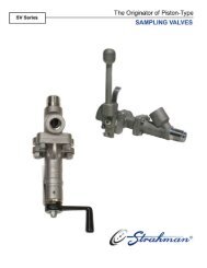
Flow vs Pressure Drop Charts<br />
Flo-Check USB, PFM Series and F6100 Sensor Arrays<br />
PRESSURE DROP PSI<br />
PRESSURE DROP PSI<br />
PRESSURE DROP PSI<br />
PRESSURE DROP PSI<br />
60<br />
50<br />
40<br />
30<br />
20<br />
10<br />
60<br />
50<br />
40<br />
30<br />
20<br />
10<br />
30<br />
25<br />
20<br />
15<br />
10<br />
PFM6-15, PFM8-15, F6150, F6161<br />
0 0 5 10 15 20<br />
FLOW GPM<br />
PFM6-60, PFM8-60<br />
0 0 10 20 30 40 50 60 70<br />
5<br />
FLOW GPM<br />
PFM6 - 200, PFM8 -200, F6159, F6167<br />
0<br />
0 20 40 60 80 100 120 140 160 180 200 220<br />
FLOW GPM<br />
60<br />
50<br />
40<br />
30<br />
20<br />
10<br />
PFM6BD - 85, F7160, F7162<br />
0<br />
0 10 20 30 40 50 60 70 80 90 100<br />
FLOW GPM<br />
FORWARD<br />
REVERSE<br />
14 Tel 800-433-5263 TRACEABLE TO NIST STANDARDS<br />
PRESSURE DROP PSI<br />
PRESSURE DROP PSI<br />
PRESSURE DROP PSI<br />
PRESSURE DROP PSI<br />
30<br />
25<br />
20<br />
15<br />
10<br />
5<br />
120<br />
100<br />
PFM6 - 30, PFM8 - 30, F6153, F6163<br />
0 0 10 20 30 40<br />
80<br />
60<br />
40<br />
20<br />
FLOW GPM<br />
PFM6 - 85, PFM8- 85, F6156, F6165<br />
0<br />
0 10 20 30 40 50 60 70 80 90 100<br />
FLOW GPM<br />
120<br />
100<br />
80<br />
60<br />
40<br />
20<br />
PFM6BD - 60<br />
0<br />
0 10 20 30 40 50 60 70<br />
FLOW GPM<br />
40<br />
35<br />
30<br />
25<br />
20<br />
15<br />
10<br />
5<br />
PFM6BD - 200, F7161, F7163<br />
0<br />
0 20 40 60 80 100 120 140 160 180 200 220<br />
FLOW GPM<br />
FORWARD<br />
REVERSE<br />
FORWARD<br />
REVERSE
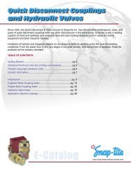
1 – Housing<br />
2 – Turbine Rotor<br />
3 – Rotor Supports<br />
4 – Lock Nut<br />
5 – Magnetic Pick-up (frequency output)<br />
Operating Principle<br />
Turbine fl ow sensors measure the fl ow rate of hydraulic<br />
fl uid and <strong>com</strong>patible liquids. As fl uid fl ows through the<br />
sensor it turns the turbine rotor, and as the turbine blades<br />
pass the magnetic pick-up a frequency signal is generated.<br />
This frequency signal is proportional to the fl ow rate<br />
and can be transmitted to Flo-<strong>tech</strong>’s digital displays or<br />
converted to an analog output. Optional sensors allow<br />
measurement of pressure and temperature.<br />
Rugged <strong>Co</strong>nstruction: Flow sensors are constructed of<br />
anodized aluminum and Stressproof ® steel with SAE; BSPP;<br />
<strong>Co</strong>de 61; and <strong>Co</strong>de 62, 4-bolt fl anged ports. The fl ow sensors<br />
have a fl uid temperature range of -4 to +300 °F, and are<br />
available in pressure ratings up to 6000 PSI.<br />
Flow Straighteners: While fl ow straighteners are<br />
manufactured into each sensor, it is re<strong>com</strong>mended that<br />
at least 10 port diameters of upstream pipe with no<br />
obstructions to the fl ow sensor and at least 5 port diameters<br />
downstream pipe be provided to obtain laminar fl ow.<br />
Filtration: All applications should be fi ltered to at least<br />
40 micron. Placing the fl ow sensor at a higher elevation<br />
in the system will avoid collection of debris, sediment, and<br />
dirt in the sensor.<br />
Bi-directional fl ow capability: Turbine fl ow sensors<br />
are inherently bi-directional, as the turbine will function<br />
normally in reverse condition. Flo-<strong>tech</strong> does not guarantee<br />
accuracy in reverse fl ow. However, it is generally in the<br />
range of ±1.5% to ±2% full scale. If required, a reverse<br />
fl ow calibration is optional.<br />
Turbine Flow Sensors<br />
General Design Features<br />
6 – Signal <strong>Co</strong>nverter (analog output)<br />
7 – Pressure Port Adapter<br />
8 – Temperature Port Adapter<br />
9 – Retaining Rings<br />
HYDRAULIC SYSTEM DIAGNOSTIC TOOLS<br />
Accuracy: The fl ow sensors have a forward fl ow accuracy<br />
of ±1% full scale while monitoring hydraulic liquids with<br />
viscosity and specifi c gravity similar to factory calibrated<br />
fl uids. Flow sensors that include the Intelligent Frequency<br />
<strong>Co</strong>nverter (IFC) are capable of even greater accuracy.<br />
Repeatability: Flow sensor repeatability is within ±0.2%.<br />
This is particularly important in cyclical applications which<br />
require consistent readings.<br />
Linearization: When used with the Intelligent Frequency<br />
<strong>Co</strong>nverter (IFC) and/or Flo-<strong>tech</strong> digital displays, accuracy<br />
can be improved by up to 4 times through the linearization<br />
of 10 points of fl ow data.<br />
Calibration: Flow sensors are calibrated with 0.876<br />
specifi c gravity, 150 SUS (32 cSt) hydraulic oil, irrespective<br />
of fi nal fl uid use. Three points of calibration data are<br />
provided with each turbine fl ow sensor. Optional 5- and<br />
10-point calibration certifi cation is also available.<br />
Viscosity: The functional range of the turbine fl ow<br />
sensors is approximately 25 to 500 SUS (2 to 110 cSt).<br />
However, in order for the fl ow sensors to maintain their<br />
±1% full scale accuracy rating, the fl uid must stay within<br />
10 cSt of the calibrated viscosity.<br />
Stressproof is a registered trademark of Niagara LaSalle <strong>Co</strong>rporation.<br />
Fax 800-245-3569<br />
15
Activa Sensor Array<br />
Simultaneously Measures Flow, Pressure and Temperature<br />
• Four fl ow ranges<br />
• Turbine fl ow measurement<br />
• IFC converter with 4-20 mA or 0-5 VDC output<br />
for fl ow rate<br />
• 4-20 mA output for temperature and pressure<br />
• Pressures up to 5800 PSI (400 Bar)<br />
• Temperatures up to 300 °F (150 °C)<br />
• Available with SAE or BSPP ports<br />
• Flow accuracy ±1% of reading @ 32 cSt<br />
• Repeatability ±0.2%<br />
The Activa Sensor Array provides fl ow,<br />
temperature and pressure signals in a <strong>com</strong>pact<br />
unit that requires only one hydraulic line break.<br />
Each sensor transmits an output signal that is<br />
easily integrated with PCs, PLCs, recorders or<br />
panel displays. Signals can also be transmitted to<br />
Flo-<strong>tech</strong>’s F6700/F6750 Series digital displays.<br />
Typical applications include fl uid characteristic<br />
measurement on test stands, stationary hydraulic<br />
system monitoring, feedback for hydraulic<br />
system control, advance warning of impending<br />
<strong>com</strong>ponent failure and mobile hydraulic system<br />
diagnosis.<br />
Viton is a registered trademark of DuPont Dow Elastomers.<br />
16<br />
SPECIFICATIONS<br />
Performance<br />
Forward Flow Accuracy: ±1% of reading @ 32 cSt<br />
Repeatability:<br />
Temperature ¹:<br />
±0.2%<br />
Fluid -4 to +300 °F (-20 to +150 °C)<br />
Ambient -4 to +131 °F (-20 to +55 °C)<br />
Operating Pressure: up to 5800 PSI (400 Bar) maximum<br />
Pressure Drop: See ∆P charts on page 24<br />
Readout Accuracy: ±1 digit<br />
IFC Signal <strong>Co</strong>nverter: F to I F to V<br />
Power: Loop powered, 6V<br />
insertion loss max<br />
10 to 30 VDC<br />
10 to 30 VDC supply range<br />
Inputs: Magnetic Pick-up Magnetic Pick-up<br />
Frequency 0 to 3500 Hz 0 to 3500 Hz<br />
Trigger Sensitivity<br />
Frequency Measurement<br />
30 mV p-p 30 mV p-p<br />
Accuracy ±1% ±1%<br />
Analog Output: 4-20 mA current loop 0-5 VDC<br />
Resolution 1:4000 1:4000<br />
Temperature Drift 50 ppm / °C max 50 ppm / °C max<br />
Response 1.6 seconds min 1.6 seconds min<br />
Environmental:<br />
Ambient Temperature -22 to +158 °F -22 to +158 °F<br />
(-30 to +70 °C) (-30 to +70 °C)<br />
Humidity 0-90%, 0-90%,<br />
non-condensing non-condensing<br />
Pressure Sensor:<br />
(optional)<br />
See page 26 for <strong>com</strong>plete specifi cations<br />
Temperature Sensor:<br />
(optional)<br />
Material<br />
See page 27 for <strong>com</strong>plete specifi cations<br />
Housing: 6013-T651 Aluminum; anodized<br />
Turbine Rotor: T416 Stainless steel<br />
Ball Bearings: 440C Stainless steel<br />
Rotor Shaft: T303 Stainless steel<br />
Rotor Supports: 6061-T6 Aluminum alloy<br />
F6202 & F6222 CA360 Brass<br />
Hub <strong>Co</strong>nes:<br />
F6204, F6206, F6208,<br />
6061-T6 Aluminum alloy<br />
F6224, F6226 & F6228 only<br />
Adapters: 6061-T6 Aluminum; anodized<br />
Retaining Rings: 6061-T6 Aluminum alloy<br />
Seals: Buna N standard;<br />
Viton ® and EPR optional<br />
IFC (includes magnetic pick-up):<br />
Pick-up Body 12L14 Steel; black oxide fi nish<br />
Pick-up Nut 12L14 Steel; zinc plate, dichromate fi nish<br />
IFC Case 6061-T6 Aluminum; nickel-plated<br />
IFC <strong>Co</strong>nnector Brass; nickel-plated<br />
Ports: SAE J1926/1; BSPP ISO1179<br />
¹ When an optional pressure sensor is installed, the temperature range will be limited to<br />
the specifi cations for that device.<br />
Tel 800-433-5263 MEASURE SYSTEM PERFORMANCE
DIMENSIONS<br />
MODEL<br />
A<br />
WIDTH<br />
IN (mm)<br />
B<br />
LENGTH<br />
IN (mm)<br />
C<br />
HEIGHT<br />
IN (mm)<br />
D<br />
w/IFC<br />
IN (mm)<br />
WEIGHT<br />
LBS (KG)<br />
F6202-A / F6222-A 1.23 (31.2) 4.72 (120.0) 1.47 (37.3) 5.18 (131.5) 1.60 (0.73)<br />
F6204-A / F6224-A 1.48 (37.6) 5.08 (129.0) 1.80 (45.7) 5.46 (138.7) 1.90 (0.86)<br />
F6206-A / F6226-A 1.98 (50.3) 5.87 (149.0) 2.20 (56.0) 6.07 (154.2) 2.80 (1.27)<br />
F6208-A / F6228-A 2.46 (62.5) 6.81 (173.0) 2.48 (63.0) 6.37 (161.8) 4.20 (1.91)<br />
ORDERING INFORMATION<br />
NOMINAL<br />
PORT<br />
SIZE<br />
FLOW<br />
RANGE<br />
MODEL<br />
NUMBER<br />
SAE 8 0.4 - 7 GPM F6202-A<br />
SAE 12 2 - 40 GPM F6204-A<br />
SAE 16 4 - 80 GPM F6206-A<br />
SAE 20 8 - 160 GPM F6208-A<br />
G 1/4 1.5 - 26 LPM F6222-A<br />
G 3/4 7.5 - 151 LPM F6224-A<br />
G 1 15 - 302 LPM F6226-A<br />
FLOW<br />
TRANSDUCER<br />
I 4-20 mA Out (IFC)<br />
V 0-5 VDC Out (IFC)<br />
Examples:<br />
F6204-AI B - T 6 = SAE 12 ports<br />
2 - 40 GPM fl ow range<br />
4-20 mA output<br />
Buna N seals<br />
Temperature sensor<br />
6000 PSI (414 Bar) pressure sensor<br />
Activa Sensor Array<br />
Simultaneously Measures Flow, Pressure and Temperature<br />
SEALS TEMPERATURE PRESSURE<br />
B Buna N<br />
V Viton ®<br />
E EPR<br />
T with Sensor<br />
N 1/4 NPTF (F) Plugged<br />
S SAE 2 (J514) Plugged<br />
G G 1/4 (F) Plugged<br />
D SAE 4 Plugged<br />
1 1000 PSI (69 Bar) Sensor<br />
3 3000 PSI (207 Bar) Sensor<br />
5 5000 PSI (345 Bar) Sensor<br />
6 6000 PSI (414 Bar) Sensor ²<br />
N 1/4 NPTF (F) Plugged<br />
S SAE 2 (J514) Plugged<br />
F G 1/4 (F) Plugged<br />
G 1-1/4 30 - 605 LPM F6228-A ² Not available with Models F6208 or F6228<br />
ACCESSORIES<br />
MODEL NUMBER DESCRIPTION<br />
F001109 5-Point Calibration Certifi cate ³<br />
F001110 10-Point Calibration Certifi cate ³<br />
³ Certifi cates are traceable to NIST, ISO 9001.<br />
DEPENDABLE CUSTOMER SERVICE<br />
F6228-AV V- G 5 = G 1-1/4 ports<br />
30 - 605 LPM fl ow range<br />
0-5 VDC output<br />
Viton ® seals<br />
G 1/4 (F) plugged temp port<br />
5000 PSI (345 Bar) pressure sensor<br />
For information about Refer to<br />
Digital Displays Form No. 549<br />
Pressure Sensors Page 26<br />
Temperature Sensor Page 27<br />
Cables Pages 28 & 29<br />
Viton is a registered trademark of DuPont Dow Elastomers.<br />
Fax 800-245-3569<br />
17
Ultima Sensor Array<br />
Simultaneously Measures Flow, Pressure and Temperature<br />
• Four fl ow ranges<br />
• Turbine fl ow measurement<br />
• Standard magnetic pick-up with frequency<br />
output for fl ow rate<br />
• 4-20 mA output for temperature and pressure<br />
• Pressures up to 5800 PSI (400 Bar)<br />
• Temperatures up to 300 °F (150 °C)<br />
• Available with SAE or BSPP ports<br />
• Flow accuracy ±1% of full scale<br />
• Repeatability ±0.2%<br />
The Ultima Sensor Array provides fl ow,<br />
temperature and pressure signals in a <strong>com</strong>pact<br />
unit that requires only one hydraulic line break.<br />
The magnetic pick-up generates a frequency<br />
output for fl ow rate measurement while the<br />
pressure and temperature sensors provide<br />
4-20 mA output signals. The fl ow signals can be<br />
transmitted to Flo-<strong>tech</strong>’s F6600/F6650 Series,<br />
and the temperature and pressure signals can<br />
be transmitted to the F6700/F6750 Series digital<br />
displays or any other instruments that accept a<br />
frequency or 4-20 mA signal.<br />
Typical applications include fl uid characteristic<br />
measurement on test stands, stationary hydraulic<br />
system monitoring, feedback for hydraulic<br />
system control, advance warning of impending<br />
<strong>com</strong>ponent failure and mobile hydraulics system<br />
diagnosis.<br />
18<br />
SPECIFICATIONS<br />
Performance<br />
Forward Flow<br />
Accuracy: ±1% of full scale<br />
(±1% of rate when used with<br />
F6600/F6650 display)<br />
Repeatability: ±0.2%<br />
Turbine Response: ≤200ms<br />
Temperature:<br />
Fluid -4 to +300 °F (-20 to +150 °C)<br />
Ambient -4 to +131 °F (-20 to +55 °C)<br />
Operating Pressure: up to 5800 PSI (400 Bar) max<br />
Pressure Drop: See ∆P charts on page 24<br />
Readout Accuracy: ±1 digit<br />
Magnetic Pick-up:<br />
Electrical Output<br />
Signal Self-generating alternating pulse<br />
100 mV RMS (100 Hz) minimum<br />
F6202 & F6222 10 mV RMS (200 Hz) minimum<br />
Pressure Sensor: See page 26 for<br />
(optional) <strong>com</strong>plete specifi cations<br />
Temperature Sensor: See page 27 for<br />
(optional) <strong>com</strong>plete specifi cations<br />
Material<br />
Housing: 6013-T651 Aluminum; anodized<br />
Turbine Rotor: T416 Stainless steel<br />
Ball Bearings: 440C Stainless steel<br />
Rotor Shaft: T303 Stainless steel<br />
Rotor Supports: 6061-T6 Aluminum alloy<br />
F6202 & F6222 CA360 Brass<br />
Hub <strong>Co</strong>nes: 6061-T6 Aluminum alloy<br />
F6204, F6206, F6208,<br />
F6224, F6226 & F6228 only<br />
Adapters: 6061-T6 Aluminum; anodized<br />
Retaining Rings: 6061-T6 Aluminum alloy<br />
Seals: Buna N standard;<br />
Viton ® and EPR optional<br />
Magnetic Pick-up:<br />
Body 12L14 Steel; black oxide fi nish<br />
Nut 12L14 Steel; zinc plate,<br />
dichromate fi nish<br />
Ports: SAE J1926/1; BSPP ISO1179<br />
Tel 800-433-5263 RELIABLE FLOW MEASUREMENT<br />
Viton is a registered trademark of DuPont Dow Elastomers.
DIMENSIONS<br />
MODEL<br />
A<br />
WIDTH<br />
IN (mm)<br />
B<br />
LENGTH<br />
IN (mm)<br />
C<br />
HEIGHT<br />
IN (mm)<br />
D<br />
w/MAG<br />
IN (mm)<br />
WEIGHT<br />
LBS (KG)<br />
F6202-F / F6222-F 1.23 (31.2) 4.72 (120.0) 1.47 (37.3) 3.72 (94.5) 1.55 (0.70)<br />
F6204-F / F6224-F 1.48 (37.6) 5.08 (129.0) 1.80 (45.7) 4.05 (102.9) 1.75 (0.79)<br />
F6206-F / F6226-F 1.98 (50.3) 5.87 (149.0) 2.20 (56.0) 4.46 (113.3) 2.75 (1.25)<br />
F6208-F / F6228-F 2.46 (62.5) 6.81 (173.0) 2.48 (63.0) 4.75 (120.7) 4.10 (1.86)<br />
ORDERING INFORMATION<br />
NOMINAL<br />
PORT SIZE<br />
FLOW<br />
RANGE<br />
MODEL<br />
NUMBER<br />
SAE 8 0.4 - 7 GPM F6202-F 1<br />
SAE 12 2 - 40 GPM F6204-F<br />
SAE 16 4 - 80 GPM F6206-F<br />
SAE 20 8 - 160 GPM F6208-F<br />
G 1/4 1.5 - 26 LPM F6222-F 1<br />
G 3/4 7.5 - 151 LPM F6224-F<br />
G 1 15 - 302 LPM F6226-F<br />
G 1-1/4 30 - 605 LPM F6228-F<br />
Examples:<br />
F6204-FB - T 6 = SAE 12 ports<br />
2 - 40 GPM fl ow range<br />
4-20 mA output<br />
Buna N seals<br />
Temperature sensor<br />
6000 PSI (414 Bar) pressure sensor<br />
ACCESSORIES<br />
MODEL NUMBER DESCRIPTION<br />
F001109 5-Point Calibration Certifi cate 3<br />
F001110 10-Point Calibration Certifi cate 3<br />
3 Certifi cates are traceable to NIST, ISO 9001.<br />
Ultima Sensor Array<br />
Simultaneously Measures Flow, Pressure and Temperature<br />
SEALS TEMPERATURE PRESSURE<br />
B Buna N<br />
V Viton ®<br />
E EPR<br />
T with Sensor<br />
N 1/4 NPTF (F) Plugged<br />
S SAE 2 (J514) Plugged<br />
G G 1/4 (F) Plugged<br />
D SAE 4 Plugged<br />
1 1000 PSI (69 Bar) Sensor<br />
3 3000 PSI (207 Bar) Sensor<br />
5 5000 PSI (345 Bar) Sensor<br />
6 6000 PSI (414 Bar) Sensor 2<br />
N 1/4 NPTF (F) Plugged<br />
S SAE 2 (J514) Plugged<br />
F G 1/4 (F) Plugged<br />
2 Not available with Models F6208 or F6228<br />
1 F6202 -F and F6222-F require K-Factor Scaler, F5140 (see page 25), to amplify frequency signal to be <strong>com</strong>patible with Flo-<strong>tech</strong>’s F6600/F6650 Digital Displays.<br />
TRACEABLE TO NIST STANDARDS<br />
F6228-FV- G 5 = G 1-1/4 ports<br />
30 - 605 LPM fl ow range<br />
0-5 VDC output<br />
Viton ® seals<br />
G 1/4 (F) plugged temp port<br />
5000 PSI (345 Bar) pressure sensor<br />
For information about Refer to<br />
Digital Displays Form No. 549<br />
Pressure Sensors Page 26<br />
Temperature Sensor Page 27<br />
Cables Pages 28 & 29<br />
Viton is a registered trademark of DuPont Dow Elastomers.<br />
Fax 800-245-3569<br />
19
Classic Turbine Flow Sensor<br />
Measures Flow Rate Providing Frequency or Analog Output<br />
• Choice of high strength aluminum or<br />
Stressproof ® steel bodies<br />
• Turbine fl ow measurement<br />
• Flow accuracy ±1% of full scale<br />
• Repeatability ±0.2%<br />
• Pressures up to 6000 PSI (414 Bar)<br />
• Temperatures up to 300 °F (150 °C)<br />
• Optional IFC converter provides analog output<br />
Flo-<strong>tech</strong>’s Classic Turbine Flow Sensors measure<br />
the fl ow rate of hydraulic fl uids and other <strong>com</strong>patible<br />
liquids. Offered in a choice of high strength<br />
anodized aluminum or Stressproof ® steel<br />
bodies, these durable fl ow sensors are capable<br />
of withstanding pressures up to 6000 PSI (414<br />
Bar).<br />
The Classic Series with the standard magnetic<br />
pick-up provides a frequency signal that is<br />
proportional to fl ow rate and can be transmitted to<br />
Flo-<strong>tech</strong>’s F6600/F6650 Series digital displays. If<br />
an analog output is preferred, these sensors are<br />
also available with the IFC (Intelligent Frequency<br />
<strong>Co</strong>nverter) which offers either a 4-20 mA or<br />
0-5 VDC output signal, allowing easy integration<br />
with Flo-<strong>tech</strong>’s F6700/F6750 Series digital<br />
displays, PCs, PLCs or other data acquisition<br />
devices.<br />
Viton is a registered trademark of DuPont Dow Elastomers.<br />
Stressproof is a registered trademark of Niagara LaSalle <strong>Co</strong>rporation.<br />
20<br />
Tel 800-433-5263 RUGGED CONSTRUCTION<br />
SPECIFICATIONS<br />
Performance<br />
Forward Flow Accuracy:<br />
Magnetic pick-up ±1% of full scale (±1% of rate when<br />
used with F6600/F6650 display)<br />
IFC option ±1% of reading @ 32 cSt<br />
Repeatability: ±0.2%<br />
Turbine Response:<br />
Temperature:<br />
≤200ms<br />
Fluid -4 to +300 °F (-20 to +150 °C)<br />
Ambient<br />
Operating Pressure:<br />
-4 to +131 °F (-20 to +55 °C)<br />
FSC, FSB Series 5000 PSI (345 Bar) maximum<br />
FSD Series 6000 PSI (414 Bar) maximum<br />
Pressure Drop: See ∆P charts on page 24<br />
Magnetic Pick-up, Standard:<br />
Electrical Output Signal Self-generating alternating pulse<br />
100 mV RMS (100 Hz) minimum<br />
FSC-375 Series 10 mV RMS (200 Hz) minimum<br />
IFC Signal <strong>Co</strong>nverter, Optional: F to I F to V<br />
Power: Loop powered, 6V<br />
insertion loss max<br />
10 to 30 VDC<br />
10 to 30 VDC supply range<br />
Inputs: Magnetic Pick-up Magnetic Pick-up<br />
Frequency 0 to 3500 Hz 0 to 3500 Hz<br />
Trigger Sensitivity<br />
Frequency Measurement<br />
30 mV p-p 30 mV p-p<br />
Accuracy ±1% ±1%<br />
Analog Output: 4-20 mA current loop 0-5 VDC<br />
Resolution 1:4000 1:4000<br />
Temperature Drift 50 ppm / °C max 50 ppm / °C max<br />
Response<br />
Environmental:<br />
1.6 seconds min 1.6 seconds min<br />
Ambient Temperature -22 to +158 °F -22 to +158 °F<br />
(-30 to +70 °C) (-30 to +70 °C)<br />
Humidity 0-90%, 0-90%,<br />
Material<br />
non-condensing non-condensing<br />
Housing: 6013-T651 Aluminum; anodized<br />
FSD Series Stressproof ® steel; zinc plate,<br />
dichromate fi nish<br />
Turbine Rotor: T416 Stainless steel<br />
Bearings: 440C Stainless steel ball bearings<br />
FSD Series Tungsten carbide journal bearings<br />
Rotor Shaft: T303 Stainless steel<br />
FSD Series Tungsten carbide<br />
Rotor Supports: 6061-T6 Aluminum alloy<br />
FSC-375, 500, 750 CA360 Brass<br />
FSD Series T303 Stainless steel<br />
Hub <strong>Co</strong>nes:<br />
FSC-500, 750, 1000, 1005<br />
& FSB-1250, 1500 only<br />
6061-T6 Aluminum alloy<br />
Retaining Rings: Steel; zinc plate<br />
FSC-375 Series T303 Stainless steel<br />
Seals: Buna N standard;<br />
Viton ® and EPR optional<br />
Magnetic Pick-up, Standard:<br />
Body 12L14 Steel; black oxide fi nish<br />
Nut 12L14 Steel; zinc plate, dichromate fi nish<br />
IFC (includes magnetic pick-up), Optional:<br />
Case 6061-T6 Aluminum; nickel plate<br />
<strong>Co</strong>nnector Brass; nickel plate<br />
Ports SAE J1926/1,<br />
<strong>Co</strong>de 61 and <strong>Co</strong>de 62: SAE J518
DIMENSIONS<br />
FSC<br />
Magnetic Pickup<br />
Housing<br />
SERIES<br />
B<br />
A<br />
WIDTH<br />
IN (mm)<br />
ORDERING INFORMATION<br />
NOMINAL<br />
PORT SIZE<br />
FLOW RANGE<br />
GPM (LPM)<br />
Examples:<br />
F2084-ASCM = SAE 16 ports<br />
3 - 60 GPM (11.5 - 227 LPM)<br />
Frequency output<br />
Buna N seals<br />
ACCESSORIES<br />
Classic Turbine Flow Sensor<br />
Measures Flow Rate Providing Frequency or Analog Output<br />
SERIES<br />
MODEL NUMBER<br />
Frequency Output<br />
MODEL NUMBER<br />
4-20 mA Output<br />
MODEL NUMBER<br />
0-5 VDC Output<br />
SAE 8 0.4 - 7 (1.5 - 26) FSC-375 F2945-ASCM ² F2945-ASCI F2945-ASCV<br />
SAE 12 1 - 15 (4 - 56) FSC-500 F2082-ASCM F2082-ASCI F2082-ASCV<br />
SAE 12 2 - 25 (7.5 - 94) FSC-750 F2083-ASCM F2083-ASCI F2083-ASCV<br />
SAE 16 3 - 60 (11.5 - 227) FSC-1000 F2084-ASCM F2084-ASCI F2084-ASCV<br />
SAE16 4 - 85 (15 - 321) FSC-1005 F2084-ASCM8 F2084-ASCI8 F2084-ASCV8<br />
SAE 20, <strong>Co</strong>de 61, 4-Bolt Face 5 - 100 (20 - 378) FSB-1250 F2085-ASBM F2085-ASBI F2085-ASBV<br />
SAE 24, <strong>Co</strong>de 61, 4-Bolt Face 7 - 200 (27 - 757) FSB-1500 F2086-ASBM F2086-ASBI F2086-ASBV<br />
SAE 20, <strong>Co</strong>de 62, Flange Head 5 - 100 (20 - 378) FSD-1250 F2085-SCDM F2085-SCDI F2085-SCDV<br />
SAE 24, <strong>Co</strong>de 62, Flange Head 7 - 200 (27 - 757) FSD-1500 F2086-SCDM F2086-SCDI F2086-SCDV<br />
SAE 32, <strong>Co</strong>de 62, Flange Head 10 - 350 (37 - 1324) FSD-2000 F2998-SCDM F2998-SCDI F2998-SCDV<br />
² FSC-375 (F2945-ASCM) requires K-Factor Scaler, F5140 (see page 25), to amplify frequency signal to be <strong>com</strong>patible with Flo-<strong>tech</strong>’s F6600/F6650 Digital Displays.<br />
MODEL NUMBER DESCRIPTION<br />
F001109 5-Point Calibration Certifi cate ³<br />
F001110 10-Point Calibration Certifi cate ³<br />
³ Certifi cates are traceable to NIST, ISO 9001.<br />
C<br />
B<br />
LENGTH<br />
IN (mm)<br />
D<br />
A<br />
C<br />
HEIGHT<br />
IN (mm)<br />
E<br />
D<br />
w/MAG<br />
IN (mm)<br />
E<br />
w/IFC<br />
IN (mm)<br />
FSB<br />
Magnetic Pickup<br />
¹ Weight is for sensors with standard magnetic pick-up installed. For sensors with IFC add .10 lbs.<br />
FIVE OR TEN POINT CALIBRATION AVAILABLE<br />
F<br />
IN (mm)<br />
G<br />
IN (mm)<br />
WEIGHT ¹<br />
LBS<br />
(KG)<br />
FSC-375 1.25 (32) 5.00 (127) 1.50 (38) 3.91 (99) 5.48 (139) – – 1.25 (0.57)<br />
FSC-500 2.00 (51) 6.50 (165) 2.00 (51) 4.16 (106) 5.84 (148) – – 2.75 (1.25)<br />
FSC-750 2.00 (51) 6.50 (165) 2.00 (51) 4.25 (108) 5.93 (151) – – 2.87 (1.30)<br />
FSC-1000 2.50 (64) 6.50 (165) 2.00 (51) 4.34 (110) 5.97(152) – – 3.25 (1.47)<br />
FSC-1005 2.50 (64) 6.50 (165) 2.00 (51) 4.34 (110) 5.97(152) – – 3.25 (1.47)<br />
FSB-1250 4.00 (102) 7.00 (178) 3.00 (76) 4.94 (126) 6.43 (165) 1.188 (30.1) 2.312 (58.7) 7.75 (3.52)<br />
FSB-1500 4.00 (102) 7.00 (178) 3.00 (76) 5.10 (130) 6.59 (167) 1.406 (35.7) 2.75 (69.9) 7.40 (3.36)<br />
FSD-1250 2.12 (54) 7.50 (190) 2.125 (54) 4.50 (114) 5.17 (131) – – 6.12 (2.78)<br />
FSD-1500 2.50 (64) 7.50 (190) 2.500 (64) 4.85 (123) 5.34 (135) – – 6.75 (3.06)<br />
FSD-2000 3.12 (79) 8.25 (209) 3.125 (79) 5.39 (137) 5.45 (138) – – 8.55 (3.88)<br />
Housing<br />
B<br />
C<br />
D<br />
A<br />
FSD<br />
D<br />
F2086-ASBI = SAE 24, <strong>Co</strong>de 61, 4-Bolt Face ports<br />
7 - 200 GPM (27 - 757 LPM)<br />
4-20 mA output<br />
Buna N seals<br />
For information about Refer to<br />
Digital Displays Form No. 549<br />
Pressure Sensors Page 26<br />
Temperature Sensor Page 27<br />
Cables Pages 28 & 29<br />
A<br />
Magnetic Pickup<br />
Housing<br />
E<br />
Fax 800-245-3569<br />
B<br />
E<br />
G<br />
F<br />
C<br />
21
Quad Series Turbine Flow Sensor<br />
Provides Bi-directional Flow Rate Measurement<br />
• Four fl ow ranges<br />
• Bi-directional turbine fl ow measurement<br />
• High strength aluminum bodies<br />
• Flow accuracy ±1% of full scale for both<br />
forward and reverse fl ow<br />
• Repeatability ±0.2%<br />
• Pressures up to 5000 PSI (345 Bar)<br />
• Temperatures up to 300 °F (150 °C)<br />
Derived from the FSC Series, the F2000 Quad<br />
Series of fl ow sensors utilizes two fl ow transducers<br />
which are 90-degrees electrically out of phase<br />
from each other. With the addition of a second<br />
fl ow transducer, it is possible to monitor fl ow in<br />
both directions. The F2000 Quad is suitable for<br />
up-down counters that can discern the leading<br />
and trailing edges of the quadrature signals.<br />
Current applications include using the F2000 as<br />
a speed-sensing device on mobile equipment.<br />
This bi-directional fl ow sensor can be used as<br />
a governor, sending frequency signals back to<br />
a PLC which enable it to make the necessary<br />
adjustments. Other functions of the fl ow sensor are<br />
in linear applications where accurate positioning<br />
is required.<br />
Viton is a registered trademark of DuPont Dow Elastomers.<br />
22<br />
SPECIFICATIONS<br />
Performance<br />
Forward and Reverse<br />
Flow Accuracy: ±1% of full scale<br />
Repeatability: ±0.2%<br />
Turbine Response: ≤200ms<br />
Temperature:<br />
Fluid -4 to +300 °F (-20 to +150 °C)<br />
Ambient -4 to +131 °F (-20 to +55 °C)<br />
Operating Pressure: 5000 PSI (345 Bar) maximum<br />
Pressure Drop: See ∆P charts on page 24<br />
Magnetic Pick-up:<br />
Electrical Output<br />
Signal Self-generating alternating pulse<br />
100 mV RMS (100 Hz) minimum<br />
Material<br />
Housing: 6013-T651 Aluminum; anodized<br />
Turbine Rotor: T416 Stainless steel<br />
Ball Bearings: 440C Stainless steel<br />
Rotor Shaft: T303 Stainless steel<br />
Rotor Supports: 6061-T6 Aluminum alloy<br />
FSC-2005, 2075 CA360 Brass<br />
Hub <strong>Co</strong>nes: 6061-T6 Aluminum alloy<br />
Retaining Rings: Steel; zinc plate<br />
Seals: Buna N standard;<br />
Viton ® and EPR optional<br />
Magnetic Pick-ups:<br />
Body 12L14 steel; black oxide fi nish<br />
Nut 12L14 steel; zinc plate,<br />
dichromate fi nish<br />
Ports: SAE J1926/1<br />
Tel 800-433-5263 RELIABLE FLOW MEASUREMENT
DIMENSIONS<br />
SERIES<br />
A<br />
WIDTH<br />
IN (mm)<br />
B<br />
LENGTH<br />
IN (mm)<br />
C<br />
HEIGHT<br />
IN (mm)<br />
D<br />
w/MAG<br />
IN (mm)<br />
E<br />
w/MAG<br />
IN (mm)<br />
WEIGHT<br />
LBS (KG)<br />
FSC-2005 2.00 (51) 6.50 (165) 2.00 (51) 4.16 (106) 4.05 (102) 2.75 (1.25)<br />
FSC-2075 2.00 (51) 6.50 (165) 2.00 (51) 4.25 (108) 4.05 (102) 2.87 (1.30)<br />
FSC-2100 2.50 (64) 6.50 (165) 2.00 (51) 4.34 (110) 4.59 (117) 3.25 (1.47)<br />
FSC-2150 2.50 (64) 6.50 (165) 2.00 (51) 4.34 (110) 4.59 (117) 7.75 (3.52)<br />
ORDERING INFORMATION<br />
NOMINAL<br />
PORT SIZE<br />
Examples:<br />
FLOW RANGE<br />
GPM (LPM)<br />
F2084-ASCQ4 = SAE 16 ports<br />
3 - 60 GPM (11.5 - 227 LPM)<br />
Bi-directional frequency output<br />
Buna N seals<br />
Quad Series Turbine Flow Sensor<br />
Provides Bi-directional Flow Rate Measurement<br />
SERIES MODEL<br />
SAE 12 1 - 15 (4 - 56) FSC-2005 F2082-ASCQ4<br />
SAE 12 2 - 25 (7.5 - 94) FSC-2075 F2083-ASCQ4<br />
SAE 16 3 - 60 (11.5 - 227) FSC-2100 F2084-ASCQ4<br />
SAE 16 4 - 85 (15 - 321) FSC-2150 F2085-ASCQ4<br />
ACCESSORIES<br />
MODEL NUMBER DESCRIPTION<br />
F001109 5-Point Calibration Certifi cate ¹<br />
F001110 10-Point Calibration Certifi cate ¹<br />
¹ Certifi cates are traceable to NIST, ISO 9001.<br />
TRACEABLE TO NIST STANDARDS<br />
For information about Refer to<br />
Digital Displays Form No. 549<br />
Cables Pages 28 & 29<br />
Fax 800-245-3569<br />
23
Flow vs Pressure Drop Charts<br />
Turbine Flow Sensors<br />
PRESSURE DROP PSI<br />
PRESSURE DROP PSI<br />
PRESSURE DROP PSI<br />
24<br />
Activa Activa and Ultima Sensor Arrays<br />
100<br />
10<br />
1<br />
.1<br />
.1 1 10 100 300<br />
Classic Flow Sensors<br />
50<br />
10<br />
FSC-375<br />
Quad Flow Sensors<br />
F6202<br />
FLOW GPM<br />
FSC-750<br />
F6206 F6208<br />
F6204<br />
FSC-1000<br />
FSC-1005 FSB-1500<br />
FSD-1500<br />
FSC-500 FSB-1250<br />
FSD-1005<br />
FSD-2000<br />
.1 10 100 1000<br />
Tel 800-433-5263 FULLY STAFFED TECHNICAL SERVICES DEPARTMENT<br />
PRESSURE DROP BAR<br />
PRESSURE DROP BAR<br />
F6222<br />
FLOW LPM<br />
F6226 F6228<br />
F6224<br />
.1<br />
0.07<br />
.1 10 100 500 10 100 1000 2000<br />
50<br />
10<br />
FLOW GPM FLOW LPM<br />
FSC-2005<br />
FSC-2075<br />
FSC-2100<br />
FSC-2150<br />
1<br />
1 10 100 500<br />
FLOW GPM<br />
PRESSURE DROP BAR<br />
4<br />
1<br />
0.1<br />
4<br />
1<br />
0.1<br />
0.07<br />
FSC-1000<br />
FSC-1005 FSB-1500<br />
FSC-375<br />
FSD-1500<br />
FSC-500 FSB-1250<br />
FSD-1005<br />
FSD-2000<br />
FSC-750<br />
FSC-2005<br />
FSC-2075<br />
FSC-2100<br />
FSC-2150<br />
10 100 1000 2000<br />
FLOW LPM
SPECIFICATIONS<br />
External Power:<br />
Input Voltage 8.5 to 30 VDC, diode protected<br />
Maximum<br />
Current Draw 18 mA, using internal resistor @<br />
30 VDC input<br />
Inputs: Magnetic pick-up<br />
Frequency Range 0-4000 Hz<br />
Trigger Sensitivity 30 mV p-p to 30 V p-p<br />
Output Signal: 30 VDC max voltage (open collector<br />
transistor) 0.25 W max power<br />
Pulse type, using internal pull-up resistor;<br />
V = power input voltage - 0.7 VDC<br />
H<br />
V = less than 0.4 V @ max input power<br />
L<br />
Pulse type, using external pull-up resistor;<br />
V = input voltage to external pull-up resistor<br />
H<br />
V = [V /(selected resistor value + 47Ω)] × 47Ω<br />
L H<br />
Pulse length;<br />
150μs, 1ms, 25ms, 100ms, 500ms, 1s or auto<br />
mode selectable<br />
Internal Pull-up<br />
Resistor: Jumper disable option 3.6K Ohm<br />
Operating<br />
Temperature: -22 to +158 °F (-30 to +70 °C)<br />
Enclosure: UL 94-5VA fl ame retardant ABS with<br />
mounting fl anges<br />
DIMENSIONS - Inches (mm)<br />
DEPENDABLE CUSTOMER SERVICE<br />
K-Factor Scaler<br />
Frequency Divider<br />
• Pre-amplifi er for low level turbine meter<br />
• Interface for pulse output devices to PLC, RTU, PC<br />
data acquisition card or similar devices<br />
• Scale turbine meter output to desired engineering units<br />
• On board microcontroller<br />
• Internal or external pull-up resistor<br />
• <strong>Co</strong>mpact ABS enclosure with mounting fl anges<br />
• Field adjustable (with optional software)<br />
• K-factor range 1- 999,999,999<br />
The K-Factor Scaler is a fi eld adjustable frequency divider<br />
that converts the low level frequency output from a turbine<br />
meter into a scaled square wave output signal. This<br />
amplifi ed, square wave output signal will interface with<br />
any frequency or counter input data collection device.<br />
Due to the low level frequency signal of the FSC-375 and<br />
the Ultima F6202-F and F6222-F series turbine meters, the<br />
K-Factor Scaler is required to amplify the signal of these<br />
turbine meters for transmission to the Flo-<strong>tech</strong> F6600 and<br />
F6650 Series digital displays.<br />
The K-Factor Scaler is also capable of converting the<br />
frequency output of a turbine meter into a different<br />
frequency, representing another unit of measure, such as<br />
liters, barrels, cubic feet, etc. This requires the optional<br />
programming software kit and the K-factor information<br />
unique to the turbine meter.<br />
ORDERING INFORMATION<br />
MODEL PART NUMBER<br />
K-Factor Scaler F5140<br />
Programming Software Kit F5141<br />
Fax 800-245-3569<br />
25
Pressure Sensor F6301 Series<br />
With 4-20 mA Output<br />
• 4-20 mA electrical output<br />
• Long-term stability & repeatability<br />
• Wide range of pressure ratings<br />
• Stainless steel NEMA 4X enclosure<br />
The F6301 Pressure Sensors utilize polysilicone strain<br />
resistors to create very low noise levels with very high<br />
signal output. The metal diaphragm and polysilicone<br />
bridge are unaffected by shock, vibration or mounting<br />
position.<br />
SPECIFICATIONS<br />
Overpressure:<br />
Full scale in PSI 0-15 to 0-3000 to 0-6000 to<br />
0-2000 0-5000 0-15,000<br />
Proof 200% 150% 120%<br />
Burst 800% 300% 150%<br />
Accuracy: ±1% of full scale<br />
Non-linearity ±0.7%<br />
Hysteresis ±0.2%<br />
Non-repeatability ±0.07%<br />
Durability: 108 cycles 20/80% full scale with<br />
negligible performance change<br />
Response Time:
DIMENSIONS - Inches (mm)<br />
5/16-24 UNF-28<br />
Suitable for<br />
SAE J1926-2<br />
O-Ring Boss<br />
(SAE #2)<br />
ORDERING INFORMATION<br />
Temperature Sensor F6310 Series<br />
With 4-20 mA Output<br />
Pin <strong>Co</strong>nf iguration<br />
1 Case Ground<br />
2 Signal Output<br />
3 +Voltage<br />
PART NUMBER Fluid Temperature Range<br />
F6310 -40 to +350 °F (-40 to +177 °C)<br />
• RTD temperature element<br />
• 4-20 mA electrical output<br />
• Temperatures up to +350 °F (+176 °C)<br />
• Withstands pressures up to 6000 PSI (414 Bar)<br />
These two-wire platinum RTD (resistance temperature<br />
detector) sensors with 4-20 mA output are designed for<br />
direct insertion into high pressure fl uid systems without<br />
need for special pressure fi ttings. They are ideal for<br />
indicating system operating conditions, temperature<br />
testing and process measurements and control.<br />
SPECIFICATIONS<br />
Temperature Range:<br />
Ambient -40 to +185 °F (-40 to +85 °C)<br />
Fluid -40 to +350 °F (-40 to +177 °C)<br />
Accuracy: See Sensor Accuracy vs<br />
Temperature Chart below<br />
Current Span Range: 4-20 mA<br />
Response Time: 3 seconds<br />
Maximum Pressure:<br />
Operating Loop Voltage:<br />
6000 PSI (414 Bar)<br />
Minimum 9V + Voltage of load resistor at 20 mA<br />
Maximum 28V<br />
Min Load Resistance 10 Ohms<br />
Max Load Resistance Loop Voltage - 9V = Ohms<br />
(including wiring losses) 20 mA<br />
Sensor Accuracy vs Temperature<br />
<strong>Co</strong>mbined<br />
Celsius / Fahrenheit<br />
HYDRAULIC SYSTEM DIAGNOSTIC TOOLS<br />
Celsius<br />
Only<br />
Fahrenheit<br />
Only<br />
Temperature Accuracy Temp. Accuracy Temp. Accuracy<br />
°C °F °C °C °C °F °F<br />
-20 -4 ±0.8 -20 ±0.8 -4 ±1.4<br />
0 +32 ±0.6 0 ±0.6 0 ±1.2<br />
+100 +212 ±1.2 +50 ±0.9 +50 ±1.2<br />
+176 +350 ±1.7 +100 ±1.2 +100 ±1.5<br />
- - - +150 ±1.5 +200 ±2.1<br />
- - - +176 ±1.7 +300 ±2.7<br />
- - - - - +350 ±3.0<br />
Fax 800-245-3569<br />
27
Cables<br />
Flo-<strong>tech</strong> offers a <strong>com</strong>plete selection of mating cables to<br />
<strong>com</strong>plete your hydraulic measurement system.<br />
To select the appropriate cable for your application, refer<br />
to the <strong>Co</strong>nnecting Cable Charts shown below and on the<br />
next page.<br />
FREQUENCY<br />
ANALOG<br />
28<br />
Sensor Model <strong>Co</strong>nnecting Cable <strong>Co</strong>nnecting Ends<br />
FSC-375<br />
FSC-500<br />
FSC-750<br />
FSC-1000<br />
FSC-1005<br />
FSB-1250<br />
FSB-1500<br />
FSD-1250<br />
FSD-1500<br />
FSD-2000<br />
F6202-F / F6222-F<br />
F6204-F / F6224-F<br />
F6206-F / F6226-F<br />
F6208-F / F6228-F<br />
FSC-375 with IFC<br />
FSC-500 with IFC<br />
FSC-750 with IFC<br />
FSC-1000 with IFC<br />
FSC-1005 with IFC<br />
FSB-1250 with IFC<br />
FSB-1500 with IFC<br />
FSD-1250 with IFC<br />
FSD-1500 with IFC<br />
FSD-2000 with IFC<br />
F6202-AI / F6222-AI<br />
F6202-AV / F6222-AV<br />
F6204-AI / F6224-AI<br />
F6204-AV / F6224-AV<br />
F6206-AI / F6226-AI<br />
F6206-AV / F6226-AV<br />
F6208-AI / F6228-AI<br />
F6208-AV / F6228-AV<br />
F6301-X<br />
(Pressure Sensors)<br />
F6310<br />
(Temperature Sensor)<br />
F2832-6, 6 ft or<br />
F2832-15, 15 ft<br />
F2832-6, 6 ft or<br />
F2832-15, 15 ft<br />
F6234-6, 6 ft or<br />
F6234-15, 15 ft<br />
F6234-6, 6 ft or<br />
F6234-15, 15 ft<br />
F6557-6, 6 ft or<br />
F6557-15, 15 ft<br />
F6557-6, 6 ft or<br />
F6557-15, 15 ft<br />
F6234-6, 6 ft or<br />
F6234-15, 15 ft<br />
F6234-6, 6 ft or<br />
F6234-15, 15 ft<br />
MS female to<br />
tinned leads<br />
2-Pin (MS) female to<br />
tinned leads<br />
3-Pin female to<br />
tinned leads<br />
3-Pin female to<br />
tinned leads<br />
5-Pin female to<br />
tinned leads<br />
5-Pin female to<br />
tinned leads<br />
3-Pin female to<br />
tinned leads<br />
3-Pin female to<br />
tinned leads<br />
Signal<br />
Amplifi er<br />
F5140<br />
K-Factor Scaler<br />
—<br />
F5140<br />
K-Factor Scaler<br />
Tel 800-433-5263 MEASURE SYSTEM PERFORMANCE<br />
Digital Display<br />
F6600 / F6650 Series<br />
F6600 / F6650 Series<br />
or HB2800 Series<br />
F6600 / F6650 Series<br />
or HB2800 Series<br />
— F6600 / F6650 Series<br />
— F6700 / F6750 Series<br />
— F6700 / F6750 Series<br />
— F6700 / F6750 Series<br />
— F6700 / F6750 Series
FREQUENCY<br />
ANALOG<br />
2-Pin (MS) and 3 Pin <strong>Co</strong>nnectors for<br />
Frequency Flow Signals<br />
B A<br />
PIN A + (Positive)<br />
PIN B - (Negative)<br />
3-Pin <strong>Co</strong>nnectors for Analog<br />
Pressure and Temperature Signals<br />
Sensor Model <strong>Co</strong>nnecting Cable <strong>Co</strong>nnecting Ends<br />
F6150-F<br />
3<br />
Pressure Signals<br />
PIN 1 N/C<br />
PIN 2 - Signal Output<br />
PIN 3 + Voltage<br />
F6153-F<br />
F6156-F<br />
F6159-F<br />
F6161-F<br />
F6163-F<br />
F6165-F<br />
F6167-F<br />
F6150-I and F6150-V<br />
F6153-I and F6153-V<br />
F6156-I and F6156-V<br />
F6159-I and F6159-V<br />
F6161-I and F6161-V<br />
F6163-I and F6163-V<br />
F6165-I and F6165-V<br />
F6167-I and F6167-V<br />
F6301-X<br />
(Pressure Sensors)<br />
F6310<br />
(Temperature Sensor)<br />
3<br />
2<br />
Temperature Signals<br />
PIN 1 Case Ground<br />
PIN 2 - Signal Output<br />
PIN 3 + Voltage<br />
1<br />
2<br />
PIN 1 N/C<br />
PIN 2 - (Negative)<br />
PIN 3 + (Positive)<br />
F2832-6, 6 ft or<br />
F2832-15, 15 ft<br />
F6557-6, 6 ft or<br />
F6557-15, 15 ft<br />
F6234-6, 6 ft or<br />
F6234-15, 15 ft<br />
F6234-6, 6 ft or<br />
F6234-15, 15 ft<br />
2-Pin (MS) female to<br />
tinned leads<br />
5-Pin female to<br />
tinned leads<br />
3-Pin female to<br />
tinned leads<br />
3-Pin female to<br />
tinned leads<br />
DEPENDABLE CUSTOMER SERVICE<br />
1<br />
+ 4 - 20 mA<br />
- 4 - 20 mA<br />
N/C<br />
N/C<br />
N/C<br />
10 - 30 VDC<br />
SIGNAL<br />
GND<br />
N/C<br />
N/C<br />
5-Pin <strong>Co</strong>nnector for<br />
Analog Flow Signals<br />
F to I CONVERTER<br />
PIN 1<br />
PIN 2<br />
PIN 3<br />
PIN 4<br />
PIN 5<br />
4<br />
5<br />
RED<br />
BLACK<br />
WHITE<br />
CONVERTER<br />
MALE CONNECTOR<br />
F to V CONVERTER<br />
PIN 1<br />
PIN 2<br />
PIN 3<br />
PIN 4<br />
PIN 5<br />
Signal<br />
Amplifi er<br />
—<br />
3<br />
RED<br />
BLACK<br />
WHITE<br />
Cables<br />
+ 4 - 20 mA (Sink)<br />
- 4 - 20 mA (Source)<br />
No <strong>Co</strong>nnection<br />
Digital Display<br />
F6600 / F6650 Series<br />
or HB2800 Series<br />
— F6700 / F6750 Series<br />
— F6700 / F6750 Series<br />
— F6700 / F6750 Series<br />
Fax 800-245-3569<br />
2<br />
1<br />
+ 10 to 30 VDC<br />
SIGNAL<br />
0 V<br />
29
Hydraulic Formulas and Viscosity Information<br />
Flow Rate Formulas<br />
±1% Viscosity Range for Flo-<strong>tech</strong> Testers<br />
and Sensors is 25 to 500 SUS<br />
30<br />
Frequency (Hz) = K × GPM 60<br />
GPM =<br />
Fluid viscosity used to calibrate<br />
Testers and Sensors.<br />
Saybolt Universal<br />
Seconds (SUS)<br />
Hz × 60<br />
K<br />
K factor (K) = Hz × 60 Time Base (TB) = GPM<br />
GPM<br />
Hz<br />
Flow Rate Related Formulas<br />
Valve C v Factor =<br />
Cylinder Velocity =<br />
Flow Rate (GPM) × √Fluid Specifi c Gravity<br />
√∆P across valve (PSI)<br />
0.3208 × Flow Rate (GPM)<br />
Net Cylinder Area (in²)<br />
Fluid Motor Torque = Flow Rate (GPM) × Pressure (PSIG) × 36.77<br />
Rotational Speed<br />
Power Calculations<br />
H.P. = GPM × PSI liters/min × Bar<br />
H.P. =<br />
1714<br />
447.4<br />
Fluid Viscosity <strong>Co</strong>nversion Table<br />
kW =<br />
liters/min × Bar<br />
600<br />
ISO-VG CentiStoke CentiPoise 1 Typical Brands/Liquids at 100 °F<br />
31 2 1.0 0.876 Water<br />
35 3 2.5 2.19 -<br />
40 5 4.2 3.68 -<br />
45 5/7 5.9 5.17 -<br />
50 7 7.5 6.57 Kerosene<br />
55 7/10 8.8 7.71 Atlantic Richfi eld/Duro 55 Hydraulic Oil<br />
60 10 10.5 9.20 Monsanto/Skydrol - 500 A<br />
70 10/15 13.2 11.56 Mobil/Aero HFA Hydraulic Oil<br />
80 15 15.7 13.75 No. 4 Fuel Oil<br />
90 22 18.2 15.94 Stauffer Chemical/Fyrquel 90<br />
100 22 20.6 18.05 <strong>Co</strong>noco/Syncon Synthetic AW Hydraulic Oil<br />
150 32 32.0 28.03 Mobil/DTE 24 Hydraulic Oil<br />
200 46 43.2 37.84 Citco/Glycol FR-40XD (Oil in Water)<br />
300 68 65.0 56.94 SAE 20 Crankcase Oil<br />
400 68/100 86.0 75.34 Sunoco/Sunvis 41 Hydraulic Oil<br />
500 100 108 94.61 SAE 30 Crankcase Oil<br />
750 150 162 141.91 SAE 40 Crankcase Oil<br />
1000 220 216 189.22 Mobil/Paper Machine Oil - Type K<br />
1500 320 323 282.95 SAE 50 Crankcase Oil<br />
2000 460 431 377.56 Amoco/American Industrial Oil - No. 460<br />
3000 680 648 567.65 SAE 140 Gear Oil<br />
4000 1000 862 755.11 SAE 250 Gear Oil<br />
1 CentiPoise are given for oil of 0.876 specifi c granvity. Relationship: CentiStokes × Specifi c Gravity = CentiPoise<br />
Tel 800-433-5263 FULLY STAFFED TECHNICAL SERVICES DEPARTMENT
Benefi t from the Flow Meter Experts<br />
Flo-<strong>tech</strong>’s <strong>com</strong>prehensive fl ow meter website offers:<br />
•<br />
•<br />
•<br />
•<br />
The latest product updates<br />
Valuable product specifi cations<br />
Downloadable installation and<br />
maintenance manuals<br />
Local distributor information<br />
•<br />
•<br />
•<br />
•<br />
•<br />
Expanded <strong>tech</strong>nical data<br />
Press releases<br />
Trade show schedule<br />
Web ONLY promotions<br />
Chemical <strong>com</strong>patibility chart<br />
fl o-<strong>tech</strong>.<strong>com</strong><br />
Improve productivity, reduce maintenance costs and protect critical investments through reliable<br />
fl ow metering and process control <strong>tech</strong>nology from Flo-<strong>tech</strong>. Get the edge and the knowledge you<br />
need to accurately and reliably measure fl ow.<br />
®<br />
Flow Meters<br />
Products Technical Info About Us Distributors What’s New Promotions Login<br />
Flo-<strong>tech</strong> Products<br />
Wel<strong>com</strong>e to Flo-<strong>tech</strong>, a leading manufacturer of portable<br />
testers and turbines for hydraulic fluids for over 45<br />
years. Flo-<strong>tech</strong> began operation in 1961 with the<br />
introduction of its first generation PFM portable tester. In<br />
1994, Flo-<strong>tech</strong> was purchased by Racine Federated Inc.,<br />
and it has been an integral part of the Hedland family of<br />
products ever since.<br />
Over the years, the Flo-<strong>tech</strong> tester line has undergone a<br />
progression of design changes that have enhanced its<br />
operational features while maintaining the rugged<br />
dependability of that first tester. <strong>Co</strong>ntinuing in that<br />
tradition, Flo-<strong>tech</strong> is proud to introduce the new<br />
Flo-Check USB Hydraulic System Analyzer, the next<br />
generation of hydraulic test equipment. The tester line<br />
includes three additional models: PFM6, PFM6BD and<br />
PFM8. In addition to the hydraulic testers, Flo-<strong>tech</strong> also<br />
offers a full line of turbine <strong>flo</strong>w sensors in three models<br />
including: Activa, Ultima, and Classic.<br />
Racine Flow Meter Group<br />
Hedland, division of Racine Federated Inc.<br />
8635 Washington Avenue • Racine, WI 53406 USA<br />
E-Mail Hedland<br />
© 2008 Racine Federated Inc., all rights reserved. site map privacy policy trademark info<br />
<strong>flo</strong>-<strong>tech</strong>.<strong>com</strong><br />
RACINE FEDERATED INC.<br />
ISO 9001 : 2000 FILE N0. A6856<br />
Flo-<strong>tech</strong> TM<br />
Introducing the NEW Flo-Check USB<br />
Hydraulic System Analyzer<br />
To view detailed information on all of the Flo-<strong>tech</strong> products, select the product group and then open the<br />
tab for the specific product model.<br />
FLO-TECH PRODUCTS<br />
Portable Hydraulic Testers<br />
Turbine Flow Meters (Hydraulic Fluids)<br />
Digital Displays<br />
Accessories<br />
Visit <strong>flo</strong>-<strong>tech</strong>.<strong>com</strong> today!<br />
product search request literature contact us<br />
RoHS<br />
STATEMENT<br />
WEEE<br />
Fax 800-245-3569<br />
31
Variable Area Flow Meters, Switches and Transmitters<br />
Hedland offers a <strong>com</strong>plete line of over 15,000 variable area fl ow meters to<br />
measure oil, phosphate esters, water and water-based fl uids, as well as air<br />
and other <strong>com</strong>pressed gases.<br />
• Basic in-line meters including high temperature and test kit confi gurations<br />
• Flow-Alert models providing both visual fl ow indication and the<br />
capability to signal alarms, open or close circuits, trigger warning lights<br />
and buzzers, and shut down pumps or other equipment<br />
• MR Flow Transmitters with digital display of fl ow rate and total fl ow<br />
offer a choice of 4-20 mA, 0-10 VDC or 0-5 VDC analog output for easy<br />
electronic integration<br />
• EZ-View ® in-line polysulfone alloy fl ow meters for reliable, trouble-free<br />
fl ow rate indication for low pressure applications<br />
For additional information on the Hedland variable area product line, visit the<br />
Hedland website: www.hedland.<strong>com</strong>.<br />
Ultrasonic Transit Time Flow Meters<br />
For liquid applications where conditions tend to damage or impede the<br />
operation of mechanical meters, Dynasonics offers the TFXL and TFXP<br />
Series ultrasonic transit time fl ow meters. These non-invasive fl ow meters<br />
clamp onto the outside of a pipe and do not contact the internal liquid.<br />
Benefi ts and features of these advanced fl ow meters include:<br />
• <strong>Co</strong>mpatible with any ISO viscosity grade liquid<br />
• No premium loss<br />
• No pressure limitation<br />
• Direct reading and/or process signals<br />
• DC power<br />
• Accuracy ±1% of reading<br />
• No moving parts<br />
• Low cost installation<br />
For <strong>com</strong>plete product specifi cations on these Dynasonics fl ow meters, visit<br />
the website: www.dynasonics.<strong>com</strong>.<br />
Racine Flow Meter Group<br />
The Racine Flow Meter Group is <strong>com</strong>prised of six fl ow meter divisions<br />
representing a variety of measurement <strong>tech</strong>nologies. In addition to Flo-<strong>tech</strong>,<br />
the members of this group include:<br />
Blancett - Turbine fl ow meters for water and other liquid applications<br />
Dynasonics - Ultrasonic fl ow meters for liquids in full pipe systems<br />
Hedland - Variable area in-line fl ow meters for oil, air, water and other<br />
liquids and gases<br />
Preso - Full line of primary fl ow elements<br />
Racine - Vortex Shedding fl ow meters for gas, steam and liquids<br />
With this unique product mix and a team of dedicated and experienced<br />
personnel, the Racine Flow Meter Group offers high-quality and cost-effective<br />
solutions for most fl ow measurement applications.<br />
For additional information regarding the Racine Flow Meter Group, visit the<br />
website: www.racinfed.<strong>com</strong>/fl ow.<br />
fl o-<strong>tech</strong>.<strong>com</strong><br />
TM<br />
MAILING ADDRESS<br />
PO Box 081580<br />
Racine, WI 53408-1580 USA<br />
SHIPPING ADDRESS<br />
8635 Washington Avenue<br />
Racine, WI 53406-3738 USA<br />
TEL: 262-639-6770 FAX: 262-639-2267<br />
800-HEDLAND 800-CHK-FLOW<br />
800-433-5263 800-245-3569<br />
HEDLAND, EZ-VIEW, and DYNASONICS are registered trademarks of<br />
Racine Federated Inc.<br />
Flo-<strong>tech</strong>, Flo-Check and Flow-Alert are trademarks of Racine Federated Inc.<br />
Stressproof is a registered trademark of Niagara LaSalle <strong>Co</strong>rporation.<br />
Viton is a registered trademark of DuPont Dow Elastomers.<br />
Windows, Vista and Excel are registered trademarks of Microsoft <strong>Co</strong>rp.<br />
©2008 Racine Federated Inc. Printed in USA Form No. 300 Rev 8/08