FT300 Instruction Manual - Grünig & Elmiger AG
FT300 Instruction Manual - Grünig & Elmiger AG
FT300 Instruction Manual - Grünig & Elmiger AG

You also want an ePaper? Increase the reach of your titles
YUMPU automatically turns print PDFs into web optimized ePapers that Google loves.
<strong>Instruction</strong> <strong>Manual</strong><br />
Page 1<br />
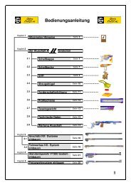
Chapter Content Page<br />
1 General Remarks 2<br />
2 Attaching the Barreled Action 3-4<br />
3 Inserting the Bolt 5<br />
4 Disassembling the Bolt 6-8<br />
5 Front Sight Clamp 8<br />
6 Accessory Rail 9<br />
7 Stock 10-11<br />
8 Cheek Rest Adjustments 12-15<br />
9 Magazine Holder 16-17<br />
10 Magazine 18<br />
11 Trigger Adjustments 19-21<br />
12 Rubber and Aluminum Buttplate 21<br />
13 Front and Rear Sight 22<br />
14 Maintenance and Cleaning 23<br />
15 Servicing the Rifle 24<br />
16 Accessory List 25-30
Dear Rifle Owner<br />
Page 2<br />
1. General Remarks<br />
Congratulations for buying this precision rifle. We are convinced that you will be very<br />
satisfied with this purchase, as most match shooters highly value our rifles because<br />
of their careful construction and great accuracy.<br />
Before using this rifle please read carefully the following eight reminders:<br />
1. Always treat this rifle as loaded. Make sure there is no ammunition in the<br />
chamber. Always carry your rifle with an open bolt and without a magazine, to<br />
indicate it is not loaded.<br />
2. Never point a rifle at anybody (whether it is loaded or not).<br />
3. Before shooting, always make sure that you are using the correct ammunition for<br />
the rifle.<br />
4. Before shooting, always make sure that the barrel is free of any<br />
obstructions.<br />
5. Always keep the safety in either the safe position or fire position (where the red<br />
dot is visible) - never in between. Always keep the safety in the safe position until<br />
you are ready to fire a shot. Make sure that there is nothing in between the target<br />
and the muzzle. Do not touch the trigger when you change the position of the<br />
safety or when you do not intent to fire a shot.<br />
6. All service of your rifle should be performed by an authorized gunsmith, except for<br />
routine maintenance.<br />
7. The proper functioning of the rifle, in particular its accuracy depends on careful<br />
maintenance. Please read the instructions thoroughly.<br />
8. Only a well trained shooter (or a person supervised by a well trained shooter)<br />
should use this rifle.
Page 3<br />
The bedding block 1 and the buffer plate 2 must be thoroughly cleaned before<br />
shaped recoil lug 3 and the rear bedding buffer 4 .<br />
3<br />
1<br />
Bedding block 2 Buffer plate<br />
Wedge shaped recoil lug 4 Rear bedding buffer<br />
We are now ready to insert the trigger plate 6 at an angle of about 30°.<br />
6<br />
2. Attaching the Barreled Action<br />
The stock and barreled action are shipped separately to minimize the possibility of<br />
damage. When assembling the rifle, please proceed as follows:<br />
assembly. The same applies to the matching parts of the barreled action, the wedge<br />
Important: Do not use any cleaning solvents! Just wipe the four surfaces clean with a<br />
dry, lint-free cloth.<br />
Gently insert the barreled action into the stock, but do not insert the action screws<br />
yet.<br />
Now turn the rifle upside down holding the stock and the barreled action together with<br />
your hand (otherwise it will fall apart because the action screws are not inserted yet).<br />
Trigger plate<br />
5<br />
5<br />
5
6<br />
7<br />
Trigger plate<br />
Magazine well<br />
11<br />
Page 4<br />
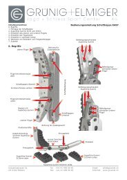
Important: Please make sure that the “fingers” of the trigger plate 9 are slipped<br />
under the trigger guard 8 (else the trigger plate is not held firmly in place).<br />
Insert the action screws. The (short) rear action screw 5 is inserted into the<br />
6<br />
trigger plate , the (long) front action screw is inserted through the accessory rail<br />
underneath the recoil lug. Starting with the front action screw, tighten both action<br />
screws slowly alternating between them. Make sure that your other hand still<br />
holds the barreled action and the stock together until the screws are relatively<br />
tight.<br />
Tighten both screws to 5Nm with the long hex wrench, size 5. How can you<br />
tighten the screws to exactly 5Nm? By holding the hex wrench at the end and<br />
lifting the vertically positioned rifle tightening the screws using its own weight (see<br />
left picture below). The weight of the rifle will tighten the screw to 5Nm. You can<br />
also buy from us a metric torque wrench (#4405) with a 5mm hexagonal insert<br />
(#4407) – consult the accessory list in chapter 16.<br />
Both action screws come with a Dubo plastic washer to prevent loosening. If done<br />
carefully the action screws can be tightened and loosened about 20-30 times<br />
before the plastic washers need to be replaced. When you loosen the screws it is<br />
important that the plastic washers remain attached to the screw heads – they<br />
should be viewed as a single unit that should never be taken apart. If the plastic<br />
washer is worn to the point where it is not malleable it should be replaced because<br />
it cannot fulfill its purpose of securing the screw any longer.<br />
10<br />
5 Nm<br />
long hex wrench 5.0mm<br />
Rear action screw (short)<br />
9<br />
8<br />
Upper projections<br />
of the trigger<br />
guard<br />
„Fingers“ of the<br />
trigger plate must<br />
slip under the trigger<br />
guard<br />
Front action screw (long)<br />
- always tighten first
4<br />
Page 5<br />
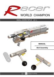
3. Inserting the Bolt<br />
For safety reasons, we deliver the bolt in the un-cocked position. Before inserting the<br />
bolt into the receiver you need to first cock the bolt.<br />
Grip the bolt firmly by the handle. Take the spanner wrench FT 300 3 from the tool<br />
kit and place the matching slot onto the cocking lug. Now cock the lug by moving it<br />
along the cocking cam until it rests firmly in the new, cocked position. You can see<br />
that the bolt is cocked 1<br />
by observing whether the red cocking indicator projects<br />
5mm from the bolt cap.<br />
Insert bolt into the receiver by moving the cocking lug to the bottom. In this position<br />
the bolt handle is positioned at two o’clock (or 60° to the right). The three bolt lugs<br />
can now be inserted into the matching raceways. When inserting the bolt the release<br />
lever 4 automatically clicks into position. Press in on the bolt release lever to<br />
remove the bolt.<br />
2<br />
Cocking lug in uncocked<br />
position<br />
Bolt release lever<br />
3<br />
Cocking cam<br />
1<br />
Cocking lug in cocked<br />
position<br />
Cocking lug in cocked<br />
position; cocking<br />
indicator projects 5mm
Important:<br />
Page 6<br />
4. Disassembling the Bolt<br />
The bolt must first be un-cocked 2 . The procedure is the reverse of the cocking<br />
procedure described in the previous chapter 3. Check the red cocking indicator to<br />
make sure that it is flush with the bolt cap.<br />
Cocking lug in uncocked<br />
position;<br />
cocking indicator is<br />
flush with bolt cap<br />
Position the bolt face on a firm, non-slippery surface. Firmly grip the shaft of the bolt<br />
with one hand 5 . Press the bolt cap down with the other hand 6<br />
and then twist it<br />
90° clockwise (while still pressing down) to disengage the bayonet lug. Slowly<br />
release the compression of the spring to remove the bolt cap.<br />
Step 1:<br />
Press about 5mm<br />
down on the bolt cap<br />
drücken.<br />
6<br />
3<br />
5<br />
5<br />
Step 2:<br />
Turn 90° while<br />
still holding down<br />
the bolt cap<br />
Step 3:<br />
Slowly release the<br />
compression of the<br />
spring.
7<br />
Step 3: Slowly release compression to<br />
remove cocking sleeve<br />
3<br />
Page 7<br />
Remove the firing pin assembly from the bolt cylinder.<br />
Firmly place the spanner wrench <strong>FT300</strong> 3 in a vise making sure that the stripping<br />
hole for the firing pin is easily accessible. Now put the firing pin through the concave<br />
side of the stripping hole. Press on the bolt sleeve with your hand 7<br />
and then twist<br />
it 90° clockwise (while still pressing down) to disengage the bayonet lug. Slowly<br />
release the compression of the spring to remove the cocking sleeve. Now you can<br />
easily remove the spring and slotted washer.<br />
Step 2: Turn cocking sleeve<br />
90° clockwise<br />
Step 1: Move cocking sleeve about<br />
5mm towards the front Firmly placed <strong>FT300</strong><br />
Spanner wrench<br />
Stripping hole<br />
for firing pin<br />
X-ray view of the bolt<br />
Spanner wrench <strong>FT300</strong><br />
Bolt cap<br />
Remove firing pin<br />
assembly from the<br />
bolt cylinder.
Page 8<br />
The reassembly of the bolt is done in reverse. Engage the bayonet lug of the bolt<br />
cap by compressing and turning it counterclockwise until it securely locks into<br />
position. Don’t forget to cock the bolt before inserting it as described in chapter 3.<br />
5. Front Sight Clamp<br />
The barreled action is delivered with the fully assembled and correctly positioned<br />
front sight clamp. You don’t have to disassemble the front sight clamp to transport<br />
the rifle, however if you decide to disassemble the front sight clamp follow these<br />
steps:<br />
Mark the original position with a pencil line on the front sight band and the muzzle.<br />
Mark original<br />
position with a<br />
pencil line<br />
Important: Normal tightening of screws is sufficient. Do not overt-tighten screws.<br />
This can lead to a significant loss of the rifle’s accuracy.<br />
The yellow colored thermo-barrier sleeve 1 can easily be positioned. Just insert<br />
the sleeve into the front sight clamp and turn it until the two little balls snap into<br />
position.<br />
Only remove the thermo-barrier sleeve if it is defective. In case you do have to<br />
remove the thermo-barrier sleeve, make sure not to lose the two little balls and<br />
springs - they are held in position by the sleeve and will fly through the room if not<br />
properly disassembled.<br />
1<br />
The ring of the mirage<br />
band is mounted on the<br />
front sight with a screw<br />
des Kornfusses befestigt.<br />
Thermo-barrier<br />
sleeve<br />
When adjusting the front sight<br />
insert the spanner wrench in the<br />
slit of the clamp and sleeve. The<br />
yellow thermo barrier is thus<br />
moved simultaneously with the<br />
clamp.
Page 9<br />
6. Accessory Rail<br />
The accessory rail holder can be turned 180° to move it 7mm off center.<br />
The rail insert should be<br />
turned 180° at the same<br />
time as the accessory rail<br />
holder to prevent the<br />
numbered scale from being<br />
upside down<br />
Step 2: Unscrew the 4 Phillips screws<br />
from the rail insert holder.<br />
Step 1: Unscrew the 3 Phillips screws of<br />
the rail insert.<br />
The rail insert holder can be<br />
moved 180°<br />
The rail has the same dimensions as any Anschütz-rail. Therefore you can use all<br />
Anschütz accessories.<br />
7mm
Page 10<br />
7. Stock<br />
Important: Always transport your rifle in a hardcover gun case. This is the only<br />
way to properly protect your rifle even when you transport it in a car.<br />
The forearm of the stock is tapered 1 to give the hand more freedom and to<br />
prevent the fingers from being forced apart, especially in the kneeling and prone<br />
position.<br />
1<br />
Tappered forearm<br />
Ventilation slots<br />
Thumb rest 4<br />
3° inclination of<br />
cheek rest<br />
Finger grove<br />
The finger grove 2 guides the index finger to the trigger.<br />
2<br />
Deep cut of the<br />
buttstock<br />
The buttstock is deeply cut at the bottom 3 to prevent the rifle from directly<br />
resting on the chest when shooting in the standing position.<br />
Aluminum<br />
buttplate<br />
The cheek rest is inclined downwards 3 degrees 4 to divert the recoil from the<br />
cheekbone. The cheek rest is also elongated so that shooters who rest their heads<br />
close to the rear sight have an optimal head position. In addition, the cheek rest can<br />
be moved back and forth (see chapter 8).<br />
The prism shaped bedding block 6 is cast directly into the stock and cannot be<br />
removed. Make sure that the surface of the bedding block and the buffer plate are<br />
not damaged.<br />
6<br />
Prism shaped bedding block Buffer plate<br />
3<br />
5<br />
Horizontal<br />
adjustment of<br />
cheek rest
Page 11<br />
You can fine tune your <strong>FT300</strong> by adding extra weights. Remove the aluminum<br />
buttplate 5<br />
and you will find some extra space 7 for weights. If you have trouble<br />
making your own weights out of aluminum, steel, or lead, feel free to contact your<br />
gunsmith or us directly.<br />
8<br />
Space for extra weigts<br />
Extra weights can also be used in the forearm of the stock. Please contact your<br />
gunsmith or us for proper placement of extra weights.<br />
Always treat the stock like a raw egg – it is worth it!<br />
Space for extra weights<br />
7<br />
Space for extra weights<br />
Slot for accessing the hex screw of the cheek rest<br />
adjustment mechanism
4<br />
Page 12<br />
8. Cheek Rest Adjustments<br />
The cheek rest of the base model rifle can be adjusted vertically 1 , laterally 2 ,<br />
and at an angle 3 . The rifle comes with one 5mm spacer 4 . If you are a shooter<br />
who needs to have a high cheek rest, you need to order additional spacers<br />
(maximum 3 altogether) for the proper functioning of the main body 5 . Please<br />
consult the accessory list in chapter 16 for the exact part number.<br />
5mm spacer (maximum 3<br />
spacers possible)<br />
5<br />
Main body<br />
Lateral adjustments<br />
In order to make height adjustments you do not need to take the cheek rest out of the<br />
stock. Simply loosen the middle hex screw 6 at the bottom and then use the long<br />
hex wrench 5.0mm to turn the two screws 7<br />
to move the cheek rest:<br />
Turn clockwise = cheek rest moves down<br />
Turn counter-clockwise = cheek rest moves up<br />
Both screws must be<br />
adjusted the same<br />
length otherwise the<br />
cheek rest is tilted<br />
7<br />
Adjustment with long hex<br />
wrench 5.0mm<br />
Angle adjustments<br />
Vertical adjustments<br />
Cut away view of the<br />
buttstock<br />
Hex screw to tighten cheek rest<br />
with long hex wrench 5.0mm<br />
You can switch from the base model rifle to the match model at any time without<br />
changes to the stock.<br />
6<br />
2<br />
3<br />
1
Page 13<br />
If you opted for the match version, you can adjust the cheek rest almost in any<br />
direction: vertically 8 , laterally 9 , asymmetrical laterally 10 , at angle 1 11 , at<br />
angle 2 12 , and horizontally 13 . If a shooter requires a high cheek rest, you need to<br />
order additional spacers (maximum 3 altogether. Please consult the accessory list in<br />
chapter 16 for the exact part number.<br />
X-ray view of the cheek<br />
rest<br />
Angle 2 adjustment<br />
Angle 1 adjustment<br />
5mm spacer (maximum 3 )<br />
12 11 8<br />
10<br />
Asymetrical<br />
Lateral adjustment<br />
9 13<br />
Cheek adjustment piece<br />
can be turned 180°<br />
Locking plate can be<br />
turned 180°<br />
Horizonal adjustment<br />
Asymetrical 180°<br />
Vertical-adjustment<br />
You can either just turn the cheek adjustment piece 180° or the locking plate 180°<br />
or both at the same time. Do not hesitate to try out what works best for you.<br />
10
14<br />
14<br />
Easy Adjustment of the Cheek rest:<br />
Page 14<br />
Loosen the two hex screws 15 of the locking plate with the long hex wrench 4.0mm<br />
Now you can easily remove the cheek rest from the buttstock.<br />
Hex wrench 4.0mm<br />
One of the height adjustments screws has engraved numbers and a thumb nut for<br />
convenient adjustment.<br />
Numbers of the height<br />
adjustment screw<br />
To move the cheek rest horizontally just loosen the middle screw 16 on the bottom<br />
of the buttstock.<br />
16<br />
Thumb nut<br />
Hex screw for horizonal<br />
adjustment<br />
15<br />
X-ray view of the locking<br />
plate<br />
Hex screws of the<br />
locking plate<br />
Hex wrench 4.0mm<br />
Cut away view of the<br />
buttstock
15<br />
Page 15<br />
Important: To adjust angle 2 12 (see page 13) do not loosen the two screws 15 of<br />
the clamp. Only loosen the middle screw 16 all the way. Completely<br />
remove the cheek rest from the buttstock. Now you can adjust angle 2<br />
by loosening the two hex screws 17 . To see whether the angle is the<br />
one you want, insert the cheek rest into the buttstock. Make further<br />
adjustments if necessary. When you are finished adjusting tighten the<br />
hex screw 16 again.<br />
Hex wrench 4.0mm<br />
16<br />
Locking plate<br />
Why is this necessary ?<br />
The height adjustment screws are guided in the locking plate and thus<br />
do not have to be synchronized.<br />
Locking plate<br />
Hex screw for horizontal<br />
adjustment<br />
Riser block<br />
17<br />
Rail (both sides)<br />
Hex wrench 4.0mm<br />
Angle 2 can be adjusted by<br />
loosening the two hex<br />
screws<br />
The locking plate will stay attached<br />
to the height adjustment screws of<br />
the cheek rest if you do not loosen<br />
the two hex screws (as described in<br />
the text)<br />
Hex screws for angle 2<br />
adjustment<br />
Make sure that when you assemble<br />
the riser block and the locking plate<br />
that the rails of the riser block are<br />
locked in the nuts of the locking plate<br />
17<br />
12<br />
Hex wrench 4.0mm
Page 16<br />
9. Magazine Holder<br />
The magazine holder is attached with three screws to the magazine well and is<br />
constructed to be maintenance free. If the magazine holder needs to be detached,<br />
please contact a gunsmith or us directly.<br />
What should you inspect from time to time?<br />
Make sure the three screws are tight. As illustrated below, you can do this with the<br />
assembled as well as with the disassembled rifle.<br />
Hex screw M4x12<br />
long<br />
Hex wrench long 3.0mm<br />
Magazine ejector spring<br />
Hex screw M4x10<br />
short<br />
Magazine release button<br />
You should be able to insert the magazine without resistance. The magazine ejector<br />
has to click into place without any effort. When the magazine release button 1 is<br />
pressed the magazine must be released instantly and without resistance.<br />
1
The magazine ejector spring must<br />
be placed correctly behind the two<br />
lips<br />
Page 17<br />
Rifles without the magazine have a magazine well without the magazine holder<br />
mechanism. In addition, the magazine well lacks the finger guide for the magazine<br />
release button 3 . The magazine well is closed with a cover 4 which is held into<br />
place with six screws 5 .<br />
Finger guide<br />
5<br />
Lips<br />
Screws<br />
4<br />
3<br />
Without finger guide<br />
Cover of magazine well
1<br />
Laser-engraved<br />
cartridge<br />
3<br />
Follower<br />
Page 18<br />
10. Magazine<br />
Cartridge<br />
count indicator<br />
Arrow<br />
Laser-engraved caliber<br />
Magazine holds<br />
10 cartridges<br />
Fill magazine from above<br />
(also possible with clip)<br />
The magazine is also maintenance free. Never take the magazine apart. If there are<br />
problems contact an authorized dealer or us. If you have trouble discerning the front<br />
and rear of the magazine look at the laser-engraved cartridge on the side of the<br />
magazine 1 or the arrow 2 on the magazine floor plate.<br />
The follower can be tested by pressing it with two fingers inside the magazine. The<br />
follower must operate without getting stuck. The rifle can be used in single shot mode<br />
by inserting the empty magazine. You can set the cartridge on top of the follower 3<br />
and then close the bolt.<br />
2
Adjusting the Trigger<br />
Page 19<br />
11. Trigger Adjustments<br />
The UIT-Standard-Rifles have a 1.5 kg trigger as delivered from the factory, with the<br />
first stage set to about 1,000 grams. You can adjust the total pull weight, the pull of<br />
the first stage, and the travel of the first stage.<br />
Adjusting the Trigger Blade (UIT-Standard)<br />
The trigger blade can be adjusted horizontally along the trigger bar.<br />
Adjusting the Travel of the First Stage<br />
Turning the adjustment screw 3 clockwise will reduce the travel; turning it<br />
counterclockwise will increase the travel.
Total Trigger Pull<br />
Adjusting the Sear Engagement<br />
Page 20<br />
Turning the adjustment screw 2 clockwise will increase the sear engagement.<br />
Turning it counter clockwise will decrease it.<br />
If the trigger drags, turn adjustment screw 2 counter clockwise in small increments<br />
until the drag disappears. While performing this adjustment the trigger pull will<br />
decrease at the same time. Thus you have to compensate for this with adjustment<br />
screw 4 .<br />
If there is no (or too little) transition to the second stage, turn adjustment screw<br />
clockwise incrementally until achieving the desired setting. While performing this<br />
adjustment the trigger pull will increase at the same time. Thus you have to<br />
compensate for this with adjustment screw 4 .<br />
Adjusting the Trigger Pull without Altering the Pull of the First Stage<br />
The minimum trigger pull weight, required by UIT, is 1,5 kg. Any adjustment is made<br />
with screw 4 . Turning the screw clockwise will increase the trigger pull weight<br />
turning the screw counter-clockwise will decrease the trigger pull. Each adjustment<br />
requires a resetting of the adjustment screw 2 in the same direction.<br />
See (above): Adjusting the Sear Engagement<br />
Adjusting the First Stage Pull<br />
Each adjustment of the first stage pull automatically changes the total pull weight<br />
(1.5 kg) of the trigger (see diagrams below). Turning adjustment screw 1<br />
clockwise will increase the first stage pull; turning the screw counter clockwise will<br />
decrease the first stage pull. If the total trigger pull weight becomes less than the<br />
required 1.5 kg, you need to re-adjust the total trigger pull with adjustment screw 4 .<br />
Original trigger setting Increasing the first stage pull Deacreasing the first stage pull<br />
2000g 2000g 2000g<br />
1500g Trigger breaks<br />
1500g<br />
Trigger breaks<br />
1500g<br />
1000g Transition to<br />
second stage<br />
1000g<br />
Transition to<br />
second stage<br />
1000g<br />
500g 500g 500g<br />
0g 0g 0g<br />
1mm 2mm 3mm 1mm 2mm 3mm 1mm 2mm 3mm<br />
Travel Travel Travel<br />
See (above): Adjusting the Trigger Pull Without Altering the Pull of the First Stage<br />
2<br />
Trigger<br />
breaks<br />
Transition to<br />
second stage
Page 21<br />
If you made significant adjustments to the trigger we recommend asking a gunsmith<br />
to check the total trigger pull weight of 1.5 kg only on the barreled action (see<br />
illustration below). This will keep you out of trouble at competition checks.<br />
Aluminium buttplate<br />
(yellow)<br />
Barreled action<br />
12. Rubber and Aluminum Buttplate<br />
To lengthen the rubber buttplate you<br />
can use our 8mm aluminum spacers<br />
(see accessories at the end). If you<br />
insert more than three spacers you<br />
need to purchase longer screws from<br />
an authorized dealer or directly from<br />
us.<br />
To lengthen the aluminum buttplate<br />
you can use our 8mm spacers (see<br />
accessories at the end). If you insert<br />
more than three aluminum spacers you<br />
need to purchase longer screws from<br />
an authorized dealer or directly from us.<br />
15mm 15mm<br />
According to the new UIT rules you can move<br />
the buttplate only 15mm in a line straight from<br />
the center (regular dashed line)<br />
Important: The buttplate cannot be canted<br />
(see bold dashed line).
Page 22<br />
13. Front and Rear Sight<br />
The rifle includes an Anschütz rear sight (model 7002). Please read the original<br />
Anschütz instructions for this rear sight. We add some useful information below:<br />
Both the elevation and windage adjustment at 300 meter is 1.5cm per click (for the<br />
10 click rear sight) and 0.75cm per click (for the 20 click rear sight). We only deliver<br />
the 20 click rear sight upon explicit request.<br />
Never change the rear sight angel during competition because it can change your<br />
zeros. Thus, only change the rear sight angle if you are allowed sighters<br />
For both front and rear sight you can use all accessories of <strong>Grünig</strong> & <strong>Elmiger</strong> <strong>AG</strong>,<br />
Centra, AHG-Anschütz, J.G. Anschütz and Gehmann.<br />
Anschütz rear sight<br />
Anschütz front sight
Page 23<br />
14. Maintenance and Cleaning<br />
Wipe the bolt from time to time with a clean, lint-free cloth. Afterwards apply some<br />
gun oil sparingly.<br />
We recommend cleaning the barrel carefully as follows after each shooting:<br />
Apply solvent or gun oil to the barrel immediately after shooting to remove<br />
powder residue (the barrel should still be warm).<br />
Clean the barrel and chamber from the breach end with a high grade cleaning<br />
rod and brass brush. The brush must be completely soaked in solvent and when<br />
it clears the muzzle unscrew it before withdrawing the cleaning rod, in order not<br />
to damage the muzzle. Repeat this procedure 2-3 times and then clean with VG<br />
640 bore swabs or cleaning patches until all residue is removed.<br />
Lightly oil the bore and chamber.<br />
Don’t forget to wipe the bore clean with some dry patches before the next shooting!<br />
After shooting 200-300 rounds, we recommend that you remove fouling with a<br />
special bore cleaning solvent such as Robla Solo. Please carefully follow the<br />
manufacture’s instructions.<br />
All external parts, such as the bolt and the exterior of the barrel should be wiped off<br />
with a lightly oiled cotton cloth. We especially recommend the environmentally<br />
friendly gun oil manufactured by Ballistol<br />
For more information on the gun oil Ballistol consult their website:<br />
www.klever-ballistol.de
Page 24<br />
15. Servicing the Rifle<br />
The standard rifle <strong>FT300</strong> is made with the most modern materials and techniques.<br />
However, in every rifle there is normal wear and tear, in particular in the barrel. We<br />
therefore recommend, that you send your rifle once a year to your gunsmith or us for<br />
a check up (usually the best time is Winter).<br />
During the check-up we inspect and measure the following:<br />
- Caliber of the barrel<br />
- Muzzle<br />
- Chamber<br />
- Bore (using a bore scope)<br />
- Trigger<br />
- Bolt and firing pin<br />
- Stock<br />
- Test shooting<br />
In addition all other parts are inspected visually.<br />
We offer you this service once a year for CHF 85.- This offer is valid until the year<br />
2003 (transportation cost are not included). Please call us to make reservations for<br />
this service to make sure you have your rifle back as soon as possible.<br />
We also recommend that you keep track of the number of shots fired. This makes it<br />
easier for us to better judge the barrel and make appropriate recommendations.
Front sight<br />
Accessories<br />
Part-No. 16.3120<br />
Part -No. 16.3145<br />
Part -No. 16.3245<br />
Part -No. 16.3170<br />
Part -No. 16.3180<br />
Part-No. 16.3074<br />
Part-No. 16.0430<br />
Page 25<br />
16. Accessory List<br />
Iris aperture 120<br />
2.8 – 4.8mm<br />
clear glass<br />
Iris aperture GE 145<br />
2.8 – 4.8mm<br />
changeable from cross<br />
hair to horizontal hair<br />
Varioswing GE 245<br />
2.5 – 5.0mm<br />
changeable from cross<br />
hair to horizontal hair<br />
Duo iris aperture<br />
2.8 – 4.8mm / 6.4 - 9.0<br />
changeable from cross<br />
hair to horizontal hair<br />
Duo-Iris aperture front<br />
sight clear glass<br />
2.8 – 4.8mm / 6.4 - 9.0<br />
Set of colored plastic<br />
rings (blue / red / silver /<br />
yellow / green)<br />
Anschütz front sight<br />
inserts including post<br />
sights 16.0440
Rear sight<br />
accessories<br />
Part-No. 16.3190<br />
Part -No. 16.3191<br />
Part -No. 16.3011<br />
Part-No. 16.3030<br />
Part -No. 16.3044<br />
Part -No. 16.3055<br />
Part -No. 16.3074<br />
Thin version<br />
Part -No. 16.3075<br />
Thick version<br />
Part -No. 16.0120<br />
Page 26<br />
Large, translucent<br />
eyeshield<br />
Small, translucent<br />
eyeshield<br />
GE 11 Iris aperture<br />
0.5 –3.0 mm<br />
GE 33 Iris aperture<br />
5-color filter<br />
0.5 –3.0 mm<br />
GE 44 Iris aperture<br />
5-color plus +<br />
polarization filter<br />
0.5 –3.0 mm<br />
GE 55 Iris aperture<br />
Polarization filter<br />
0.8 –3.0 mm<br />
Set of colored plastic<br />
rings (blue / red / silver /<br />
yellow / green)<br />
thin and thick version<br />
6720 – U1 Rubber<br />
eyeshade
Accessory Rail<br />
Part -No. 16.0960<br />
Part -No. 16.0860<br />
Part -No. 16.0845<br />
Part -No. 16.0850<br />
Part -No. 16.0852<br />
Part -No. 16.3300<br />
Part -No. 16.6020 /<br />
16.6030 Right hand<br />
Part -No. 16.6021 /<br />
16.6031 Left hand<br />
Page 27<br />
Bipod 4770 (useful to<br />
set down the rifle for rest<br />
or cleaning)<br />
Handstop with sling<br />
swivel 6225<br />
Handstop with sling<br />
swivel 4734 /1 ø32 mm<br />
Handstop with sling<br />
swivel 4751<br />
Handstop with sling<br />
swivel 4752<br />
Centra handstop with<br />
sling swivel<br />
UIT sling (right and left<br />
hand)
Miscellaneous<br />
Accessories<br />
Part -No. 16.0660<br />
Part -No. 28.4580<br />
For one rifle<br />
Part -No. 28.4610<br />
For two rifles<br />
Part-No. 28.4640<br />
Extra large model<br />
Part -No. 16.2188<br />
Page 28<br />
4405 Torque wrench<br />
Gun case for one or<br />
for two rifles (including<br />
extra large model)<br />
Universal wrenches<br />
Gun safes<br />
Security level A and<br />
Security level B<br />
(separated)
<strong>FT300</strong> Accessories<br />
Part -No. 16.0730<br />
Part -No. 407-04-013<br />
Part -No. 205-01-010<br />
30mm silver<br />
Part -No. 205-01-015<br />
30mm yellow<br />
Part -No. 205-01-013<br />
25mm silver<br />
Part -No. 205-01-014<br />
25mm yellow<br />
Part -No. 407-05-004<br />
Article-No. 407-06-018<br />
Article-No. 407-05-002<br />
Article-No. 407-06-021<br />
Page 29<br />
8mm spacer only for<br />
the rubber but plate<br />
8mm washers only for<br />
aluminum but plate<br />
Aluminum bolt handle<br />
knob 30mm (silver or<br />
yellow)<br />
Aluminum bolt handle<br />
knob 25mm (silver or<br />
yellow)<br />
5mm cheek rest spacer<br />
for base model (see<br />
chapter on cheek rest<br />
adjustment)<br />
5mm cheek rest spacer<br />
for match model (see<br />
chapter on cheek rest<br />
adjustment)<br />
Complete cheekrest<br />
adjustment mechanism<br />
for match model<br />
Complete cheekrest<br />
adjustment mechanism<br />
for base model
Cleaning set<br />
Page 30<br />
VFG bore swabs for different calibers<br />
VFG cleaning rods (one piece or<br />
multiple pieces)