Ultrasonic Spray Nozzle Systems Sono-Tek Corporation
Ultrasonic Spray Nozzle Systems Sono-Tek Corporation
Ultrasonic Spray Nozzle Systems Sono-Tek Corporation

Create successful ePaper yourself
Turn your PDF publications into a flip-book with our unique Google optimized e-Paper software.
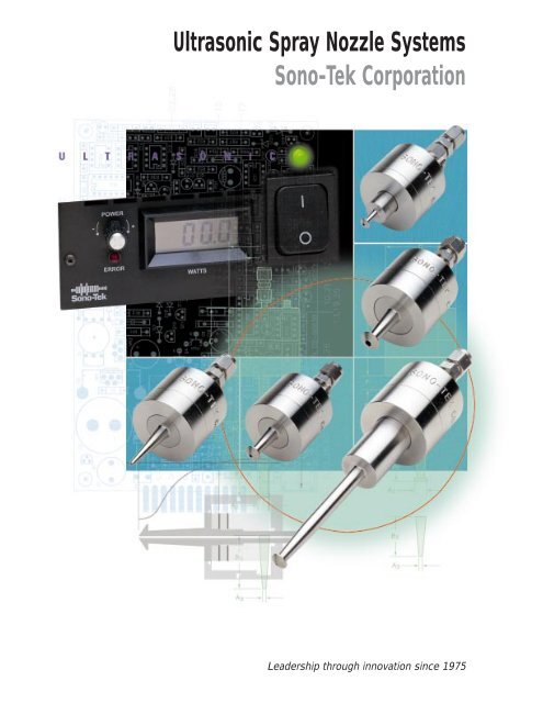
<strong>Ultrasonic</strong> <strong>Spray</strong> <strong>Nozzle</strong> <strong>Systems</strong><br />
<strong>Sono</strong>-<strong>Tek</strong> <strong>Corporation</strong><br />
Leadership through innovation since 1975
2<br />
When<br />
Precision<br />
Counts…<br />
<strong>Ultrasonic</strong> spray nozzle systems are<br />
replacing pressure nozzles in a wide<br />
range of industrial and R&D<br />
applications. Concerns over the<br />
environment and unacceptable quantities<br />
of waste have caused scientists,<br />
engineers and designers to adopt<br />
ultrasonic spraying systems as a<br />
technology that is more precise, more<br />
controllable, and more environmentally<br />
friendly.<br />
<strong>Sono</strong>-<strong>Tek</strong> ultrasonic nozzles, with<br />
their characteristic soft spray, dramatically<br />
reduce overspray, which saves<br />
money and reduces atmospheric<br />
contamination. They also open up a<br />
broad range of new application<br />
possibilities. They are ideal, for<br />
example, when extremely low flow<br />
rates are required. And since they<br />
will not clog or wear out, they help<br />
reduce downtime in critical manufacturing<br />
processes.<br />
For substrate coatings, moisturizing,<br />
spray drying, web coating, fine-line<br />
spraying, and many other industrial<br />
and R&D applications, <strong>Sono</strong>-<strong>Tek</strong><br />
ultrasonic nozzles yield results far<br />
superior to other techniques.<br />
<strong>Sono</strong>-<strong>Tek</strong> <strong>Ultrasonic</strong><br />
<strong>Nozzle</strong>s reduce:<br />
• Material consumption by up to 80%<br />
• Wasteful overspray and atmospheric<br />
contamination<br />
• Waste disposal<br />
• Servicing and downtime<br />
Versatile, Reliable, Consistent<br />
• <strong>Spray</strong> patterns are easily shaped for<br />
precise coating applications<br />
• Highly controllable spray produces<br />
reliable, consistent results<br />
• Non-clogging<br />
• No moving parts to wear out<br />
• Corrosion-resistant titanium and<br />
stainless steel construction<br />
• Ultra-low flow rate capabilities,<br />
intermittent or continuous<br />
Serving an Entire<br />
Spectrum of Industry<br />
and R&D Needs<br />
For any application requiring the precise,<br />
controllable spray application of a liquid,<br />
<strong>Sono</strong>-<strong>Tek</strong> ultrasonic nozzles offer reliable,<br />
repeatable performance. Typical applications<br />
include:<br />
Semiconductor/Electronics<br />
• Dispensing photolithographic chemicals<br />
onto semiconductor wafers and flat<br />
panel displays<br />
• Precision fluxing on SMT circuit<br />
boards and components using our<br />
Accu•Mist system<br />
• Fluxing through-hole circuit boards<br />
using our <strong>Sono</strong>Flux 9500 <strong>Spray</strong> Fluxer<br />
• Lubricating computer hard disks<br />
• Microsphere deposition on flat panel<br />
displays<br />
• Superconductor substrate coatings<br />
Medical/Biomedical<br />
• Coatings for blood-collection tubes<br />
• Microencapsulation of pharmaceuticals<br />
• Pharmaceutical spray drying<br />
• Coatings for diagnostic test kits<br />
• Protein, enzyme and reagent coatings<br />
General/Industrial<br />
• Fragrance, flavor, and oil coatings<br />
• Ceramic spray drying<br />
• Slurry/suspension atomization<br />
• Solvent and adhesive bonding<br />
• Chemical reaction chambers<br />
Web Coatings<br />
• Float glass, paper, and textiles
<strong>Ultrasonic</strong> Atomization<br />
with <strong>Sono</strong>-<strong>Tek</strong> <strong>Ultrasonic</strong><br />
<strong>Spray</strong> <strong>Nozzle</strong>s<br />
The Process<br />
<strong>Ultrasonic</strong> nozzles employ high-frequency<br />
sound waves to produce atomization. Discshaped<br />
ceramic piezoelectric transducers<br />
receive high frequency electrical energy<br />
from the <strong>Sono</strong>-<strong>Tek</strong> Broadband <strong>Ultrasonic</strong><br />
Generator, described on page 9, and convert<br />
that energy into vibratory mechanical<br />
motion at the same frequency. The transducers<br />
are coupled to two titanium cylinders<br />
that amplify the motion.<br />
The excitation created by the transducers<br />
produces standing waves along the length<br />
of the nozzle, the amplitude of which is<br />
maximized at the atomizing surface, located<br />
at the end of the small diameter portion<br />
of the nozzle. The small diagram below<br />
shows how the amplitude varies along the<br />
axis. Both ends of the nozzle are antinodes,<br />
planes of maximum amplitude. A<br />
node, where the amplitude is zero, is located<br />
at the interface between the transducers.<br />
The step transition from the large to<br />
the small diameter of the front horn provides<br />
the required amplification at the<br />
atomizing surface.<br />
Since both ends are anti-nodes, the nozzle’s<br />
length must be a half-wavelength or a<br />
multiple of a half-wavelength. Wavelength<br />
is dependent upon operating frequency,<br />
so nozzle dimensions are governed<br />
by frequency. In general, high-frequency<br />
nozzles are smaller, create smaller drops,<br />
and have a lower flow capacity than nozzles<br />
that operate at lower frequencies (see<br />
Flow Rate Capacities table on page 7).<br />
Construction<br />
The nozzle body is fabricated from titanium<br />
because of its outstanding acoustical<br />
properties, high tensile strength, and<br />
excellent corrosion resistance. The protective<br />
housing is fabricated from 316<br />
stainless steel. Liquid is introduced onto<br />
B<br />
R<br />
A<br />
O<br />
T<br />
I<br />
U<br />
D<br />
C<br />
A<br />
R<br />
I<br />
S<br />
C<br />
S<br />
the atomizing surface through a large,<br />
non-clogging feed channel running the<br />
length of the nozzle. Liquid emerging onto<br />
the atomizing surface absorbs the vibrational<br />
energy, causing it to atomize.<br />
Energy Control<br />
The vibrational amplitude must be carefully<br />
controlled. Below the so-called critical<br />
amplitude, there is insufficient energy<br />
Atomized Liquid is generated<br />
as a soft, low velocity spray<br />
resulting in minimal overspray.<br />
Atomizing Surface<br />
Anti-Node<br />
E<br />
M<br />
B<br />
Front Housing<br />
Titanium Amplifying<br />
Section (Front Horn)<br />
Node<br />
L<br />
Y<br />
O-Ring Seal<br />
Anti-Node<br />
Maximum<br />
Vibrational<br />
Amplitude<br />
to produce atomization. If the amplitude is<br />
too high, the liquid is literally ripped<br />
apart, and large “chunks” of fluid are ejected.<br />
Only within a narrow band of input<br />
power is the amplitude ideal for producing<br />
the nozzle’s characteristic fine, low-velocity<br />
spray.<br />
The level of input energy is what distin-<br />
O<br />
T<br />
A<br />
R<br />
O<br />
B<br />
A<br />
R<br />
L<br />
Y<br />
A<br />
guishes ultrasonic nozzles from other ultrasonic<br />
devices such as welders, emulsifiers,<br />
and ultrasonic cleaners. Those devices rely<br />
on input power on the order of hundreds<br />
to thousands of watts. For ultrasonic atomization,<br />
power levels are generally from<br />
1 to 15 watts.<br />
Flow Rates<br />
Since the atomization mechanism relies<br />
Titanium Rear Horn<br />
Active Electrode<br />
Ground Electrode Rear Housing<br />
Piezoelectric Transducers<br />
N<br />
D<br />
R<br />
&<br />
D<br />
Ground Lug<br />
Liquid Feed Channel<br />
O-Ring Seal<br />
O-Ring Seal Electrical Connector to the<br />
Broadband <strong>Ultrasonic</strong> Generator<br />
only on liquid being introduced onto the<br />
atomizing surface, and not pressure, the<br />
rate at which a liquid is atomized depends<br />
solely on the rate at which it is delivered<br />
to the surface. Therefore, every ultrasonic<br />
nozzle has an inherently wide flow rate<br />
range. In theory, the “turn down” ratio<br />
(ratio of maximum to minimum possible<br />
flow rate) is infinite. In practice, this ratio<br />
is limited to approximately 5:1.<br />
3
4<br />
<strong>Spray</strong> Patterns<br />
The illustration on the left in the diagram<br />
below indicates a cone-shaped spray pattern<br />
resulting from the conically shaped<br />
atomizing surface. Typically, spray envelope<br />
diameters from 2-3 inches can be<br />
achieved.<br />
The center illustration is characteristic of<br />
<strong>Sono</strong>-<strong>Tek</strong> Micro<strong>Spray</strong> nozzles. For this<br />
type of nozzle, the orifice size ranges from<br />
0.015-0.040 inches. It is usually recommended<br />
for use in applications where flow<br />
rates are very low and narrow spray patterns<br />
are needed.<br />
The illustration on the right depicts a<br />
cylindrical spray shape used in applications<br />
where the flow rate can be relatively<br />
high, but where the lateral extent of the<br />
spray pattern must be limited.<br />
Conical Micro<strong>Spray</strong> Flat<br />
<strong>Nozzle</strong> Specifications<br />
The following product descriptions provide<br />
basic information about standard<br />
<strong>Sono</strong>-<strong>Tek</strong> nozzles. Other configurations<br />
are available to accommodate specific<br />
requirements.<br />
All maximum flow rates quoted are<br />
approximate and have been measured<br />
using water at room temperature and standard<br />
atmospheric pressure. Refer to the<br />
Flow Rate Capacities table on page 7 for<br />
further details about recommended configurations<br />
for specific flow rates.<br />
Specifications<br />
C<br />
I<br />
D<br />
E<br />
M<br />
A<br />
L<br />
D<br />
E<br />
Materials<br />
V<br />
I<br />
C<br />
E<br />
Lead zirconate-titanate transducers<br />
Titanium alloy body (Ti-6Al-4V)<br />
316 stainless steel housing<br />
Kalrez ® and Viton ® o-rings<br />
Stainless steel SMA electrical connector<br />
S<br />
Liquid Inlet<br />
316 stainless steel Swagelok ®<br />
fitting (standard sizes for 1/4", 1/8",<br />
and 1/16" tubing)<br />
Operating Temperature Range<br />
- 20°C to 150°C (-4°F to 302°F)<br />
External Pressure Range<br />
Vacuum to 100 psi<br />
Operating Maximum Median<br />
Frequency Flow Rate* Drop Dia Weight<br />
Model (kHz) (gph or ml/s) (microns) (g)<br />
8700-25 25 3.3 70 468<br />
8700-35 35 6.0 49 773<br />
8700-48 48 2.4 38 309<br />
8700-48H 48 1.2 38 258<br />
8700-60 60 1.2 31 195<br />
8600-6015 60 0.3 31 251<br />
8700-120 120 0.4 18 196<br />
*Based on maximum orifice diameters for each model. Micro<strong>Spray</strong> series nozzles are limited to 0.3 gph(ml/s) max. flow rate.
<strong>Nozzle</strong> Styles<br />
C<br />
B1<br />
Figure 1 Figure 2 Figure 3<br />
A1<br />
A2<br />
B2<br />
B3<br />
A3<br />
D<br />
E<br />
Dimensions for Standard <strong>Nozzle</strong>s inches(mm)<br />
Other configurations are available.<br />
Model Fig A1 B1 A2 B2 A3 B3 C D E F<br />
8700-25 1 0.46 2.25 0.35 2.08 0.12 2.76 2.5 1.69 1.00 —<br />
(12) (57) (9) (53) (3) (70) (63) (43) (25)<br />
8700-35 1 0.65 1.46 — — — — 2.1 2.44 1.50 —<br />
(17) (37) (53) (62) (38)<br />
8700-48 1 0.46 1.06 0.46 0.86 0.12 1.47 1.5 1.69 1.00 —<br />
(12) (27) (12) (22) (3) (37) (38) (43) (25)<br />
8700-48H 1 0.46 0.89 0.46 0.61 0.09 1.40 1.5 1.69 0.75 —<br />
(12) (23) (12) (15) (2) (36) (38) (43) (19)<br />
8700-60 1 0.35 0.83 0.35 0.75 0.09 1.13 1.3 1.44 0.75 —<br />
(9) (21) (9) (19) (2) (29) (33) (37) (19)<br />
8600-6015 3 0.25 2.51 0.25 2.43 0.09 2.79 1.4 1.44 0.75 1.17<br />
(6) (64) (6) (62) (2) (71) (36) (37) (19) (30)<br />
8700-120 2 0.23 0.44 0.23 0.40 0.09 0.56 1.0 1.44 0.50 0.34<br />
(6) (11) (6) (10) (2) (14) (25) (37) (13) (9)<br />
C<br />
F<br />
B1<br />
A1<br />
A2<br />
B2<br />
B3<br />
A3<br />
D<br />
E<br />
C<br />
F<br />
B1<br />
A1<br />
A2<br />
B2<br />
B3<br />
A3<br />
D<br />
E
Drop Size Distribution<br />
6 In an ultrasonically produced spray, drop one-half of the number of drops in the<br />
size is governed by the frequency at which spray have diameters larger than this value<br />
the nozzle vibrates, and by the surface ten- while the other half have diameters smallsion<br />
and density of the liquid being atomer than this value.<br />
ized. Frequency is the predominant factor.<br />
Median drop size is inversely proportional<br />
to frequency to the 2/3 power. The higher<br />
the frequency, the smaller the median<br />
drop size.<br />
The number mean and weight mean diameters<br />
are average diameters. The number<br />
mean diameter is obtained by adding<br />
together the diameter of each drop in a<br />
spray sample and dividing that sum by the<br />
Typically, the drop-size distribution from number of drops in the sample. The<br />
ultrasonic nozzles follows a log-normal weight mean diameter is obtained by<br />
curve, which has the familiar bell shape, adding together the volume of each drop<br />
but on a logarithmic scale. The chart in a spray sample (volume is proportional<br />
below shows this distribution for water on to diameter cubed), taking the cube root<br />
a cumulative basis at various frequencies. of this sum, and finally dividing by the<br />
Several parameters characterize the mean<br />
and median drop size of a particular distribution.<br />
The number median diameter<br />
defines the 50% point in drop size; that is,<br />
number of drops. The Sauter mean diameter<br />
is a parameter used primarily in combustion<br />
applications. It measures the effective<br />
ratio of drop volume to surface area.<br />
Percent of drops below given diameter<br />
99.99<br />
99.9<br />
99.5<br />
99<br />
98<br />
95<br />
90<br />
80<br />
70<br />
60<br />
50<br />
40<br />
30<br />
20<br />
10<br />
5<br />
2<br />
1<br />
0.5<br />
0.1<br />
120<br />
<strong>Nozzle</strong> Frequency (kHz)<br />
60 48<br />
35<br />
25<br />
0.01<br />
2 4 6 8 10 20 40 60 80 100 200<br />
Drop diameter (microns)<br />
Sauter mean dia.<br />
Weight mean dia.<br />
Number mean dia.<br />
Number median dia.<br />
NOTE:<br />
Data compiled for<br />
water. Other<br />
materials will give<br />
different results.<br />
<strong>Spray</strong> Velocity and Flow<br />
Rate Range Capabilities<br />
<strong>Sono</strong>-<strong>Tek</strong> ultrasonic nozzles produce a<br />
soft, low-velocity spray that eliminates the<br />
overspray typically associated with pressure<br />
nozzles. <strong>Spray</strong> velocities are in the<br />
range 0.7-1.2 feet per second, compared to<br />
35 - 70 feet per second for pressure nozzles.<br />
The unpressurized nature of ultrasonic<br />
atomization allows <strong>Sono</strong>-<strong>Tek</strong> to offer nozzles<br />
over a wide spectrum of flow rate<br />
ranges. For example, our Micro<strong>Spray</strong><br />
series of nozzles can handle flow rates from<br />
μl/m to approximately 0.3 gph (0.3 ml/s),<br />
depending on orifice size. Our highest<br />
capacity nozzle is rated at 6 gph (6 ml/s).
Flow Rate Capacities<br />
The flow rate range is governed by four<br />
factors: orifice size, atomizing surface area,<br />
frequency, and liquid characteristics.<br />
Orifice size plays a principal role in determining<br />
both maximum and minimum<br />
flow rates. Maximum flow rate is related to<br />
the velocity of the liquid stream as it<br />
emerges onto the atomizing surface. The<br />
atomization process relies on the liquid<br />
spreading out onto this surface. At low<br />
stream velocity, surface forces are sufficiently<br />
strong to “attract” the liquid, and<br />
cause it to cling to the surface. As the<br />
velocity of the stream increases, a velocity<br />
is reached where the stream becomes<br />
totally detached from the surface, preventing<br />
atomization.<br />
In theory, there is no lower limit to flow<br />
rate since the process is independent of<br />
pressure. However, in practical terms, a<br />
lower limit does exist. As the flow is<br />
reduced, a point is reached where the<br />
velocity becomes so low that the liquid<br />
emerges onto the atomizing surface haphazardly,<br />
causing the atomization pattern<br />
to become distorted. Typically, the minimum<br />
velocity of the liquid stream from an<br />
orifice of a given size is about 20% of the<br />
maximum velocity.<br />
S<br />
C<br />
I<br />
M<br />
E<br />
O<br />
N<br />
D<br />
U<br />
C<br />
T<br />
O<br />
R<br />
S<br />
The amount of atomizing surface area<br />
available is another factor influencing<br />
maximum flow rate. There is a limit as to<br />
how much liquid an atomizing surface can<br />
support and still sustain the film that is<br />
required to produce atomization. If the<br />
quantity “dumped” onto the surface<br />
becomes too great, it overwhelms the<br />
capability of the surface to sustain the liquid<br />
film.<br />
The maximum flow rate depends not only<br />
on the amount of surface area available,<br />
but also on a nozzle’s operating frequency.<br />
As a result of the dynamics of the process,<br />
lower frequency nozzles can support<br />
Flow Rate Capacities for Water (gph or ml/s)<br />
A<br />
E<br />
R<br />
O<br />
S<br />
P<br />
A<br />
C<br />
E<br />
greater flow rates than higher frequency<br />
nozzles with the same atomizing surface<br />
area.<br />
Finally, the nature of the liquid has a significant<br />
effect on maximum flow rate.<br />
This factor is discussed in the section on<br />
Liquid Compatibility on page 8.<br />
In every instance, one of these factors will<br />
set the maximum flow rate. The table<br />
below lists, for each available frequency<br />
classification, the maximum flow rates of<br />
water for typical combinations of atomizing<br />
surface diameters and orifice sizes.<br />
Maximum flow rates for other liquids may<br />
vary significantly from these values.<br />
Micro<strong>Spray</strong> Series Standard Series<br />
Orifice Size (in) Orifice Size (in)<br />
Freq (kHz) Tip Dia. (in) 0.015 0.030 0.040 0.052 0.067 0.086 0.100 0.141 0.250<br />
25 0.090 0.04 0.15<br />
0.120 0.04 0.15 0.25<br />
0.350 0.04 0.15 0.30 0.45 0.8 1.2 1.7 2.0<br />
0.460 0.04 0.15 0.30 0.45 0.8 1.2 1.7 3.3<br />
0.500 0.04 0.15 0.30 0.45 0.8 1.2 1.7 3.3<br />
35 0.650 6.0<br />
48 0.090 0.04 0.08<br />
0.120 0.04 0.15 0.15<br />
0.400 0.04 0.15 0.30 0.45 0.8 1.2 1.7 1.8<br />
0.460 0.04 0.15 0.30 0.45 0.8 1.2 1.7 2.4<br />
0.500 0.04 0.15 0.30 0.45 0.8 1.2 1.7 2.9<br />
60 0.090 0.04 0.07<br />
0.120 0.04 0.15 0.15<br />
0.300 0.04 0.15 0.30 0.45 0.8 0.9 0.9<br />
0.350 0.04 0.15 0.30 0.45 0.8 1.2 1.2<br />
0.460 0.04 0.15 0.30 0.45 0.8 1.2 1.7<br />
120 0.090 0.04 0.05<br />
0.120 0.04 0.08 0.08<br />
0.230 0.04 0.15 0.30 0.35<br />
7
Liquid Compatibility<br />
H<br />
M<br />
R<br />
A<br />
P<br />
A<br />
C<br />
E<br />
U<br />
T<br />
I<br />
C<br />
A<br />
L<br />
<strong>Sono</strong>-<strong>Tek</strong> Liquid Delivery<br />
<strong>Systems</strong> Ensure Optimum<br />
<strong>Nozzle</strong> Performance<br />
8 Several factors affect the ability of a liquid For pure liquids, the only factor limiting Since a liquid delivery system is required<br />
to be atomized. These include viscosity, atomizability is viscosity. In general, the for every spray application, it is important<br />
solids content, miscibility of components, upper limit of viscosity is on the order of to specify a system that is optimized for<br />
and the specific dynamic behavior of the 50 cps.<br />
performance with <strong>Sono</strong>-<strong>Tek</strong> nozzles. We<br />
liquid. There are no hard-and-fast rules<br />
governing a liquid’s atomizability using<br />
ultrasonics. Some liquids that seem easy to<br />
atomize at first can prove difficult, while<br />
others that seem impossible actually perform<br />
well.<br />
There are, however, guidelines that offer a<br />
good indication of the probability for success.<br />
Liquids can be categorized as follows:<br />
• Pure, single component liquids (water,<br />
alcohol, bromine, etc.)<br />
• True solutions (salt water, polymer<br />
solutions, etc.)<br />
True solutions, for the most part, behave<br />
the same as pure liquids, except when the<br />
solution contains very long-chained polymer<br />
molecules. In that case, the polymer<br />
molecules can interfere with the atomization<br />
process because of their length. Such<br />
molecules will inhibit the formation of<br />
discrete drops when they span the region<br />
of the bulk liquid where two or more drops<br />
are about to be formed.<br />
For mixtures with undissolved solids, there<br />
are three major factors that influence<br />
atomizability. These are: particle size, concentration<br />
of solids, and the dynamic relationship<br />
between the solid(s)and carrier(s).<br />
can provide a wide range of properly interfaced<br />
liquid delivery systems, including<br />
the following:<br />
• Gear pumps for continuous flow<br />
• Piston pumps for continuous flow or<br />
metered applications<br />
• Syringe pumps for metered volume<br />
applications where precise dispensing<br />
is required<br />
• Pressurized systems for continuous flow<br />
or metered applications<br />
• Gravity systems for research and<br />
laboratory environments<br />
• Mixtures with undissolved solids (coal<br />
slurries, polymer beads/water,<br />
silica/alcohol, suspensions, etc.)<br />
If the particle size is more than one-tenth<br />
the median drop diameter, the mixture<br />
may not atomize properly. For drops that<br />
contain one or more solid particles, their<br />
size must be significantly greater than the<br />
size of the solid. If not, there is a good<br />
chance that a majority of the drops will<br />
form without entrapping the solid component,<br />
causing separation.<br />
The concentration of solids is important.<br />
A practical upper limit on solids concentration<br />
is about 40%. Conditions must be<br />
just right in order to achieve atomization<br />
at higher concentrations. Finally, even if<br />
the particle size is appropriate, atomizability<br />
is affected by other dynamic factors<br />
such as the viscosity of the carrier and the<br />
ability of the solid component to remain<br />
suspended.<br />
S
The <strong>Sono</strong>-<strong>Tek</strong> Broadband<br />
<strong>Ultrasonic</strong> Generator<br />
The Broadband <strong>Ultrasonic</strong> Generator<br />
delivers the high frequency electrical<br />
energy required to operate all <strong>Sono</strong>-<strong>Tek</strong><br />
ultrasonic atomizing nozzles.<br />
This versatile, rugged state-of-the-art<br />
power generator, designed and manufactured<br />
by <strong>Sono</strong>-<strong>Tek</strong>, incorporates features<br />
that simplify process control and enhance<br />
the operation of our nozzle systems.<br />
• Operates over a frequency range of<br />
20 - 120 kHz (frequency is user selectable<br />
for any nozzle within this range)<br />
• Uses advanced phase-locked-loop<br />
control technology to automatically<br />
lock onto a nozzle’s specific operating<br />
frequency<br />
• Provides both audible and visual alarms<br />
in the event of system malfunction<br />
Freestanding Unit<br />
• Contains an output for connection to a<br />
remote alarm<br />
• Can be triggered on/off by an external<br />
control signal<br />
• Contains an LCD power meter and<br />
power level control for setup and monitoring<br />
of nozzle operation<br />
• Contains an input for remote power<br />
level control<br />
• Is available in two versions:<br />
a 100-240 VAC free-standing unit, and<br />
a 24 VDC modular system intended for<br />
use in multiple nozzle configurations<br />
Models Available<br />
Free-standing: 100 - 240 VAC<br />
P/N 06-05108<br />
Modular: 24 VDC<br />
P/N 06-05112<br />
Input Power Requirements<br />
Free-standing:<br />
90 - 260 VAC, 50/60 Hz, 75 VA max<br />
Modular:<br />
23 - 25 VDC±5% regulation, 60 VA max<br />
Output Power<br />
15 W max. continuous<br />
20 W max. intermittent<br />
Frequency Range<br />
20 -120 kHz<br />
External Trigger Input<br />
5 - 240 V(AC or DC) or switch closure<br />
P/N 06-01078<br />
External Power Control Input<br />
0 - 10 VDC, 20 kW impedance<br />
P/N 06-01083<br />
Alarm Output<br />
24 VDC or 120 VAC max. relay contacts<br />
P/N 06-01084<br />
Operating Temperature Range<br />
0 - 40° C (32 - 105° F)<br />
Dimensions<br />
Free-standing:<br />
8 1/2” W x 9” D x 2 1/4” H<br />
(216 x 229 x 57 mm)<br />
Modular: 5 1/4” W x 7 1/2” D x 2” H<br />
(133 x 190 x 51 mm)<br />
Weight<br />
Free-standing: 4.3 lbs. (2.0 kg.)<br />
Modular: 1.2 lbs. (0.6 kg.)<br />
9
10<br />
<strong>Sono</strong>-<strong>Tek</strong><br />
Web-Coating <strong>Systems</strong><br />
<strong>Sono</strong>-<strong>Tek</strong> offers modular spraying systems<br />
for use in coating moving webs of material.<br />
The heart of our Web-Coater is a<br />
unique air-handling system that fans out<br />
and controls the spray from an ultrasonic<br />
nozzle, achieving widths up to 15 inches.<br />
For wider coverage, several modules are<br />
connected together. Typical uniformity of<br />
deposition across a web is better than<br />
15%, and since the spray retains its soft<br />
characteristics, wasteful overspray and<br />
atmospheric contamination is kept to a<br />
minimum.<br />
<strong>Sono</strong>Flux 9500<br />
<strong>Ultrasonic</strong> <strong>Spray</strong> Fluxing<br />
<strong>Systems</strong><br />
Our Web-Coater multiplies<br />
the benefits of<br />
<strong>Sono</strong>-<strong>Tek</strong> ultrasonic<br />
nozzles. Its precise, soft<br />
spray and uniform deposition<br />
are ideal for coating<br />
moving webs of material,<br />
without the waste associated<br />
with pressure sprays. The <strong>Sono</strong>Flux 9500<br />
<strong>Ultrasonic</strong> <strong>Spray</strong> Fluxer<br />
is available as a stand<br />
alone system (pictured<br />
above) or as a unit for<br />
retrofit inside wave-soldering<br />
machines. The<br />
<strong>Sono</strong>Flux 9500 is the<br />
industry’s most reliable,<br />
cost-effective system for<br />
the application of flux in<br />
circuit-board assembly.<br />
Using our patented ultrasonic spray technology,<br />
the <strong>Sono</strong>Flux 9500 is the state-ofthe-art<br />
tool for applying solder flux to circuit-board<br />
assemblies prior to wave-soldering.<br />
The <strong>Sono</strong>Flux 9500 is a highly<br />
flexible system designed to adapt easily to<br />
every installation. It features a user-friendly<br />
programmable controller to monitor<br />
and control all system functions and a<br />
selection of sophisticated options, including<br />
totally automatic operation.<br />
<strong>Sono</strong>Flux 9500 spray fluxing systems:<br />
• Reduce flux usage and VOC emissions<br />
up to 80%<br />
• Eliminate thinner usage and titration<br />
• Typically pay for themselves within one<br />
year of operation
COMPLIANT<br />
From Complete,<br />
Automated, Turnkey<br />
<strong>Systems</strong> to Individual<br />
Components,<br />
<strong>Sono</strong>-<strong>Tek</strong> Provides<br />
Total Customer Support<br />
With over 20 years of industry leadership<br />
in ultrasonic spray technology,<br />
<strong>Sono</strong>-<strong>Tek</strong> has the experience and expertise<br />
to help you integrate our technology<br />
into your application. From largescale,<br />
automated turnkey systems, to<br />
individual spray system components,<br />
<strong>Sono</strong>-<strong>Tek</strong> delivers the support you need<br />
to take full advantage of the benefits of<br />
ultrasonic spraying.<br />
<strong>Sono</strong>-<strong>Tek</strong> has extensive experience in<br />
providing turnkey systems for a variety<br />
of specialized applications. Our engineers<br />
will fully assess your requirements,<br />
make on-site visits, and prepare<br />
detailed specifications. The system will<br />
then be designed and fabricated by<br />
<strong>Sono</strong>-<strong>Tek</strong> to your precise requirements,<br />
and after being thoroughly tested prior<br />
to shipment, our engineers and service<br />
technicians will install it and train your<br />
staff on operation and maintenance.<br />
We at <strong>Sono</strong>-<strong>Tek</strong> <strong>Corporation</strong> want you<br />
to be 100% satisfied with the quality<br />
and reliability of our products. We are<br />
available to answer your equipment or<br />
process questions, and you can count<br />
on us to provide unique and creative<br />
solutions for optimum results.<br />
For an in-depth technical description of<br />
our ultrasonic nozzles and their capabilities,<br />
visit our web site: www.loettechnik.com
<strong>Sono</strong>-<strong>Tek</strong> <strong>Corporation</strong><br />
LICO Electronics GmbH, A-2320 kledering, Klederinger Str. 31. www.lico.at www.loettechnik.com office@lico.at<br />
Viton® and Kalrez® are registered trademarks of EI Dupont deNemours Inc., Swagelok® is a registered trademark of Crawford Fitting Co., Accu•Mist and Micro<strong>Spray</strong> are trademarks of <strong>Sono</strong>-<strong>Tek</strong> <strong>Corporation</strong>.<br />
<strong>Sono</strong>-<strong>Tek</strong> <strong>Corporation</strong> reserves the right to make changes to the products described herein without notice. No liability is assumed as a result of their use or application. No rights under any patent accompany the sale of any patented product.<br />
Copyright ©1997 <strong>Sono</strong>-<strong>Tek</strong> <strong>Corporation</strong>. All rights reserved.