Comfort 515 accu / Control x.51 accu - Marantec
Comfort 515 accu / Control x.51 accu - Marantec
Comfort 515 accu / Control x.51 accu - Marantec

You also want an ePaper? Increase the reach of your titles
YUMPU automatically turns print PDFs into web optimized ePapers that Google loves.
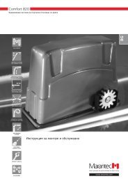
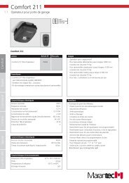
<strong>Comfort</strong> <strong>515</strong> <strong>accu</strong> / <strong>Control</strong> <strong>x.51</strong> <strong>accu</strong><br />
Operator system for Hinged Gates<br />
Manual for installation and operation<br />
GB
1. Meaning of symbols<br />
<strong>Control</strong>s and motor unit symbols Advice<br />
Photocell or closing edge safety device (CESD)<br />
Gate position OPEN<br />
Has no function<br />
Gate position CLOSED<br />
Has no function<br />
Has no function<br />
Impulse<br />
(remote control, external control elements)<br />
Operation<br />
Closing edge safety device<br />
STOP<br />
External control elements<br />
Modular antenna<br />
Type plate, control unit<br />
Type: ________________________________________________<br />
Art. No.: _____________________________________________<br />
Product-No.: __________________________________________<br />
i<br />
Caution!<br />
Danger of personal injury!<br />
The following safety advice must be<br />
observed at all times in order to avoid<br />
personal injury!<br />
Attention!<br />
Danger of material damage!<br />
The following safety advice must be<br />
observed at all times in order to avoid<br />
material damage!<br />
Advice / Tip<br />
Check<br />
Reference<br />
Type plate, motor unit 1<br />
Type: ________________________________________________<br />
Art. No.: _____________________________________________<br />
Product-No.: __________________________________________<br />
Type plate, motor unit 2 (only double wing)<br />
Type: ________________________________________________<br />
Art. No.: _____________________________________________<br />
Product-No.: __________________________________________<br />
2 Manual for installation and operation, <strong>Comfort</strong> <strong>515</strong> <strong>accu</strong> GB (#85512)
2. Table of contents<br />
1. Meaning of symbols . . . . . . . . . . . . . . . . . . . . . . . . . . . . . . . . . . . . . . . . . . . . . . . . . . . . . . . . . . . . . . . . . . . .2<br />
2. Table of contents . . . . . . . . . . . . . . . . . . . . . . . . . . . . . . . . . . . . . . . . . . . . . . . . . . . . . . . . . . . . . . . . . . . . . . .3<br />
3. General safety advice . . . . . . . . . . . . . . . . . . . . . . . . . . . . . . . . . . . . . . . . . . . . . . . . . . . . . . . . . . . . . . . . . . .4<br />
4. Product overview . . . . . . . . . . . . . . . . . . . . . . . . . . . . . . . . . . . . . . . . . . . . . . . . . . . . . . . . . . . . . . . . . . . . . .7<br />
4.1 <strong>Comfort</strong> <strong>515</strong> <strong>accu</strong> supply package . . . . . . . . . . . . . . . . . . . . . . . . . . . . . . . . . . . . . . . . . . . . . . . . . . . . . .7<br />
4.2 Dimensions . . . . . . . . . . . . . . . . . . . . . . . . . . . . . . . . . . . . . . . . . . . . . . . . . . . . . . . . . . . . . . . . . . . . . .10<br />
4.3 Gate variations . . . . . . . . . . . . . . . . . . . . . . . . . . . . . . . . . . . . . . . . . . . . . . . . . . . . . . . . . . . . . . . . . . . .10<br />
5. Preparation for mounting . . . . . . . . . . . . . . . . . . . . . . . . . . . . . . . . . . . . . . . . . . . . . . . . . . . . . . . . . . . . . .11<br />
5.1 General notes . . . . . . . . . . . . . . . . . . . . . . . . . . . . . . . . . . . . . . . . . . . . . . . . . . . . . . . . . . . . . . . . . . . .11<br />
5.2 Checks . . . . . . . . . . . . . . . . . . . . . . . . . . . . . . . . . . . . . . . . . . . . . . . . . . . . . . . . . . . . . . . . . . . . . . . . . .11<br />
5.3 Cabling layout . . . . . . . . . . . . . . . . . . . . . . . . . . . . . . . . . . . . . . . . . . . . . . . . . . . . . . . . . . . . . . . . . . . .12<br />
6. Installation . . . . . . . . . . . . . . . . . . . . . . . . . . . . . . . . . . . . . . . . . . . . . . . . . . . . . . . . . . . . . . . . . . . . . . . . . . .13<br />
6.1 Mounting conditions . . . . . . . . . . . . . . . . . . . . . . . . . . . . . . . . . . . . . . . . . . . . . . . . . . . . . . . . . . . . . . .13<br />
6.2 Prepare installation dimensions . . . . . . . . . . . . . . . . . . . . . . . . . . . . . . . . . . . . . . . . . . . . . . . . . . . . . . .14<br />
6.3 Fixing the post bracket . . . . . . . . . . . . . . . . . . . . . . . . . . . . . . . . . . . . . . . . . . . . . . . . . . . . . . . . . . . . . .18<br />
6.4 Fixing the motor unit to the post bracket . . . . . . . . . . . . . . . . . . . . . . . . . . . . . . . . . . . . . . . . . . . . . . . .19<br />
6.5 Fixing the control unit . . . . . . . . . . . . . . . . . . . . . . . . . . . . . . . . . . . . . . . . . . . . . . . . . . . . . . . . . . . . . .19<br />
6.6 Connection of control elements . . . . . . . . . . . . . . . . . . . . . . . . . . . . . . . . . . . . . . . . . . . . . . . . . . . . . .20<br />
6.7 Connecting the operator to the controls . . . . . . . . . . . . . . . . . . . . . . . . . . . . . . . . . . . . . . . . . . . . . . . .25<br />
6.8 Cabling for the operator system . . . . . . . . . . . . . . . . . . . . . . . . . . . . . . . . . . . . . . . . . . . . . . . . . . . . . .27<br />
6.9 Setting the CLOSED and OPEN gate positions . . . . . . . . . . . . . . . . . . . . . . . . . . . . . . . . . . . . . . . . . . . .28<br />
6.10 Mounting the gate bracket . . . . . . . . . . . . . . . . . . . . . . . . . . . . . . . . . . . . . . . . . . . . . . . . . . . . . . . . . .30<br />
6.11 Release . . . . . . . . . . . . . . . . . . . . . . . . . . . . . . . . . . . . . . . . . . . . . . . . . . . . . . . . . . . . . . . . . . . . . . . . .30<br />
7. Hand transmitter . . . . . . . . . . . . . . . . . . . . . . . . . . . . . . . . . . . . . . . . . . . . . . . . . . . . . . . . . . . . . . . . . . . . . .31<br />
7.1 Operation and accessories . . . . . . . . . . . . . . . . . . . . . . . . . . . . . . . . . . . . . . . . . . . . . . . . . . . . . . . . . . .31<br />
7.2 Hand transmitter coding . . . . . . . . . . . . . . . . . . . . . . . . . . . . . . . . . . . . . . . . . . . . . . . . . . . . . . . . . . . .32<br />
8. Initial operation . . . . . . . . . . . . . . . . . . . . . . . . . . . . . . . . . . . . . . . . . . . . . . . . . . . . . . . . . . . . . . . . . . . . . . .33<br />
8.1 Connecting the modular antenna . . . . . . . . . . . . . . . . . . . . . . . . . . . . . . . . . . . . . . . . . . . . . . . . . . . . .33<br />
8.2 Overview of the control unit . . . . . . . . . . . . . . . . . . . . . . . . . . . . . . . . . . . . . . . . . . . . . . . . . . . . . . . . .34<br />
8.3 Overview of the display functions . . . . . . . . . . . . . . . . . . . . . . . . . . . . . . . . . . . . . . . . . . . . . . . . . . . . .34<br />
8.4 Express programming . . . . . . . . . . . . . . . . . . . . . . . . . . . . . . . . . . . . . . . . . . . . . . . . . . . . . . . . . . . . . .35<br />
8.5 Function test . . . . . . . . . . . . . . . . . . . . . . . . . . . . . . . . . . . . . . . . . . . . . . . . . . . . . . . . . . . . . . . . . . . . .37<br />
9. Extended operator functions . . . . . . . . . . . . . . . . . . . . . . . . . . . . . . . . . . . . . . . . . . . . . . . . . . . . . . . . . . . .38<br />
9.1 General notes on extended operator functions . . . . . . . . . . . . . . . . . . . . . . . . . . . . . . . . . . . . . . . . . . .38<br />
9.2 Programming structure for extended operator functions (Example for Level 2, Menu 2) . . . . . . . . . . . . .39<br />
9.3 General overview of the programmable functions . . . . . . . . . . . . . . . . . . . . . . . . . . . . . . . . . . . . . . . . .40<br />
9.4 Functions overview for the levels . . . . . . . . . . . . . . . . . . . . . . . . . . . . . . . . . . . . . . . . . . . . . . . . . . . . . .41<br />
10. Messages . . . . . . . . . . . . . . . . . . . . . . . . . . . . . . . . . . . . . . . . . . . . . . . . . . . . . . . . . . . . . . . . . . . . . . . . . . . .50<br />
10.1 Status messages . . . . . . . . . . . . . . . . . . . . . . . . . . . . . . . . . . . . . . . . . . . . . . . . . . . . . . . . . . . . . . . . . .50<br />
10.2 Fault messages . . . . . . . . . . . . . . . . . . . . . . . . . . . . . . . . . . . . . . . . . . . . . . . . . . . . . . . . . . . . . . . . . . . .50<br />
10.3 Rectifying faults . . . . . . . . . . . . . . . . . . . . . . . . . . . . . . . . . . . . . . . . . . . . . . . . . . . . . . . . . . . . . . . . . . .52<br />
11. Attachment . . . . . . . . . . . . . . . . . . . . . . . . . . . . . . . . . . . . . . . . . . . . . . . . . . . . . . . . . . . . . . . . . . . . . . . . . .55<br />
11.1 Connection diagram <strong>Comfort</strong> <strong>515</strong> <strong>accu</strong> . . . . . . . . . . . . . . . . . . . . . . . . . . . . . . . . . . . . . . . . . . . . . . . . .55<br />
11.2 Technical Data for <strong>Comfort</strong> <strong>515</strong> <strong>accu</strong> . . . . . . . . . . . . . . . . . . . . . . . . . . . . . . . . . . . . . . . . . . . . . . . . . . .56<br />
11.3 Declaration of incorporation . . . . . . . . . . . . . . . . . . . . . . . . . . . . . . . . . . . . . . . . . . . . . . . . . . . . . . . . .57<br />
11.4 EC Declaration of Conformity . . . . . . . . . . . . . . . . . . . . . . . . . . . . . . . . . . . . . . . . . . . . . . . . . . . . . . . .57<br />
Manual for installation and operation, <strong>Comfort</strong> <strong>515</strong> <strong>accu</strong> GB (#85512) 3
3. General safety advice<br />
Please read carefully!<br />
Target group<br />
This operator system may only be installed, connected and put into operation by qualified and trained professionals!<br />
Qualified and trained specialist personnel are persons<br />
- who have knowledge of the general and special safety regulations,<br />
- who have knowledge of the relevant electro-technical regulations,<br />
- with training in the use and maintenance of suitable safety equipment,<br />
- who are sufficiently trained and supervised by qualified electricians,<br />
- who are able to recognise the particular hazards involved when working with electricity,<br />
- with knowledge regarding applications of the EN 12635 standard (installation and usage requirements).<br />
Warranty<br />
For an operations and safety warranty, the advice in this instruction manual has to be observed. Disregarding these<br />
warnings may lead to personal injury or material damage. If this advice is disregarded, the manufacturer will not be<br />
liable for damages that might occur.<br />
Batteries, fuses and bulbs are excluded from warranty.<br />
To avoid installation errors and damage to the gate and operator system, it is imperative that the installation<br />
instructions are followed. The system may only be used after thoroughly reading the respective mounting and<br />
installation instructions.<br />
The installation and operating instructions are to be given to the gate system user, who must keep them safe.<br />
They contain important advice for operation, checks and maintenance.<br />
This item is produced according to the directives and standards mentioned in the Manufacturer's Declaration and in<br />
the Declaration of Conformity. The product has left the factory in perfect condition with regard to safety.<br />
Power-operated windows, doors and gates must be checked by an expert (and this must be documented) before they<br />
are put into operation and thereafter as required, but at least once a year.<br />
Correct use<br />
The operator system is designed exclusively for opening and closing hinged doors and gates.<br />
Gate requirements<br />
The short version operator system - <strong>Comfort</strong> <strong>515</strong> is suitable for:<br />
- hinged doors and gates with a gate wing width of 2.5 m and a gate wing weight of 200 kg.<br />
Beside the advice in these instructions, please observe the general safety and accident prevention regulations!<br />
Our sales and supply terms and conditions are effective.<br />
4 Manual for installation and operation, <strong>Comfort</strong> <strong>515</strong> <strong>accu</strong> GB (#85512)
3. General safety advice<br />
Please read carefully!<br />
Information on installing the operator system<br />
• Ensure that the gate is in good mechanical condition.<br />
• Ensure that the gate opens and closes properly.<br />
• Remove all unnecessary components from the gate (e.g. cables, chains, brackets).<br />
• Render any installations inoperable that will no longer be needed after the operator system has been installed.<br />
• Before commencing cabling works it is very important to disconnect the operator system from the electricity supply.<br />
Ensure that the electricity supply remains disconnected throughout the cabling works.<br />
• Adhere to the local protection regulations.<br />
• Lay the electricity supply cables and control cables; these MUST be laid separately. The controls voltage is 24 V DC.<br />
• Install all the impulse transmitters and control devices (e.g. remote control buttons) within sight of the gate and at a<br />
safe distance from the moving parts of the gate. A minimum installation height of 1.5 m must be observed.<br />
• Ensure that no part of the gate extends across public footways or roads when the installation is complete.<br />
Information on commissioning the operator system<br />
After initial operation, the persons responsible for operating the gate system, or their representatives must be<br />
familiarised with the use of the system.<br />
• The rechargeable battery unit must be fully charged before the door system is put into operation.<br />
• Make sure that children cannot access the gate control unit.<br />
• Before moving the gate, make sure that there are neither persons nor objects in the operating range of the gate.<br />
• Test all existing emergency command devices.<br />
• Never insert your hands into a running gate or moving parts.<br />
• Pay attention to any parts of the gate system that could cause crushing or shearing damage or accidents.<br />
The EN 13241-1 regulations must be observed.<br />
Information on servicing the operator system<br />
To ensure proper operation, the following items must be checked regularly and repaired if necessary.<br />
Before any works to the gate system are undertaken, the operator system must be disconnected from the mains.<br />
• Check once a month that the operator system stops and reverses in every position when the gate touches an<br />
obstacle. Place an obstacle in the path of the gate to check this.<br />
• Check the settings of the OPEN and CLOSE automatic cut-out function.<br />
• Check all movable parts of the gate and operator system.<br />
• Check the gate system for signs of wear or damage.<br />
• Check whether the gate can be easily moved by hand.<br />
Information on cleaning the operator system<br />
Never use water jets, high pressure cleaners, acids or bases for cleaning.<br />
Manual for installation and operation, <strong>Comfort</strong> <strong>515</strong> <strong>accu</strong> GB (#85512) 5
3. General safety advice<br />
Please read carefully!<br />
Advice on handling the rechargeable battery unit<br />
• Only charge the rechargeable battery unit in well ventilated rooms, otherwise there is a risk of explosion.<br />
• Never short-circuit the rechargeable battery unit.<br />
If, despite the warning given via the operator system, the rechargeable battery unit is operated whilst the battery is low,<br />
a defect could result due to deep charge.<br />
To prevent deep discharge of the rechargeable battery unit, the rechargeable battery unit must be recharged at least<br />
once every 6 months if not in use.<br />
The lead-acid batteries in the rechargeable battery unit can be returned, for recycling, to shops that sell batteries.<br />
Advice on handling the plug-in battery charger<br />
Hazards may arise when operating battery chargers:<br />
- Danger of explosion<br />
(due to the formation of explosive gases when charging the lead-acid battery),<br />
- Danger of fire and short-circuit<br />
(due to electric shock in moist conditions).<br />
To prevent any danger:<br />
• Ensure that the area is adequately ventilated.<br />
• Avoid fire and naked lights.<br />
• Only use the battery charger in dry rooms.<br />
• Protect the device from moisture.<br />
• Protect the device from oils and sharp edges.<br />
• Check the device regularly for signs of damage.<br />
6 Manual for installation and operation, <strong>Comfort</strong> <strong>515</strong> <strong>accu</strong> GB (#85512)
4. Product overview<br />
4.1 <strong>Comfort</strong> <strong>515</strong> <strong>accu</strong> supply package<br />
The <strong>Comfort</strong> <strong>515</strong> standard delivery package comprises:<br />
- motor unit<br />
- controls<br />
- fixing materials for controls<br />
and motor unit<br />
- remote control<br />
The <strong>Comfort</strong> <strong>515</strong> is available in the following versions,<br />
as required:<br />
Single wing gate system<br />
(Short version – <strong>Comfort</strong> <strong>515</strong>)<br />
4.1 / 1<br />
2<br />
1<br />
1 Motor unit with short connection cable (1.5 m)<br />
2 Key (2x)<br />
Single wing gate system<br />
(Long version – <strong>Comfort</strong> <strong>515</strong> L)<br />
4.1 / 2<br />
2<br />
1<br />
1 Motor unit with short connection cable (1.5 m)<br />
2 Key (2x)<br />
Double wing gate system<br />
(Short version – <strong>Comfort</strong> <strong>515</strong>)<br />
Manual for installation and operation, <strong>Comfort</strong> <strong>515</strong> <strong>accu</strong> GB (#85512) 7<br />
4.1 / 3<br />
5<br />
3<br />
4<br />
3 Motor unit with short connection cable (1.5 m)<br />
4 Motor unit with long connection cable (8.5 m)<br />
5 Key (4x)<br />
Double wing gate system<br />
(Long version – <strong>Comfort</strong> <strong>515</strong> L)<br />
4.1 / 4<br />
5<br />
3<br />
4<br />
3 Motor unit with short connection cable (1.5 m)<br />
4 Motor unit with long connection cable (8.5 m)<br />
5 Key (4x)
4. Product overview<br />
<strong>Control</strong> unit<br />
4.1 / 5<br />
6<br />
6 <strong>Control</strong> <strong>x.51</strong> <strong>accu</strong><br />
7 Handle<br />
Mounting kit for control unit<br />
4.1 / 6<br />
8<br />
9<br />
!¯<br />
!”<br />
!#<br />
7<br />
!£<br />
!Ø<br />
8 Screws 3.5 x 32 (4x)<br />
9 Wall plugs S6 (4x)<br />
10 Spacer elements (2x)<br />
11 Screw fixing insert with 2 flat cable openings<br />
12 M20 screw fixing with flat cable insert<br />
13 M20 screw fixing with round cable insert<br />
14 M16 screw fixing with round cable insert<br />
Remote control<br />
4.1 / 7<br />
15 Hand transmitter<br />
16 Module antenna<br />
17 Transmission plug<br />
18 Sun visor clip<br />
Single wing gate system installation set<br />
4.1 / 8<br />
!·<br />
„¯<br />
„∏<br />
„”<br />
„#<br />
19 Wood screws 8 x 60 (4x)<br />
20 Wall plugs S10 (4x)<br />
21 Bolts 10 x 49 (2x)<br />
22 Locking plates (2x)<br />
23 Cover cap<br />
24 M8 x 25 (8x)<br />
25 Nuts M8 (8x)<br />
26 Gate bracket<br />
27 Post bracket<br />
8 Manual for installation and operation, <strong>Comfort</strong> <strong>515</strong> <strong>accu</strong> GB (#85512)<br />
!5<br />
!˜<br />
!^<br />
!\<br />
„£<br />
„5<br />
„^<br />
„\
4. Product overview<br />
Double wing gate system installation set<br />
4.1 / 9<br />
4.1 / 10<br />
!·<br />
„¯<br />
„∏<br />
„”<br />
„#<br />
!·<br />
„¯<br />
„∏<br />
„”<br />
„#<br />
19 Wood screws 8 x 60 (8x)<br />
20 Wall plugs S10 (8x)<br />
21 Bolts 10 x 49 (4x)<br />
22 Locking plates (4x)<br />
23 Cover caps (2x)<br />
24 M8 x 25 (16x)<br />
25 Nuts M8 (16x)<br />
26 Gate brackets (2x)<br />
27 Post brackets (2x)<br />
„£<br />
„5<br />
„^<br />
„\<br />
„£<br />
„5<br />
„^<br />
„\<br />
Battery operation version<br />
4.1 / 11<br />
§¯<br />
28 Rechargeable battery unit<br />
29 Cable loom of rechargeable battery unit<br />
30 Plug mains supply<br />
Solar version<br />
4.1 / 12<br />
31 Fixing bracket for solar module (2x)<br />
32 Solar module incl. 7.5 m connection cable<br />
33 Set of screws, M5 x 12, incl. M5 nuts (4x)<br />
34 Set of screws, 8 x 45 (4x)<br />
Manual for installation and operation, <strong>Comfort</strong> <strong>515</strong> <strong>accu</strong> GB (#85512) 9<br />
“˜<br />
“·<br />
§£<br />
§#<br />
§”<br />
§»
4. Product overview<br />
4.2 Dimensions<br />
Short version – <strong>Comfort</strong> <strong>515</strong><br />
4.2 / 1<br />
ø 10.1<br />
400<br />
39<br />
68<br />
755<br />
197.5<br />
722.4<br />
Long version – <strong>Comfort</strong> <strong>515</strong> L<br />
4.2 / 2<br />
ø 10.1<br />
600<br />
39<br />
68<br />
922.4<br />
955<br />
197.5<br />
122<br />
122<br />
14.7<br />
14.7<br />
ø 10.1<br />
47.2<br />
ø 10.1<br />
47.2<br />
4.3 Gate variations<br />
The standard supply package is suitable for<br />
the following types of gate.<br />
Single wing gate system<br />
4.3 / 1<br />
Double wing gate system<br />
10 Manual for installation and operation, <strong>Comfort</strong> <strong>515</strong> <strong>accu</strong> GB (#85512)<br />
4.3 / 2
5. Preparation for mounting<br />
5.1 General notes<br />
The pictures in these instructions are not true-to-scale.<br />
Dimensions are always given in millimetres (mm)!<br />
The motor unit and the controls must be installed on<br />
the inside of the gate system.<br />
For correct mounting you will need the following<br />
tools:<br />
5.1 / 1<br />
10 + 13<br />
2 5<br />
ø 6,5<br />
M 8<br />
13 2<br />
ø 6<br />
ø 10<br />
5.2 Checks<br />
Attention!<br />
In order to guarantee correct<br />
mounting, carry out the following<br />
checks before installing.<br />
Supply package<br />
• Check the package to ensure that all the parts are<br />
included.<br />
• Check that you have all the additional components<br />
that are necessary for your particular installation<br />
requirements.<br />
Gate system *<br />
• Ensure that your gate system has an appropriate<br />
electricity supply connection and a facility<br />
for disconnecting the mains. The minimum<br />
cross-sectional area of the earth cable is<br />
3 x 1.5 mm 2 .<br />
• Ensure that all cables are suitable for outdoor use<br />
(UV resistant and cold resistant).<br />
• Make sure that your gate system has a stop<br />
plate/block in the closing direction.<br />
• Remove the gate fasteners or latches or render them<br />
inoperative.<br />
• Make sure that the gate is easy to move manually.<br />
• Ensure that the following requirements are met:<br />
Width of gate wing:<br />
- <strong>Comfort</strong> <strong>515</strong> min. 1 m - max. 2.5 m<br />
- <strong>Comfort</strong> <strong>515</strong> L min. 1.5 m - max. 3.5 m<br />
Gate height: min. 1.5 m - max. 2.5 m<br />
Weight of gate wing: max. 200 kg<br />
Open area: min. 50%<br />
Gate incline: max. 2%<br />
Advice:<br />
The use of an electric lock is<br />
recommended for a gate wing<br />
wider than 2 m.<br />
* Dependent on the type of operator system used<br />
Manual for installation and operation, <strong>Comfort</strong> <strong>515</strong> <strong>accu</strong> GB (#85512) 11
5. Preparation for mounting<br />
5.3 Cabling layout<br />
5.3 / 1<br />
2 x 0,4 mm 2<br />
i<br />
1<br />
Advice:<br />
This is just an example of a cabling layout; the layout can vary according to the type of gate and the<br />
associated equipment.<br />
2<br />
2 x 0,75 mm 2<br />
7<br />
8<br />
1<br />
!¯<br />
2 x 0,4 mm 2<br />
1 Photocell<br />
2 Photocell<br />
3 Signal light<br />
4 Code button, transponder, ...<br />
5 Key switch<br />
6 Mains isolator switch (mains disconnection facility)<br />
7 Electric lock<br />
2 x 0,75 mm 2<br />
3 x 1,5 mm 2<br />
2 x 0,4 mm 2<br />
8 Stop plate<br />
9 Mains supply cable<br />
10 Cosing edge safety device (CESD)<br />
11 Rechargeable battery unit<br />
12 Solar module*<br />
2 x 0,4 mm 2<br />
3 x 1,5 mm 2<br />
230 V / AC<br />
* Dependent on the type of operator system used<br />
Reference:<br />
For the installation and cabling of the gate sensors, control elements and safety equipment, the relevant<br />
installation instructions must be observed.<br />
2<br />
3<br />
2 x 0,75 mm 2<br />
12 Manual for installation and operation, <strong>Comfort</strong> <strong>515</strong> <strong>accu</strong> GB (#85512)<br />
!”<br />
!»<br />
4<br />
5<br />
9<br />
6
6. Installation<br />
6.1 / 1<br />
Mounting conditions<br />
Attention!<br />
For trouble-free operation, choose the<br />
positions of the brackets such that they<br />
meet all following conditions:<br />
- The motor unit must be located in a<br />
triangle of forces and should not be<br />
parallel to the gate at the OPEN and<br />
CLOSED gate positions.<br />
- The length of travel should be as<br />
large as possible.<br />
C I<br />
A6.1<br />
<br />
<br />
D<br />
B<br />
The mounting positions of the gate bracket (C) and<br />
the post bracket (D) are dependent on your gate<br />
configuration.<br />
The positions of the gate bracket (C) and the post<br />
bracket (D) influence the following factors:<br />
- Opening angle (n)<br />
- Utilisation of the movement stroke (m)<br />
- Gate travelling speed<br />
A triangle of forces is formed by the gate pivot (A),<br />
the post bracket pivot (B) and the gate bracket<br />
pivot (I).<br />
m<br />
n<br />
Motor unit is parallel to the gate<br />
<br />
6.1 / 2<br />
<br />
<br />
Motor unit is within the triangle of forces<br />
6.1 / 3<br />
<br />
Manual for installation and operation, <strong>Comfort</strong> <strong>515</strong> <strong>accu</strong> GB (#85512) 13
6. Installation<br />
6.2 Prepare installation dimensions<br />
The approximate position of the gate bracket and of the post bracket on the gate can be determined with the help of<br />
the dimension tables.<br />
Dimension table for <strong>Comfort</strong> <strong>515</strong><br />
b =<br />
110<br />
b =<br />
130<br />
b =<br />
150<br />
b =<br />
170<br />
b =<br />
190<br />
b =<br />
210<br />
b =<br />
230<br />
b =<br />
250<br />
b =<br />
270<br />
a = 80 a = 100 a = 120 a = 140 a = 160 a = 180 a = 200 a = 220 a = 240 a = 260 a = 280 a = 300<br />
c = 938 c = 970 c = 997 c = 1.040 c = 1.084 c = 1.118 c = 1.122 c = 1.122 c = 1.118 c = 1.122 c = 1.120 c = 1.122<br />
c1 = 255 c1 = 285 c1 = 313 c1 = 357 c1 = 396 c1 = 429 c1 = 438 c1 = 438 c1 = 433 c1 = 438 c1 = 436 c1 = 438<br />
c2 = 50 c2 = 50 c2 = 50 c2 = 50 c2 = 50 c2 = 50 c2 = 50 c2 = 50 c2 = 50 c2 = 50 c2 = 50 c2 = 50<br />
c = 95° d = 105° d = 107° d = 114° d = 124° d = 125° d = 115° d = 108° d = 103° d = 97° d = 96° d = 90°<br />
c = 955 c = 986 c = 1.015 c = 1.048 c = 1.095 c = 1.118 c = 1.122 c = 1.122 c = 1.120 c = 1.118 c = 1.116 c = 1.122<br />
c1 = 273 c1 = 304 c1 = 331 c1 = 364 c1 = 412 c1 = 430 c1 = 438 c1 = 438 c1 = 434 c1 = 430 c1 = 431 c1 = 440<br />
c2 = 50 c2 = 50 c2 = 50 c2 = 50 c2 = 50 c2 = 50 c2 = 50 c2 = 50 c2 = 50 c2 = 50 c2 = 50 c2 = 50<br />
d = 95° d = 105° d = 105° d = 110° d = 120° d = 115° d = 110° d = 104° d = 98° d = 93° d = 92° d = 87°<br />
c = 975 c = 1.005 c = 1.032 c = 1.068 c = 1.110 c = 1.118 c = 1.120 c = 1.122 c = 1.118 c = 1.118 c = 1.122<br />
c1 = 296 c1 = 324 c1 = 350 c1 = 385 c1 = 426 c1 = 434 c1 = 438 c1 = 439 c1 = 436 c1 = 430 c1 = 440<br />
c2 = 50 c2 = 50 c2 = 50 c2 = 50 c2 = 50 c2 = 50 c2 = 50 c2 = 50 c2 = 50 c2 = 50 c2 = 50<br />
d = 95° d = 102° d = 104° d = 110° d = 116° d = 109° d = 103° d = 98° d = 92° d = 90° d = 90°<br />
c = 993 c = 1.022 c = 1.055 c = 1.088 c = 1.125 c = 1.118 c = 1.116 c = 1.105 c = 1.120 c = 1.120<br />
c1 = 316 c1 = 343 c1 = 371 c1 = 405 c1 = 440 c1 = 434 c1 = 435 c1 = 425 c1 = 440 c1 = 440<br />
c2 = 50 c2 = 50 c2 = 50 c2 = 50 c2 = 50 c2 = 50 c2 = 50 c2 = 50 c2 = 50 c2 = 50<br />
d = 95° d = 100° d = 104° d = 108° d = 114° d = 100° d = 97° d = 90° d = 90° d = 87°<br />
c = 1.020 c = 1.045 c = 1.072 c = 1.105 c = 1.120 c = 1.122 c = 1.120 c = 1.116 c = 1.120<br />
c1 = 345 c1 = 363 c1 = 392 c1 = 423 c1 = 438 c1 = 438 c1 = 438 c1 = 435 c1 = 440<br />
c2 = 50 c2 = 50 c2 = 50 c2 = 50 c2 = 50 c2 = 50 c2 = 50 c2 = 50 c2 = 50<br />
d = 93° d = 98° d = 103° d = 106° d = 102° d = 96° d = 92° d = 88° d = 86°<br />
c = 1.035 c = 1.063 c = 1.087 c = 1.117 c = 1.120 c = 1.120 c = 1.122<br />
c1 = 356 c1 = 383 c1 = 407 c1 = 437 c1 = 440 c1 = 440 c1 = 440<br />
c2 = 50 c2 = 50 c2 = 50 c2 = 50 c2 = 50 c2 = 50 c2 = 50<br />
d = 92° d = 97° d = 100° d = 101° d = 95° d = 90° d = 87°<br />
c = 1.065 c = 1.085 c = 1.110 c = 1.119 c = 1.120 c = 1.120<br />
c1 = 390 c1 = 404 c1 = 428 c1 = 438 c1 = 440 c1 = 440<br />
c2 = 50 c2 = 50 c2 = 50 c2 = 50 c2 = 50 c2 = 50<br />
d = 92° d = 97° d = 98° d = 93° d = 88° d = 85°<br />
c = 1.085 c = 1.102 c = 1.117 c = 1.120<br />
c1 = 407 c1 = 425 c1 = 437 c1 = 440<br />
c2 = 50 c2 = 50 c2 = 50 c2 = 50<br />
d = 92° d = 95° d = 92° d = 87°<br />
c = 1.105 c = 1.110<br />
c1 = 433 c1 = 437<br />
c2 = 50 c2 = 50<br />
d = 91° d = 90°<br />
Advice:<br />
The preferred dimensions for the <strong>Comfort</strong> <strong>515</strong> are shaded in grey in the table (for gate wings up to<br />
2.5 m wide and weighing up to 200 kg).<br />
14 Manual for installation and operation, <strong>Comfort</strong> <strong>515</strong> <strong>accu</strong> GB (#85512)
6. Installation<br />
Dimension table for <strong>Comfort</strong> <strong>515</strong> L<br />
b =<br />
110<br />
b =<br />
130<br />
b =<br />
150<br />
c = 1.198<br />
b = c1 = 310<br />
170 c2 = 50<br />
d = 90°<br />
c = 1.219<br />
b = c1 = 332<br />
190 c2 = 50<br />
d = 90°<br />
c = 1.239<br />
b = c1 = 354<br />
210 c2 = 50<br />
d = 90°<br />
c = 1.264<br />
b = c1 = 378<br />
230 c2 = 50<br />
d = 90°<br />
c = 1.285<br />
b = c1 = 400<br />
250 c2 = 50<br />
d = 90°<br />
c = 1.310<br />
b = c1 = 425<br />
270 c2 = 50<br />
d = 90°<br />
a = 80 a = 100 a = 120 a = 140 a = 160 a = 180 a = 200 a = 220 a = 240 a = 260 a = 280 a = 300<br />
c = 1.197 c = 1.240 c = 1.286 c = 1.313 c = 1.342 c = 1.378 c = 1.403 c = 1.435 c = 1.487 c = 1.522<br />
c1 = 312 c1 = 356 c1 = 397 c1 = 428 c1 = 458 c1 = 492 c1 = 518 c1 = 550 c1 = 603 c1 = 640<br />
c2 = 50 c2 = 50 c2 = 50 c2 = 50 c2 = 50 c2 = 50 c2 = 50 c2 = 50 c2 = 50 c2 = 50<br />
d = 105° d = 112° d = 123° d = 125° d = 125° d = 125° d = 125° d = 125° d = 130° d = 135°<br />
c = 1.216 c = 1.256 c = 1.293 c = 1.328 c = 1.360 c = 1.390 c = 1.420 c = 1.450 c = 1.488 c = 1.512<br />
c1 = 331 c1 = 371 c1 = 411 c1 = 445 c1 = 476 c1 = 508 c1 = 533 c1 = 566 c1 = 603 c1 = 629<br />
c2 = 50 c2 = 50 c2 = 50 c2 = 50 c2 = 50 c2 = 50 c2 = 50 c2 = 50 c2 = 50 c2 = 50<br />
d = 105° d = 110° d = 120° d = 125° d = 125° d = 125° d = 125° d = 125° d = 125° d = 125°<br />
c = 1.200 c = 1.234 c = 1.268 c = 1.310 c = 1.344 c = 1.367 c = 1.395 c = 1.420 c = 1.457 c = 1.485 c = 1.510<br />
c1 = 311 c1 = 374 c1 = 385 c1 = 425 c1 = 462 c1 = 486 c1 = 513 c1 = 533 c1 = 570 c1 = 600 c1 = 627<br />
c2 = 50 c2 = 50 c2 = 50 c2 = 50 c2 = 50 c2 = 50 c2 = 50 c2 = 50 c2 = 50 c2 = 50 c2 = 50<br />
d = 95° d = 102° d = 105° d = 115° d = 125° d = 120° d = 120° d = 117° d = 120° d = 120° d = 120°<br />
c = 1.223 c = 1.255 c = 1.282 c = 1.320 c = 1.344 c = 1.378 c = 1.410 c = 1.421 c = 1.443 c = 1.467 c = 1.514<br />
c1 = 335 c1 = 368 c1 = 395 c1 = 431 c1 = 459 c1 = 496 c1 = 525 c1 = 534 c1 = 558 c1 = 583 c1 = 628<br />
c2 = 50 c2 = 50 c2 = 50 c2 = 50 c2 = 50 c2 = 50 c2 = 50 c2 = 50 c2 = 50 c2 = 50 c2 = 50<br />
d = 95° d = 102° d = 102° d = 108° d = 110° d = 115° d = 115° d = 110° d = 110° d = 110° d = 115°<br />
c = 1.248 c = 1.275 c = 1.298 c = 1.330 c = 1.353 c = 1.386 c = 1.419 c = 1.432 c = 1.444 c = 1.483 c = 1.<strong>515</strong><br />
c1 = 360 c1 = 389 c1 = 414 c1 = 445 c1 = 468 c1 = 504 c1 = 533 c1 = 546 c1 = 559 c1 = 581 c1 = 629<br />
c2 = 50 c2 = 50 c2 = 50 c2 = 50 c2 = 50 c2 = 50 c2 = 50 c2 = 50 c2 = 50 c2 = 50 c2 = 50<br />
d = 95° d = 100° d = 100° d = 105° d = 105° d = 110° d = 110° d = 107° d = 105° d = 105° d = 110°<br />
c = 1.268 c = 1.298 c = 1.320 c = 1.342 c = 1.370 c = 1.395 c = 1.415 c = 1.435 c = 1.435 c = 1.476 c = 1.514<br />
c1 = 348 c1 = 410 c1 = 433 c1 = 459 c1 = 485 c1 = <strong>515</strong> c1 = 535 c1 = 549 c1 = 569 c1 = 592 c1 = 624<br />
c2 = 50 c2 = 50 c2 = 50 c2 = 50 c2 = 50 c2 = 50 c2 = 50 c2 = 50 c2 = 50 c2 = 50 c2 = 50<br />
d = 95° d = 100° d = 100° d = 100° d = 102° d = 105° d = 105° d = 105° d = 102° d = 102° d = 105°<br />
c = 1.292 c = 1.315 c = 1.344 c = 1.368 c = 1.388 c = 1.417 c = 1.425 c = 1.443 c = 1.468 c = 1.486 c = 1.510<br />
c1 = 402 c1 = 432 c1 = 460 c1 = 484 c1 = 505 c1 = 530 c1 = 543 c1 = 559 c1 = 584 c1 = 604 c1 = 626<br />
c2 = 50 c2 = 50 c2 = 50 c2 = 50 c2 = 50 c2 = 50 c2 = 50 c2 = 50 c2 = 50 c2 = 50 c2 = 50<br />
d = 95° d = 100° d = 100° d = 100° d = 100° d = 102° d = 102° d = 102° d = 100° d = 100° d = 100°<br />
c = 1.310 c = 1.336 c = 1.362 c = 1.383 c = 1.409 c = 1.420 c = 1.448 c = 1.457 c = 1.485 c = 1.500<br />
c1 = 426 c1 = 454 c1 = 480 c1 = 498 c1 = 528 c1 = 535 c1 = 563 c1 = 573 c1 = 599 c1 = 616<br />
c2 = 50 c2 = 50 c2 = 50 c2 = 50 c2 = 50 c2 = 50 c2 = 50 c2 = 50 c2 = 50 c2 = 50<br />
d = 95° d = 97° d = 97° d = 97° d = 100° d = 97° d = 97° d = 97° d = 97° d = 97°<br />
c = 1.340 c = 1.358 c = 1.380 c = 1.403 c = 1.430 c = 1.444 c = 1.470 c = 1.474 c = 1.490<br />
c1 = 452 c1 = 476 c1 = 496 c1 = 520 c1 = 545 c1 = 560 c1 = 588 c1 = 590 c1 = 606<br />
c2 = 50 c2 = 50 c2 = 50 c2 = 50 c2 = 50 c2 = 50 c2 = 50 c2 = 50 c2 = 50<br />
d = 95° d = 97° d = 97° d = 97° d = 97° d = 97° d = 97° d = 97° d = 96°<br />
Manual for installation and operation, <strong>Comfort</strong> <strong>515</strong> <strong>accu</strong> GB (#85512) 15
6. Installation<br />
a = 80 a = 100 a = 120 a = 140 a = 160 a = 180 a = 200 a = 220 a = 240 a = 260 a = 280 a = 300<br />
c = 1.334 c = 1.357 c = 1.380 c = 1.405 c = 1.422 c = 1.447 c = 1.457 c = 1.478 c = 1.495<br />
b = c1 = 448 c1 = 475 c1 = 498 c1 = 524 c1 = 538 c1 = 563 c1 = 573 c1 = 595 c1 = 610<br />
290 c2 = 50 c2 = 50 c2 = 50 c2 = 50 c2 = 50 c2 = 50 c2 = 50 c2 = 50 c2 = 50<br />
d = 90° d = 95° d = 97° d = 95° d = 95° d = 95° d = 95° d = 95° d = 95°<br />
c = 1.359<br />
b = c1 = 472<br />
310 c2 = 50<br />
d = 90°<br />
c = 1.383<br />
b = c1 = 496<br />
330 c2 = 50<br />
d = 90°<br />
c = 1.406<br />
b = c1 = 522<br />
350 c2 = 50<br />
d = 90°<br />
c = 1.430<br />
b = c1 = 554<br />
370 c2 = 50<br />
d = 90°<br />
c = 1.453<br />
b = c1 = 598<br />
390 c2 = 50<br />
d = 90°<br />
c = 1.481<br />
b = c1 = 595<br />
410 c2 = 50<br />
d = 90°<br />
c = 1.502<br />
b = c1 = 618<br />
430 c2 = 50<br />
d = 90°<br />
c = 1.522<br />
b = c1 = 640<br />
450 c2 = 50<br />
d = 90°<br />
c = 1.380 c = 1.408 c = 1.424 c = 1.448 c = 1.476 c = 1.484 c = 1.502<br />
c1 = 495 c1 = 526 c1 = 540 c1 = 564 c1 = 590 c1 = 598 c1 = 622<br />
c2 = 50 c2 = 50 c2 = 50 c2 = 50 c2 = 50 c2 = 50 c2 = 50<br />
d = 95° d = 97° d = 95° d = 95° d = 95° d = 95° d = 95°<br />
c = 1.403 c = 1.433 c = 1.451 c = 1.470 c = 1.490 c = 1.508<br />
c1 = 518 c1 = 550 c1 = 564 c1 = 585 c1 = 608 c1 = 624<br />
c2 = 50 c2 = 50 c2 = 50 c2 = 50 c2 = 50 c2 = 50<br />
d = 95° d = 97° d = 95° d = 95° d = 95° d = 95°<br />
c = 1.426 c = 1.453 c = 1.474 c = 1.495 c = 1.516<br />
c1 = 543 c1 = 571 c1 = 588 c1 = 611 c1 = 634<br />
c2 = 50 c2 = 50 c2 = 50 c2 = 50 c2 = 50<br />
d = 95° d = 97° d = 95° d = 95° d = 95°<br />
c = 1.452 c = 1.478 c = 1.497 c = 1.518<br />
c1 = 566 c1 = 594 c1 = 614 c1 = 634<br />
c2 = 50 c2 = 50 c2 = 50 c2 = 50<br />
d = 95° d = 97° d = 95° d = 95°<br />
c = 1.475 c = 1.500 c = 1.520<br />
c1 = 590 c1 = 617 c1 = 636<br />
c2 = 50 c2 = 50 c2 = 50<br />
d = 95° d = 97° d = 95°<br />
c = 1.502 c = 1.520<br />
c1 = 618 c1 = 636<br />
c2 = 50 c2 = 50<br />
d = 95° d = 95°<br />
c = 1.520<br />
c1 = 637<br />
c2 = 50<br />
d = 93°<br />
Advice:<br />
The preferred dimensions for the <strong>Comfort</strong> <strong>515</strong> L are shaded in grey in the table (for gate wings up to<br />
3.5 m wide and weighing up to 200 kg).<br />
16 Manual for installation and operation, <strong>Comfort</strong> <strong>515</strong> <strong>accu</strong> GB (#85512)
<br />
6. Installation<br />
Installation dimensions<br />
The installation dimensions depend upon the local<br />
conditions.<br />
The relevant possible combinations are shown in the<br />
dimensions table.<br />
The following applies here:<br />
- The opening angle (d) is determined by the person<br />
installing the gate.<br />
- The installer also measures out the dimension (b),<br />
which is fixed and cannot be changed.<br />
- When the opening angle (d) and dimension (b) are<br />
known, the corresponding dimension (a) and the<br />
CLOSING movement stroke (c1) can be determined<br />
using the dimension table.<br />
- In the ideal case, dimension (a) and dimension (b) are<br />
approximately equal. This ensures that the hinged<br />
gate moves as smoothly as possible.<br />
- The movement stroke in the OPENING direction (c2)<br />
is fixed and always measures 50 mm.<br />
Gate OPEN<br />
/ 1<br />
a6.2<br />
<br />
b<br />
c<br />
c1<br />
Door in OPEN position / opening angle<br />
<br />
6.2 / 2<br />
• Move the gate into the desired OPEN position.<br />
• Measure the opening angle (d).<br />
• Move the door to the CLOSED position.<br />
• Determine dimensions (a) and (b).<br />
The opening angle (d) and dimensions (a) and (b)<br />
provide the value for dimension (c1).<br />
• Determine dimension (c1) using the dimension table.<br />
• Adjust the limit switch to the dimension determined<br />
for (c1).<br />
• Extend the piston rod.<br />
a<br />
a Dimension (a)<br />
b Dimension (b)<br />
c Max. length of motor unit<br />
c1 Movement stroke CLOSING<br />
c2 Movement stroke OPENING<br />
d Max. opening angle<br />
Manual for installation and operation, <strong>Comfort</strong> <strong>515</strong> <strong>accu</strong> GB (#85512) 17<br />
c2<br />
d
6. Installation<br />
6.3 Fixing the post bracket<br />
6.3 / 1<br />
F<br />
E<br />
The vertical position of the gate bracket (E) is dependent<br />
on the position of the gate bracket (F).<br />
• Determine the horizontal position of the gate<br />
bracket (E) on the post with the help of dimension (a).<br />
• Determine the position of the gate bracket (F) on the<br />
gate.<br />
• Transfer the level to the gate bracket (E) using a spirit<br />
level.<br />
• Mark the screw positions on the post.<br />
a<br />
≥ 100<br />
Fixing to a concrete or stone pillar<br />
6.3 / 2<br />
8 x 60<br />
• Screw the gate bracket (E) to the post.<br />
Fixing to a metal post<br />
6.3 / 3<br />
M8 x 25<br />
E<br />
E<br />
• Screw the gate bracket (E) to the post.<br />
• For double wing gate systems, fix the second gate<br />
bracket accordingly on the other side.<br />
18 Manual for installation and operation, <strong>Comfort</strong> <strong>515</strong> <strong>accu</strong> GB (#85512)
Installation<br />
6.4 Fixing the motor unit to the post<br />
bracket<br />
6.4 / 1<br />
• Position the operator on the gate bracket.<br />
Caution!<br />
the cover cap (A).<br />
6.4 / 2<br />
A6.<br />
<br />
<br />
To avoid injury, the redundant hole in<br />
the gate bracket must be sealed using<br />
• Fix the motor unit with the bolt and the locking<br />
plate.<br />
• Push the cover cap (A) into the redundant hole from<br />
above.<br />
• For double wing gate systems, fix the second motor<br />
unit accordingly on the other side.<br />
6.5 Fixing the control unit<br />
6.5 / 1<br />
• Open the control unit.<br />
<br />
<br />
<br />
<br />
<br />
<br />
<br />
<br />
6.5 / 2<br />
3.5 x 32<br />
Attention!<br />
- The control unit must be installed in<br />
such a way that the motor cable can<br />
be fed through the screw fixing at the<br />
base of the control unit.<br />
- The rechargeable battery unit must be<br />
protected by additional measures (e.g.<br />
housing unit) against the effects of<br />
the weather.<br />
A<br />
• Mount the control unit using the spacer elements (A).<br />
i<br />
Reference:<br />
For the installation and cabling of the<br />
rechargeable battery unit and the solar<br />
module, the relevant installation<br />
instructions must be observed.<br />
Manual for installation and operation, <strong>Comfort</strong> <strong>515</strong> <strong>accu</strong> GB (#85512) 19
6. Installation<br />
6.6 Connection of control elements<br />
6.6 / 1<br />
XN81<br />
XV51B<br />
XM70B<br />
XM70A<br />
XV51A<br />
Caution!<br />
Danger of electric shock:<br />
Before any cabling works begin, it must<br />
be ensured that the cables are<br />
disconnected from the power supply.<br />
During cabling works, it must be<br />
ensured that the cables remain<br />
disconnected from the power supply at<br />
all times (e.g. prevent reconnection).<br />
Attention!<br />
In order to avoid damaging the<br />
controls:<br />
- The local safety regulations must be<br />
complied with at all times.<br />
- It is very important that mains cables<br />
are laid separately from control cables.<br />
- The controls voltage must be 24 V DC.<br />
- If external voltages are applied at<br />
terminals XM70A, XV51A, XM70B,<br />
XV51B, XB99, XP54B, XP54A, XP62B,<br />
XP62A or XB70, the entire electronic<br />
system will be destroyed.<br />
- Only potential-free contacts may be<br />
connected to terminals B9, 5, 34, 3<br />
and 8 (XB99).<br />
1<br />
23<br />
7<br />
6 5 4<br />
8<br />
1 2<br />
L N PE 15 16 17<br />
XN70 XP62A XP62B<br />
P<br />
XH01<br />
XB99<br />
XP54B<br />
XB70<br />
XP54A<br />
Label Type / function i<br />
XB70 Connection of modular antenna 8.1<br />
XB99<br />
XH01<br />
XM70A<br />
XM70B<br />
i<br />
Connection of external control<br />
elements<br />
Connection for programmable<br />
output 16/17 (e.g. signal light<br />
24 V DC, 0,5 A, max 10 W)<br />
Electric lock 15/16 (24 V DC)<br />
Connection for motor unit<br />
(MASTER)<br />
Connection for motor unit<br />
(SLAVE)<br />
6.6 / 2<br />
6.6 / 3<br />
6.6 / 4<br />
6.6 / 5<br />
6.6 / 6<br />
6.6 / 7<br />
6.7 / 5<br />
6.7 / 8<br />
6.7 / 5<br />
6.7 / 8<br />
XN70 Connection of battery -<br />
XN81 Connection has no function -<br />
XP54A<br />
XP54B<br />
XP62A<br />
XP62B<br />
Connection for closing edge<br />
safety device, gate travelling<br />
direction CLOSE<br />
Connection for closing edge<br />
safety device, gate travelling<br />
direction OPEN<br />
Connection for photocell,<br />
gate travelling direction CLOSE<br />
Connection for photocell,<br />
gate travelling direction OPEN<br />
6.6 / 8<br />
6.6 / 8<br />
6.6 / 9<br />
6.6 / 9<br />
XV51A Connection has no function -<br />
XV51B Connection has no function -<br />
Reference:<br />
When installing external control<br />
elements, or safety and signal<br />
equipment, the relevant instructions<br />
must be observed.<br />
20 Manual for installation and operation, <strong>Comfort</strong> <strong>515</strong> <strong>accu</strong> GB (#85512)
6. Installation<br />
Terminal XB99<br />
Factory settings:<br />
B9 and 5 bridged<br />
6.6 / 2<br />
M06E039<br />
-XB99<br />
Connection option 1:<br />
6.6 / 3<br />
M06E039<br />
B9 5 34 3 8<br />
-XB99<br />
B9 5 34 3 8<br />
-SB5 12 11<br />
-SB8 14 13<br />
Connection option 2:<br />
6.6 / 4<br />
M06E039<br />
i<br />
-XB99<br />
B9 5 34 3 8<br />
-SB5 12 11<br />
-SB3 4 12 11<br />
Label Type / function<br />
-SB3 14 13<br />
-SB8 14 13<br />
3 Active wing connection<br />
5 Stop connection<br />
8 Impulse connection<br />
34<br />
Connection for closing prevention device<br />
(Photocell)<br />
B9 +24 V DC connection<br />
SB3 Active wing connection<br />
SB5 STOP button<br />
SB8 Impulse button<br />
SB34<br />
Button for closing prevention device<br />
(Photocell) /<br />
Drive system stops and reverses<br />
Reference:<br />
The connection configuration depends<br />
on the programming of the special<br />
functions. Depending on the programming,<br />
impulse or direction buttons can<br />
be connected.<br />
Programming the special functions is<br />
described in Section 9.4 (Level 5).<br />
Manual for installation and operation, <strong>Comfort</strong> <strong>515</strong> <strong>accu</strong> GB (#85512) 21
6. Installation<br />
Connection option 3:<br />
- External radio receiver<br />
6.6 / 5<br />
Advice:<br />
If a closing prevention device<br />
(photocell, timer, …) is connected to<br />
XB99, the controls will recognise it<br />
automatically after “Mains On”<br />
(contact SB34 must be closed).<br />
The photocell can be deactivated later<br />
(Level 8 / Menu 1).<br />
When the contacts of a closing<br />
prevention device are open, the gate<br />
can no longer be closed.<br />
Additional external control elements,<br />
and safety and signal devices with 24 V<br />
connections must be connected to<br />
XB99 and XH01.<br />
M07E027<br />
- XB99<br />
B9 5 34 3 8<br />
- X1 + -<br />
- S1<br />
14 13<br />
1 2<br />
- XH01<br />
15 16 17<br />
Label Type / function<br />
XB99 Connection of external control elements<br />
3 Active wing connection<br />
5 Stop connection<br />
8 Impulse connection<br />
34<br />
Connection for closing prevention device<br />
(Photocell)<br />
B9 24 V DC connection<br />
X1 Connection for external receiver<br />
1<br />
2<br />
Connection of potential-free normally open<br />
contact<br />
Connection of potential-free normally open<br />
contact<br />
+ 24 V DC connection<br />
- GND connection<br />
S1<br />
Normally open contact, receiver,<br />
potential-free<br />
XH01 Connection of control unit output<br />
15 Connection for electric lock, 24 V DC<br />
16 GND connection<br />
17 Connection for programmable output<br />
22 Manual for installation and operation, <strong>Comfort</strong> <strong>515</strong> <strong>accu</strong> GB (#85512)
15 16 17<br />
- KH15<br />
- HH17<br />
6. Installation<br />
Terminals XH01<br />
6.6 / 6<br />
M07E038<br />
Label Type / function<br />
15 / 16 Connection for electric lock, 24 V DC<br />
16 GND connection<br />
16 / 17<br />
- XH01<br />
HH14 Signal light<br />
Connection of programmable output<br />
(24 V DC / 0.5 A)<br />
HH17 Signal light 24 V (max. 10 W)<br />
KH17 User’s relay 24 V<br />
15 16 17<br />
Connection option:<br />
- Connection for signal light with external relay<br />
6.6 / 7<br />
M07E038<br />
- XH01<br />
L<br />
N<br />
- KH17<br />
- YH15<br />
YH15 Electric lock (provided by the customer)<br />
- HH17<br />
15 16 17<br />
A2 A1<br />
11 14 12<br />
- HH14<br />
Terminals XP54A / XP54B<br />
6.6 / 8<br />
M07E037<br />
Label Type / function<br />
P5 GND connection<br />
46<br />
47<br />
- XP54A -<br />
P5<br />
XP54A<br />
47 P5 47<br />
- XP54B -<br />
P5<br />
XP54B<br />
46 P5 46<br />
8K2 8K2 8K2 8K2<br />
Connection for signal of closing edge safety<br />
device<br />
Gate travelling direction OPEN (XP54B)<br />
Connection for signal of closing edge safety<br />
device<br />
Gate travelling direction CLOSE (XP 54A)<br />
Attention!<br />
If an 8.2 kΩ contact strip closing edge<br />
safety device is connected, the 8.2 kΩ<br />
resistors installed at terminals XP54B<br />
closing edge OPEN and XP54A closing<br />
edge CLOSE must be removed.<br />
Manual for installation and operation, <strong>Comfort</strong> <strong>515</strong> <strong>accu</strong> GB (#85512) 23
- AP27<br />
- W1<br />
2 1<br />
6. Installation<br />
Terminals XP62A / XP62B<br />
6.6 / 9<br />
M07E036<br />
Label Type / function<br />
P6 GND connection<br />
26<br />
27<br />
2<br />
- W1<br />
- W2<br />
- XP62A P6 27<br />
- W2<br />
2 1<br />
TX RX<br />
1<br />
- AP27<br />
- AP26<br />
- W1<br />
2 1<br />
- W1<br />
2 1<br />
- XP62A P6 27<br />
- W2<br />
2 1<br />
TX RX<br />
- XP62B P6 26<br />
- W2<br />
2 1<br />
TX RX<br />
Connection for photocell signal<br />
gate travelling direction OPEN (XP62B)<br />
Connection for signal of photocell, gate<br />
travelling direction CLOSE (XP62A)<br />
RX Receiver for the two-wire photocell<br />
TX Transmitter for the two-wire photocell<br />
- AP26<br />
- W1<br />
2 1<br />
- XP62B P6 26<br />
- W2<br />
2 1<br />
TX RX<br />
Advice:<br />
A two-wire photocell connected to<br />
terminals XP62B / XP62A will be<br />
recognised automatically by the<br />
controls after “Mains On”.<br />
The photocell can be deactivated later<br />
(Level 8 / Menu 1).<br />
If the contacts of a closing prevention<br />
device are open, the gate can no longer<br />
be closed.<br />
24 Manual for installation and operation, <strong>Comfort</strong> <strong>515</strong> <strong>accu</strong> GB (#85512)
6. Installation<br />
6.7 Connecting the operator to the<br />
controls<br />
6.7 / 1<br />
6.7 / 2<br />
Advice:<br />
For double-wing gate systems, both<br />
the mains cables must be laid to the<br />
controls.<br />
A1<br />
A2<br />
• Pull the leads out of the motor plug.<br />
6.7 / 3<br />
Attention!<br />
In order to guarantee the protection<br />
grade of the controls, the cables must<br />
be fed through the corresponding<br />
screw fixing (A).<br />
• Feed the cables from the motor units into the control<br />
unit through the screw fixings.<br />
6.7 / 4<br />
Poles:<br />
A1 Brown lead<br />
A2 Green lead<br />
Attention!<br />
To ensure that the motor unit rotates in<br />
the correct direction, the poles of the<br />
plug must be connected correctly.<br />
• Insert the leads into the motor plug.<br />
Manual for installation and operation, <strong>Comfort</strong> <strong>515</strong> <strong>accu</strong> GB (#85512) 25<br />
A1<br />
A2
6. Installation<br />
6.7 / 5<br />
B<br />
C<br />
XM70B<br />
XM70A<br />
1<br />
23<br />
7<br />
6 5 4<br />
8<br />
1<br />
23<br />
7<br />
6 5 4<br />
8<br />
Label Type / function<br />
B<br />
1 2<br />
1 2<br />
L N PE 15 16 17<br />
<strong>Control</strong> module SLAVE<br />
(only for double wing gates)<br />
C <strong>Control</strong> module MASTER<br />
XM70A Connection for motor unit (Master)<br />
XM70B Connection for motor unit (Slave)<br />
P<br />
P<br />
6.7 / 6<br />
6.7 / 7<br />
E SLAVE motor unit<br />
F MASTER motor unit<br />
6.7 / 8<br />
Attention!<br />
To ensure trouble free operation, the<br />
following must be ensured:<br />
- For a single-wing gate system, the<br />
motor unit must always be connected<br />
to the MASTER (XM70A) connection.<br />
- For a double-wing gate system, the<br />
overlap (D) must be taken into<br />
consideration when connecting the<br />
motor units.<br />
F D E<br />
D<br />
E F<br />
XM70B<br />
XM70A<br />
• Connect the motor units to the controls.<br />
L N PE 15 16 17<br />
26 Manual for installation and operation, <strong>Comfort</strong> <strong>515</strong> <strong>accu</strong> GB (#85512)
6. Installation<br />
6.8 Cabling for the operator system<br />
Caution!<br />
- During cabling works, the supply<br />
cables must be disconnected from the<br />
power supply. It must be ensured that<br />
the cables remain disconnected from<br />
the supply for the duration of the<br />
cabling works.<br />
- To avoid damage to persons or to the<br />
rechargeable battery unit, observe the<br />
general safety advice on handling the<br />
rechargeable battery unit and the plugin<br />
battery charger.<br />
Service life<br />
The rechargeable battery unit can supply sufficient<br />
power for<br />
- 15 days (2-wing system)<br />
- 30 days (single wing system)<br />
for 4 movement cycles each day (Opening and Closing)<br />
and under the following conditions:<br />
- The rechargeable battery unit is fully charged<br />
and intact.<br />
- The ambient temperature is approximately 20°C.<br />
- The door is able to move freely.<br />
- There are no other accessories connected that<br />
consume additional power.<br />
Attention!<br />
In order to avoid damaging the<br />
rechargeable battery unit<br />
- the connection to the rechargeable<br />
battery unit has to be carried out in<br />
accordance with the imprinted designation.<br />
- the battery unit has to be removed if<br />
the mains supply is interrupted over a<br />
longer period (mains disconnection,<br />
e.g. during holidays) to prevent damage<br />
due to deep discharge.<br />
Advice:<br />
The optimum period of use is reduced:<br />
- if the ambient temperature is higher<br />
or lower,<br />
- as the rechargeable battery unit<br />
gets older,<br />
- if movement cycles are frequent,<br />
- if accessories are connected.<br />
Voltage indicator<br />
When the rechargeable battery unit is connected to<br />
the operator system, a start-up test is carried out for<br />
the rechargeable battery unit. If the rechargeable<br />
battery unit is not adequately charged, the operator<br />
system reports this via the in-built voltage indicator.<br />
The rechargeable battery unit must then be recharged<br />
without delay. The operator system indicates the<br />
reduction in voltage of the rechargeable battery unit<br />
as follows:<br />
No. of movement cycles<br />
before end of use<br />
LED 6 is on X<br />
8 6<br />
LED 6 flashes X<br />
Stand-by<br />
The operator system switches to “Stand-by” mode<br />
after 20 seconds idle time.<br />
In “Programming mode”, however, “Stand-by" mode<br />
is deactivated.<br />
The operator system can be activated from “Stand-by”<br />
mode as follows:<br />
- by pressing the (+), (-), or (P) button,<br />
- by pressing a button on the programmed handset,<br />
- by pressing an inside button that is connected to the<br />
(XB99) impulse terminals.<br />
- The hold button (B9-5) must be closed.<br />
i<br />
Reference:<br />
For the installation and cabling of the<br />
rechargeable battery unit and the solar<br />
module, the relevant installation<br />
instructions must be observed.<br />
Manual for installation and operation, <strong>Comfort</strong> <strong>515</strong> <strong>accu</strong> GB (#85512) 27
6. Installation<br />
6.9 Setting the CLOSED and OPEN gate<br />
positions<br />
6.9.1 Setting the gate CLOSED position<br />
The CLOSED gate position is determined by the length<br />
of the connecting rod (A).<br />
To achieve the correct CLOSED gate position, the<br />
length of the visible part of the connecting rod (A)<br />
must be equal to the CLOSING movement stroke (c1)<br />
as given in the dimensions table.<br />
The CLOSING movement stroke (c1) is dependent on<br />
the site-dependent dimensions (a) and (b).<br />
6.9.1 / 1<br />
A<br />
i<br />
c1<br />
Reference:<br />
The relevant dimensions are given in<br />
the table in Section 6.2.<br />
Attention!<br />
The connecting rod (A) must be held in<br />
position when closing the gate to<br />
prevent it from turning as the gate<br />
turns.<br />
1<br />
23<br />
7<br />
6 5 4<br />
8<br />
• Drive the gate in the direction of CLOSING by<br />
pressing the (–) button.<br />
1<br />
23<br />
7 8<br />
• Measure the movement stroke (c1): 6 5 4<br />
1 2<br />
1 2<br />
L N PE 15 16 17<br />
P<br />
P<br />
The CLOSING movement stroke (c1) must be adjusted<br />
using the adjusting screw (C) if the values disagree.<br />
Increase the movement stroke:<br />
Turn the adjusting screw (C) in the (+) direction.<br />
Decrease the movement stroke:<br />
Turn the adjusting screw (C) in the (-) direction.<br />
Turning the adjusting screw (C) by 360° adjusts the<br />
movement stroke by 1.25 mm.<br />
6.9.1 / 2<br />
B<br />
• Take off the protective cap (B).<br />
28 Manual for installation and operation, <strong>Comfort</strong> <strong>515</strong> <strong>accu</strong> GB (#85512)
6. Installation<br />
6.9.1 / 3<br />
C<br />
Attention!<br />
The CLOSED position may only be<br />
adjusted using a manual screw driver,<br />
to ensure that the adjusting mechanism<br />
is not damaged.<br />
• Turn the adjusting screw in the (+) or (-) direction to<br />
set the CLOSED position.<br />
• Drive the gate a little in the OPENING direction by<br />
pressing the (+) button.<br />
• Drive the gate back to the CLOSED position by<br />
pressing the (-) button.<br />
• Compare the movement stroke (c1) from the<br />
dimensions table with the movement stroke (c1) as<br />
measured.<br />
• Repeat the process until the CLOSING movement<br />
stroke (c1) from the dimensions table agrees with the<br />
measured CLOSING movement stroke (c1).<br />
6.9.2 Setting the gate OPEN position<br />
The gate OPEN position is pre-set.<br />
6.9.2 / 1<br />
6.9.2 / 2<br />
Attention!<br />
The OPEN position may only be adjusted<br />
using a manual screw driver, to ensure<br />
that the adjusting mechanism is not<br />
damaged.<br />
Advice:<br />
Fine adjustments to the gate OPEN<br />
position can be made by turning the<br />
adjusting screw in the (+) or (-)<br />
directions.<br />
• Fit the protective cap on the motor unit.<br />
Manual for installation and operation, <strong>Comfort</strong> <strong>515</strong> <strong>accu</strong> GB (#85512) 29
6. Installation<br />
6.10 Mounting the gate bracket<br />
6.10 / 1<br />
A<br />
• Drive the motor unit to the gate CLOSED position.<br />
• Secure the gate bracket (A) with the bolt and the<br />
locking plate.<br />
6.10 / 2<br />
M8 x 25<br />
• Close the gate.<br />
Attention!<br />
To ensure the successful mounting of<br />
the gate bracket:<br />
- The motor unit must be in the<br />
CLOSED position.<br />
- The gate must be closed.<br />
A<br />
• Screw the gate bracket (A) to the gate.<br />
• For double-wing gates, mount the second gate<br />
bracket accordingly on the opposite side.<br />
6.11 Release<br />
Releasing<br />
6.11 / 1<br />
• Turn the key through 180°.<br />
• Lift up the red release lever.<br />
• Turn the key 180° in the opposite direction to secure<br />
the released position.<br />
Locking<br />
6.11 / 2<br />
• Turn the key through 180°.<br />
• Press down the red release lever.<br />
• Turn the key 180° in the opposite direction to secure<br />
the locked position.<br />
30 Manual for installation and operation, <strong>Comfort</strong> <strong>515</strong> <strong>accu</strong> GB (#85512)
7. Hand transmitter<br />
7.1 Operation and accessories<br />
Overview<br />
7.1 / 1<br />
Caution!<br />
Children are not allowed to operate the<br />
hand transmitters!<br />
Before operating the hand transmitter,<br />
make sure that there are neither<br />
persons nor objects in the operating<br />
range of the gate.<br />
D<br />
B<br />
C<br />
A Operating button - large<br />
B Operating button - small<br />
C Battery - transmission control light<br />
D Transmission socket<br />
A<br />
D<br />
Another operator system can be operated using the<br />
second operating button.<br />
i<br />
Reference:<br />
The procedure for programming hand<br />
transmitters (remote controls) to<br />
operate the operator system is<br />
described in Section 8.4.3.<br />
Change batteries<br />
7.1 / 2<br />
1<br />
F<br />
E<br />
E Back of hand transmitter<br />
F Battery 3V CR 2032<br />
• Open the back of the hand transmitter (E),<br />
e.g. with a coin.<br />
• Change the battery (F) and observe correct poling.<br />
Accessory<br />
7.1 / 3<br />
Visor clip, for attaching the hand transmitter to a visor<br />
in a car.<br />
Manual for installation and operation, <strong>Comfort</strong> <strong>515</strong> <strong>accu</strong> GB (#85512) 31
7. Hand transmitter<br />
7.2 Hand transmitter coding<br />
7.2.1 Transfer the coding<br />
Using this function it is possible to transfer the coding<br />
of a hand transmitter that has already been<br />
programmed for operating the operator system<br />
(master transmitter) to another hand transmitter.<br />
7.2.1 / 1<br />
Caution!<br />
Before operating the hand transmitter,<br />
ensure that there are neither persons<br />
nor objects in the operating range of<br />
the gate.<br />
• Connect both transmitters with the enclosed<br />
transmission plug.<br />
Advice:<br />
The plug connections on both sides of<br />
the hand transmitter are identical.<br />
7.2.1 / 2<br />
• Actuate the master transmitter and hold the button.<br />
The transmitter LED lights up.<br />
7.2.1 / 3<br />
• Whilst keeping the button on the master transmitter<br />
depressed, press the desired button on the other<br />
hand transmitter.<br />
The LED flashes.<br />
After 1 – 2 seconds, the LED on the newly programmed<br />
transmitter lights up permanently.<br />
The programming procedure is complete.<br />
The coding of the master transmitter has now been<br />
transferred to the other hand transmitter.<br />
• Remove the transmission plug.<br />
Advice:<br />
For multi-channel hand transmitters,<br />
the coding procedure has to be carried<br />
out for each button separately.<br />
32 Manual for installation and operation, <strong>Comfort</strong> <strong>515</strong> <strong>accu</strong> GB (#85512)
7. Hand transmitter<br />
7.2.2 Change coding<br />
If a hand transmitter has been lost, this function can<br />
be used to change the coding of the remaining remote<br />
control transmitters.<br />
7.2.2 / 1<br />
• Connect one end of the transmission plug to the<br />
hand transmitter.<br />
• At the free end of the transmission plug, short-circuit<br />
one of the outer pins with the centre pin adjacent to<br />
it (e.g. using a screw driver).<br />
• Press the desired button on the hand transmitter.<br />
A new code is then generated by the integrated<br />
random coding facility.<br />
The LED flashes quickly.<br />
As soon as the LED lights up permanently, the hand<br />
transmitter has been programmed with a new code.<br />
The button can then be released and the transmission<br />
plug removed.<br />
Advice:<br />
After the hand transmitter has been<br />
re-programmed, the operator system<br />
must also be re-programmed to<br />
respond to the new code.<br />
For multi-channel transmitters, the<br />
programming process must be carried<br />
out for each button separately.<br />
8. Initial operation<br />
8.1 Connecting the modular antenna<br />
8.1 / 1<br />
L N PE 15 16 17<br />
B<br />
A<br />
• Insert the modular antenna (A) into the antenna<br />
socket (B).<br />
Manual for installation and operation, <strong>Comfort</strong> <strong>515</strong> <strong>accu</strong> GB (#85512) 33
8. Initial operation<br />
8.2 Overview of the control unit<br />
8.2 / 1<br />
1<br />
23<br />
7<br />
6 5 4<br />
8<br />
Operating elements<br />
A B D<br />
1 2<br />
P<br />
C<br />
Label Type / function i<br />
A Carousel display 8.3<br />
B<br />
C<br />
D<br />
OPEN button (+)<br />
(e.g. to drive the gate to<br />
the OPEN position or to<br />
increase parameters when<br />
programming)<br />
CLOSE button (-)<br />
(e.g. to drive the gate to<br />
the CLOSED position or to<br />
decrease parameters when<br />
programming)<br />
STOP button (p)<br />
(e.g. to switch to<br />
programming mode or<br />
to save parameters)<br />
-<br />
-<br />
-<br />
8.3 Overview of the display functions<br />
LED displays in operating mode<br />
Legend:<br />
LED off<br />
LED on<br />
LED flashes slowly<br />
LED pulses<br />
LED flashes quickly<br />
Factory default setting<br />
Photocell or the CESD has been interrupted<br />
(display: master only)<br />
Gate moving towards OPEN position<br />
(display: master and slave)<br />
Gate in OPEN position<br />
(display: master and slave)<br />
Gate moving towards CLOSED position<br />
(display: master and slave)<br />
Gate in CLOSED position<br />
(display: master and slave)<br />
Permanent actuation of an external control<br />
element (display: master only)<br />
Remote control is actuated<br />
(display: master only)<br />
Operating voltage<br />
(display: master and slave)<br />
Not possible –<br />
34 Manual for installation and operation, <strong>Comfort</strong> <strong>515</strong> <strong>accu</strong> GB (#85512)
8. Initial operation<br />
8.4 Express programming<br />
8.4.1 General notes on express programming 8.4.2 Programming buttons<br />
Attention!<br />
In order to ensure proper operation,<br />
the express programming must be<br />
carried out at the MASTER control unit.<br />
The following works must be carried out before the<br />
operator can be put into operation successfully:<br />
- The remote control must be programmed in the<br />
express programming procedure.<br />
- The soft running feature must be set up by means of<br />
four learning runs.<br />
After switching on (mains on):<br />
- The controls do not show a gate position signal yet.<br />
- The system always runs in the direction of the OPEN<br />
position after the first impulse.<br />
When the system is already in the OPEN position, only<br />
the display changes after the first impulse, to indicate<br />
the OPEN position. After a second impulse the gate<br />
then runs in the direction of the CLOSED position.<br />
The controls are programmed using the plus (+),<br />
minus (-) and (P) buttons.<br />
If no buttons are pressed within 120 seconds while in<br />
programming mode, the controls revert to operating<br />
mode.<br />
A corresponding message is displayed.<br />
i<br />
Reference:<br />
The messages are explained in<br />
Section 10.<br />
• Carry out the express programming according to the<br />
following procedure.<br />
Manual for installation and operation, <strong>Comfort</strong> <strong>515</strong> <strong>accu</strong> GB (#85512) 35
8. Initial operation<br />
8.4.3 Express programming sequence<br />
Operating<br />
mode<br />
1.<br />
2.<br />
3.<br />
4.<br />
1x >2s
8. Initial operation<br />
8.5 Function test<br />
8.5.1 Learning run for soft-run<br />
• Drive the motor unit (with the gate coupled up) four<br />
times without interruption from the gate CLOSED<br />
position to the OPEN position and back again.<br />
Test:<br />
1.<br />
2.<br />
3.<br />
4.<br />
5.<br />
After pressing the (+) button:<br />
The gate must open and travel to the<br />
saved OPEN end position.<br />
After pressing the (–) button:<br />
The gate must close and travel to the<br />
saved CLOSED end position.<br />
After pressing the hand transmitter<br />
button: The operator system must move<br />
the gate in either the OPEN or CLOSE<br />
direction.<br />
After pressing the hand transmitter<br />
button while the operator system is<br />
running:<br />
The operator system must stop.<br />
When the button is pressed again,<br />
the operator system moves in the<br />
opposite direction.<br />
8.5.2 Checking the automatic cut-out<br />
Caution!<br />
The automatic cut-out must be<br />
correctly programmed for the CLOSE<br />
and OPEN directions to prevent<br />
damage to persons or property.<br />
• Place an obstacle in the path of the gate in both the<br />
OPEN and CLOSE directions.<br />
• For each direction, drive the gate into the obstacle.<br />
The operator system must stop and reverse when<br />
it hits the obstacle.<br />
Advice:<br />
The parameter settings are still saved<br />
if the power supply is disconnected.<br />
Only a reset causes the driving power<br />
settings for the OPEN and CLOSE<br />
directions to revert to the factory<br />
settings.<br />
Manual for installation and operation, <strong>Comfort</strong> <strong>515</strong> <strong>accu</strong> GB (#85512) 37
9. Extended operator functions<br />
9.1 General notes on extended<br />
operator functions<br />
Additional functions can be programmed for the<br />
operator system using the extended functions.<br />
Caution!<br />
Important factory default settings can<br />
be changed using the extended<br />
functions.<br />
All the parameters must be set correctly<br />
to avoid damage to persons or property.<br />
Advice:<br />
The MASTER and SLAVE controls must<br />
be programmed independently of one<br />
another.<br />
Take care to observe the programming<br />
settings of the individual menus.<br />
The programming facility is divided into three areas:<br />
Area 1: Levels<br />
The adjustable functions have been grouped in<br />
8 levels according to the type of function.<br />
Each level can have up to 8 menus.<br />
The (+) and (-) buttons are used to scroll through<br />
the selections within the levels.<br />
Levels that are not used are displayed but cannot be<br />
opened.<br />
Levels-Exit switches from programming to operating<br />
mode.<br />
Ar ea 2: Menu<br />
Each menu sets one parameter.<br />
The (+) and (-) buttons are used to scroll through<br />
the settings within the menus.<br />
Menus that are not in use are skipped over and are<br />
not displayed.<br />
You can return to the first level via Menu-Exit.<br />
Area 3: Parameters<br />
Each function has a maximum of 16 settings.<br />
The (+) and (-) buttons are used to scroll through<br />
the settings for the adjustable parameters.<br />
Parameters that cannot be adjusted are skipped over<br />
and not displayed.<br />
It is not possible to overshoot by pressing the<br />
(+) and (-) buttons.<br />
Pressing the (P) button saves the parameters you<br />
have set.<br />
End Programming<br />
The programming session can be ended in two ways:<br />
1. Via Levels-Exit by pressing the (P) button.<br />
The controls then switch to operating mode.<br />
2. By pressing the (P) button for longer than 5 seconds<br />
at any time and from any area.<br />
The controls then switch to operating mode.<br />
If a parameter had been changed, it will be saved in<br />
the process.<br />
When the programming session ends, all the LEDs light<br />
up and then go out one after the other, in sequence<br />
from 8 to 1.<br />
If no buttons are pressed within 120 seconds while in<br />
programming mode, the controls revert to operating<br />
mode.<br />
A corresponding message is displayed.<br />
i<br />
Legend:<br />
LED off<br />
LED on<br />
LED flashes slowly<br />
LED pulses<br />
LED flashes quickly<br />
Factory default setting<br />
Reference:<br />
- All the available levels and menus are<br />
described in the overview of the<br />
programmable functions (Section 9.3).<br />
- The messages are explained in<br />
Section 10.<br />
Not possible –<br />
38 Manual for installation and operation, <strong>Comfort</strong> <strong>515</strong> <strong>accu</strong> GB (#85512)
9. Extended operator functions<br />
9.2 Programming structure for extended operator functions<br />
(Example for Level 2, Menu 2)<br />
Operating<br />
mode<br />
P<br />
> 10 sec.<br />
P<br />
+<br />
Levels<br />
-<br />
Level 3<br />
Menu<br />
Parameter<br />
-<br />
Level 4<br />
-<br />
Menu 3<br />
P<br />
-<br />
Higher value<br />
-<br />
-<br />
-<br />
+<br />
+<br />
+<br />
+<br />
-<br />
Level 2<br />
+<br />
-<br />
Level 1<br />
+<br />
-<br />
Levels-Exit<br />
+<br />
-<br />
Level 8<br />
+<br />
-<br />
+<br />
-<br />
+<br />
+<br />
-<br />
+<br />
-<br />
+<br />
-<br />
+<br />
-<br />
+<br />
-<br />
P<br />
P<br />
+<br />
-<br />
Menu 2<br />
+<br />
-<br />
Menu 1<br />
+<br />
+<br />
-<br />
+<br />
+<br />
-<br />
+<br />
-<br />
+<br />
Menu-Exit -<br />
(Level 2)<br />
-<br />
+<br />
-<br />
Menu 8<br />
+<br />
-<br />
+<br />
-<br />
P<br />
P<br />
+<br />
+<br />
-<br />
Parameter<br />
+<br />
+<br />
-<br />
-<br />
Lower value<br />
+<br />
-<br />
+<br />
-<br />
+<br />
-<br />
P<br />
> 5 sec.<br />
P<br />
> 5 sec.<br />
P<br />
> 5 sec.<br />
End<br />
programming<br />
Manual for installation and operation, <strong>Comfort</strong> <strong>515</strong> <strong>accu</strong> GB (#85512) 39
9. Extended operator functions<br />
9.3 General overview of the programmable functions<br />
Level 1 – Basic functions<br />
Level 2 – Operator settings<br />
Level 3 – Automatic closing timer<br />
Level Menu Factory default setting<br />
Menu 7: Relay output Signal light<br />
Menu 8: RESET No reset<br />
Menu 1: Required driving power OPEN Setting 5<br />
Menu 2: Required driving power CLOSE Setting 5<br />
Menu 1: Automatic closing timer Deactivated<br />
Menu 3: Gate open duration 15 seconds<br />
Menu 4: Warning time 5 seconds<br />
Menu 5: Start-up warning 0 seconds<br />
Menu 7: Signal light<br />
Level 4 – Remote programming Menu 2: Active wing –<br />
Level 5 – Special function<br />
Level 6 - Variable speed<br />
Level 8 – System settings<br />
Menu 1: Programmable impulse input<br />
Menu 2: Start delay for second motor unit 3 seconds<br />
Menu 4: Lighting duration 180 seconds<br />
Menu 1: Speed OPEN Setting 16<br />
Menu 2: Soft run speed OPEN Setting 7<br />
Menu 4: Speed CLOSE Setting 10<br />
Menu 6: Soft run speed CLOSE Setting 7<br />
Door movement / warning:<br />
light flashes<br />
Door stationary:<br />
light is off (energy-saving)<br />
Active wing /<br />
Impulse (OPEN/STOP/CLOSE)<br />
Menu 1: Photocell Operation without photocell<br />
Menu 2: Closing edge safety device<br />
Menu 4: Operating modes<br />
Gate reverses a little<br />
(OPEN/CLOSE)<br />
Press-and-release<br />
(OPEN/CLOSE)<br />
Menu 5: Function of the direction command transmitters Not active<br />
Menu 6: Function of the impulse command transmitters Stop function active<br />
40 Manual for installation and operation, <strong>Comfort</strong> <strong>515</strong> <strong>accu</strong> GB (#85512)
9. Extended operator functions<br />
9.4 Functions overview for the levels<br />
Level 1 – Basic functions<br />
1 2 3 4 5 6 7 8 9 10 11 12 13 14 15 16<br />
Menu 7: Relay output – terminal 16/17 (MASTER only)<br />
A7 B7 C7 D7 E7 F7 G7 H7 – – – – – – – –<br />
Menu 8: RESET (MASTER + SLAVE)<br />
Reset<br />
No Yes – – – – – – – – – – – – – –<br />
Attention!<br />
After a reset, all the parameters revert to the factory settings.<br />
In order to guarantee the proper operation of the MASTER and SLAVE controls:<br />
- all the required functions must be re-programmed,<br />
- the remote control unit must be re-programmed,<br />
- the MASTER and SLAVE motor units must be driven to the OPEN and CLOSED positions once.<br />
• Reset the SLAVE controls first and complete the controls test.<br />
• Then reset the MASTER controls.<br />
For a different sequence, the control unit must be disconnected from the mains and then switched on again.<br />
i<br />
Advice:<br />
If the automatic closing function (Level 3 / Menu 1) is activated, the relay output (Level 1 / Menu 7) can<br />
be reprogrammed if required.<br />
Reference:<br />
- The function of the signal light (A7) can be adjusted in level 3, menu 7.<br />
- The lighting function (H7) is set in level 5, menu 4.<br />
Menu 7: Relay output<br />
A7 Signal light<br />
B7 Gate position OPEN<br />
C7 Gate CLOSED position<br />
D7 Intermediate position OPEN<br />
E7 Intermediate position CLOSED<br />
F7 Motor starts (wiping impulse – 1 second)<br />
G7 Fault<br />
H7 Lighting<br />
Manual for installation and operation, <strong>Comfort</strong> <strong>515</strong> <strong>accu</strong> GB (#85512) 41
9. Extended operator functions<br />
Level 2 – Operator settings<br />
1 2 3 4 5 6 7 8 9 10 11 12 13 14 15 16<br />
Menu 1: Required driving power OPEN (sensitivity on a scale from 1 to 16*) (MASTER + SLAVE)<br />
OFF 2 3 4 5 6 7 8 9 10 11 12 13 14 15 16<br />
Menu 2: Required driving power CLOSE (sensitivity on a scale from 1 to 16*) (MASTER + SLAVE)<br />
OFF 2 3 4 5 6 7 8 9 10 11 12 13 14 15 16<br />
*The higher the setting, the higher the driving power.<br />
Level 3 - Automatic closing timer<br />
1 2 3 4 5 6 7 8 9 10 11 12 13 14 15 16<br />
Menu 1: Automatic closing timer (MASTER only)<br />
A1 B1 C1 D1 E1 F1 G1 H1 – – – – – – – –<br />
Menu 3: Gate open duration (in seconds) (MASTER only)<br />
2 5 10 15 20 25 30 35 40 50 80 100 120 150 180 255<br />
Menu 4: Warning time (in seconds) (MASTER only)<br />
1 2 5 10 15 20 25 30 35 40 45 50 55 60 65 70<br />
Menu 5: Start-up warning (in seconds) (MASTER only)<br />
0 1 2 3 4 5 6 7 – – – – – – – –<br />
Menu 7: Signal light<br />
A7 B7 C7 D7 E7 F7 – – – – – – – – – –<br />
Advice:<br />
- The automatic closing timer can only be programmed if a photocell barrier is connected.<br />
- The functions in Menu 1 can be altered as desired via the time settings in Menus 3, 4 and 5.<br />
42 Manual for installation and operation, <strong>Comfort</strong> <strong>515</strong> <strong>accu</strong> GB (#85512)
9. Extended operator functions<br />
Menu 1: Automatic closing timer<br />
Setting<br />
Menu 7: Signal light<br />
Advice:<br />
Without a connected photocell or closing prevention device, only parameter A1 can be adjusted.<br />
Setting Gate movement / Warning Gate stoppage<br />
A7 flashing OFF (Electricity saving)<br />
B7 lighting OFF (Electricity saving)<br />
C7 flashing flashing<br />
D7 lighting lighting<br />
E7 flashing lighting<br />
F7 lighting flashing<br />
i<br />
Gate open<br />
duration<br />
(seconds)<br />
Warning time<br />
(seconds)<br />
Automatic<br />
closing timer<br />
Reference:<br />
The signal light connection can be adjusted in level 1, menu 7.<br />
other functions<br />
A1 - - deactivated -<br />
B1 15 5 activated<br />
C1 30 5 activated<br />
D1 60 8 activated<br />
E1 15 5 activated<br />
F1 30 5 activated<br />
G1 60 8 activated<br />
H1 unlimited 3 activated<br />
Extension of door OPEN time only through impulse signal<br />
(button, hand transmitter)<br />
Interruption of the gate open duration after the photocell barrier<br />
has been driven past<br />
Closes after the photocell barrier has been driven past / closing<br />
prevention<br />
Manual for installation and operation, <strong>Comfort</strong> <strong>515</strong> <strong>accu</strong> GB (#85512) 43
9. Extended operator functions<br />
Level 4 – Remote programming<br />
Menu 2: Active wing – remote impulse to operate one gate wing only (MASTER ONLY)<br />
Level 5 – Special function<br />
LED 7 flashes slowly -> press hand transmitter button -> LED 7 flashes quickly<br />
1 2 3 4 5 6 7 8 9 10 11 12 13 14 15 16<br />
Menu 1: Programmable impulse input - XB99 (MASTER ONLY)<br />
A1 B1 – – – – – – – – – – – – – –<br />
Menu 2: Start-delay for second motor unit (MASTER ONLY)<br />
A2 B2 C2 D2 E2 F2 G2 H2 I2 J2 K2 L2 M2 N2 O2 P2<br />
Menu 4: Lighting duration (in seconds) – Terminal 16/17<br />
2 5 10 15 20 25 30 35 40 50 80 100 120 150 180 255<br />
Menu 1: Programmable impulse input<br />
A1 Connection option 1:<br />
Terminal B9/3: Active wing<br />
Terminal B9/8: Impulse (OPEN/STOP/CLOSE)<br />
B1 Connection option 2:<br />
Terminal B9/3: Direction command transmitter, CLOSE<br />
Terminal B9/8: Direction command transmitter, OPEN<br />
i<br />
Reference:<br />
The programming of the special function is dependent on terminal XB99.<br />
Terminal XB99 is described in Section 6.6.<br />
The programmed lighting time is only active if the relay output (Level 1 / Menu 7) is set to<br />
“Lighting” (H7).<br />
44 Manual for installation and operation, <strong>Comfort</strong> <strong>515</strong> <strong>accu</strong> GB (#85512)
9. Extended operator functions<br />
Menu 2: Start-delay for second motor unit (in seconds) (MASTER ONLY)<br />
Separate adjusting facilities for OPEN and CLOSE direction of travel (in seconds)<br />
Setting OPEN direction CLOSE direction<br />
A2 Deceleration deactivated<br />
B2 1 1<br />
C2<br />
D2 3<br />
E2 4<br />
F2 2<br />
5<br />
G2 6<br />
H2 10<br />
I2 15<br />
J2<br />
K2 4<br />
L2 5<br />
M2 3<br />
6<br />
N2 10<br />
O2 15<br />
P2 20<br />
Legend:<br />
LED off<br />
Manual for installation and operation, <strong>Comfort</strong> <strong>515</strong> <strong>accu</strong> GB (#85512) 45<br />
LED on<br />
LED flashes slowly<br />
LED pulses<br />
LED flashes quickly<br />
Factory default setting<br />
Not possible –<br />
2<br />
3
9. Extended operator functions<br />
Level 6 - Variable speed<br />
1 2 3 4 5 6 7 8 9 10 11 12 13 14 15 16<br />
Menu 1: Speed OPEN (in increments) (MASTER + SLAVE)<br />
– – – – – – 7 8 9 10 11 12 13 14 15 16<br />
Menu 2: Soft run speed OPEN (in increments) (MASTER + SLAVE)<br />
– – – – 5 6 7 8 9 10 11 12 13 14 15 16<br />
Menu 4: Speed CLOSE (in increments) (MASTER + SLAVE)<br />
– – – – – – 7 8 9 10 11 12 13 14 15 16<br />
Menu 8: Soft run position CLOSED (MASTER + SLAVE)<br />
i<br />
– – – – 5 6 7 8 9 10 11 12 13 14 15 16<br />
Advice:<br />
After altering the driving speed, the system must be disconnected from the mains once when in the<br />
CLOSED position.<br />
After the power has been switched on again and four learning runs have been carried out, the operator<br />
system is ready for operation.<br />
Reference:<br />
If changes are made in Menus 1, 2, 4 and 6 in Level 6, a new performance check must be carried out<br />
(Section 8.5).<br />
46 Manual for installation and operation, <strong>Comfort</strong> <strong>515</strong> <strong>accu</strong> GB (#85512)
9. Extended operator functions<br />
Level 8 – System settings<br />
1 2 3 4 5 6 7 8 9 10 11 12 13 14 15 16<br />
Menu 1: Photocell (MASTER ONLY)<br />
A1 B1 C1 D1 E1 F1 G1 H1 I1 J1 – – – – – –<br />
Menu 2: Closing edge safety device (MASTER + SLAVE)<br />
A2 B2 C2 D2 – – – – – – – – – – – –<br />
Menu 4: Operating modes (MASTER ONLY)<br />
A4 B4 C4 D4 – – – – – – – – – – – –<br />
Menu 5: Function of the direction command transmitters (MASTER ONLY)<br />
A5 B5 – – – – – – – – – – – – – –<br />
Menu 6: Function of the impulse command transmitters (MASTER ONLY)<br />
A6 B6 – – – – – – – – – – – – – –<br />
Attention!<br />
If a photocell is connected, it is automatically recognised by the controls after MAINS ON.<br />
The photocell can be reprogrammed later.<br />
Advice:<br />
Photocells and closing edge safety devices that are not required must be disconnected, or the controls<br />
will recognise them. Disconnected closing edge safety devices must be replaced with an 8.2 kΩ resistance.<br />
If an external photocell is connected at terminals B9 and 34, the power supply must be switched off<br />
and on again before programming the automatic closing timer.<br />
Legend:<br />
LED off<br />
Manual for installation and operation, <strong>Comfort</strong> <strong>515</strong> <strong>accu</strong> GB (#85512) 47<br />
LED on<br />
LED flashes slowly<br />
LED pulses<br />
LED flashes quickly<br />
Factory default setting<br />
Not possible –
9. Extended operator functions<br />
Menu 1: Photocell<br />
Photocells Gate movement, OPEN Gate movement, CLOSE<br />
2-wire photocells<br />
A1 A B C D Operation without photocell<br />
B1 A B C D Gate stops not active<br />
C1 A B C D not active Gate reverses completely 2<br />
D1 A B C D Gate stops Gate reverses completely 2<br />
E1 A B C D not active Gate reverses completely 2<br />
2-wire photocells and photocells with potential-free relay contacts<br />
F1 A B C D not active Gate reverses completely 2<br />
G1 A B C D Gate stops Gate reverses completely 2<br />
H1 A B C D not active Gate reverses completely 2<br />
I1 A B C D Gate stops Gate reverses completely 2<br />
J1 A B C D not active Gate reverses completely 2<br />
A Photocell OPEN (terminal XP62B)<br />
B Photocell CLOSE1 (terminal XP62A)<br />
C Photocell at terminals B9 and 34 (only in CLOSE direction) (normally closed contact only)<br />
D Photocell CLOSE2 (terminal XP62B)<br />
Photocell active<br />
Photocell not active<br />
Menu 2: Closing safety edge device<br />
Gate movement, OPEN Gate movement, CLOSE<br />
A2 Gate reverses a little 1 Gate reverses a little 1<br />
B2 Gate reverses a little 1 Gate reverses completely 2<br />
C2 Gate reverses completely 2 Gate reverses a little 1<br />
D2 Gate reverses completely 2 Gate reverses completely 2<br />
48 Manual for installation and operation, <strong>Comfort</strong> <strong>515</strong> <strong>accu</strong> GB (#85512)
9. Extended operator functions<br />
Menu 4: Operating modes<br />
Menu 5: Function of the direction command transmitter<br />
Menu 6: Function of the impulse command transmitter<br />
OPEN CLOSE<br />
A4 press and hold press and hold<br />
B4 automatic closing press and hold<br />
C4 press and hold automatic closing<br />
D4 automatic closing automatic closing<br />
Direction command transmitters Explanations<br />
A5 not active<br />
B5 STOP only<br />
The direction command transmitters only give a command<br />
when the gate is stationary.<br />
A moving gate is stopped by every direction command<br />
transmitter.<br />
Impulse command transmitters Explanations<br />
A6 not active<br />
B6 STOP only, then standard sequence<br />
The impulse command transmitters only give a command<br />
when the gate is stationary.<br />
A moving gate is stopped by every impulse command<br />
transmitter. The next command starts the drive system<br />
running in the opposite direction<br />
(OPEN - STOP - CLOSE - STOP - OPEN).<br />
1 Gate reverses a little: The drive system moves the gate a short distance in the opposite<br />
direction in order to free an obstacle.<br />
2 Gate reverses completely: The drive system moves the gate to the opposite end position.<br />
Manual for installation and operation, <strong>Comfort</strong> <strong>515</strong> <strong>accu</strong> GB (#85512) 49
10. Messages<br />
10.1 Status messages<br />
In addition to messages regarding the gate position,<br />
status messages give information regarding the status<br />
of the operator system during operation.<br />
Safety elements:<br />
During operation LED 1 serves as a status<br />
indicator for the safety elements connected<br />
(closing edge safety device, photocell).<br />
If the safety element in question is triggered,<br />
LED 1 lights up whilst it is activated.<br />
<strong>Control</strong> elements / remote controls:<br />
Legend:<br />
LED off<br />
LED on<br />
LED flashes slowly<br />
LED pulses<br />
LED flashes quickly<br />
During operation and when carrying out<br />
component tests, LED 7 serves as a status<br />
indicator for the control elements connected<br />
(OPEN, CLOSE, STOP, half OPEN, etc.).<br />
If the control element in question is triggered,<br />
LED 7 lights up whilst it is activated.<br />
If a remote signal is received, LED 7 flashes<br />
quickly.<br />
Factory default setting<br />
Not possible –<br />
10.2 Fault messages<br />
Malfunctions in the system are indicated by a<br />
corresponding message number.<br />
The controls switch to message mode.<br />
50 Manual for installation and operation, <strong>Comfort</strong> <strong>515</strong> <strong>accu</strong> GB (#85512)<br />
1.<br />
2.<br />
3.<br />
4.<br />
Message number is displayed for<br />
approx. 3 seconds<br />
(example: Message 15).<br />
Pause between messages for<br />
approx. 1 second.<br />
Operating mode is displayed for<br />
approx. 3 seconds<br />
(example: operating voltage).<br />
Pause between messages for<br />
approx. 1 second.<br />
5. Messages 1 to 4 are repeated.<br />
Advice:<br />
- The controls show the message<br />
numbers via one or more rhythmically<br />
flashing LEDs.<br />
The message number is found by<br />
adding together the numbers next to<br />
the flashing LEDs.<br />
- During programming, all status<br />
messages and other messages are<br />
suppressed. The messages in<br />
programming mode are always<br />
unambiguous.
10. Messages<br />
The message numbers serve two purposes:<br />
1. They indicate why the controls were unable to<br />
carry out the drive command given.<br />
2. They indicate which components are faulty.<br />
This facilitates better and faster service on site,<br />
and only the control components identified as<br />
being faulty need be replaced.<br />
The controls remain in message mode until they switch<br />
to operating mode or diagnostic mode.<br />
Switching to operating mode<br />
The controls switch to operating mode as soon as they<br />
receive a movement impulse.<br />
Switching to diagnostic mode<br />
The controls can be switched to diagnostic mode from<br />
either message mode or operating mode.<br />
• Give the (P) button a short press.<br />
The controls switch to diagnostic mode and display the<br />
last fault.<br />
Manual for installation and operation, <strong>Comfort</strong> <strong>515</strong> <strong>accu</strong> GB (#85512) 51
10. Messages<br />
10.3 Rectifying faults<br />
10.3.1 Malfunctions without error messages<br />
Error Cause Solution<br />
LED 8 does not light up. - No voltage. - Check that the voltage supply is operational.<br />
- Have the rechargeable battery unit checked.<br />
- Rechargeable battery unit discharged. - Load the rechargeable battery unit.<br />
- Defective control unit. - Have the control unit checked.<br />
No reaction on impulse. - The connection terminals for the<br />
“impulse” button were by-passed,<br />
e.g. due to a short-circuit or flattened<br />
terminals.<br />
No reaction on impulse from<br />
hand transmitter.<br />
- Try temporarily disconnecting any key switches or interior<br />
push buttons that are connected to the control unit<br />
(Section 6.6):<br />
Remove the lead from socket XB99 and then bridge<br />
terminals B9 and 5; insert jumper plug and check for<br />
cabling errors.<br />
- Module antenna is not plugged in. - Connect the module antenna to the control unit<br />
(Section 8.1).<br />
- The hand transmitter coding does not<br />
correspond to the receiver coding.<br />
- Activate hand transmitter again (Section 8.4.3).<br />
- Hand transmitter battery is empty. - Insert new battery (Section 7.1).<br />
- Defective hand transmitter, control<br />
unit electronics or module antenna.<br />
- Have all 3 components checked.<br />
Legend:<br />
LED off<br />
52 Manual for installation and operation, <strong>Comfort</strong> <strong>515</strong> <strong>accu</strong> GB (#85512)<br />
LED on<br />
LED flashes slowly<br />
LED pulses<br />
LED flashes quickly<br />
Factory default setting<br />
Not possible –
10. Messages<br />
10.3.2 Malfunctions with error messages<br />
Error Cause Solution<br />
Message 3 - Closing edge safety device OPEN was<br />
activated.<br />
Message 5 - Closing edge safety device CLOSE was<br />
activated.<br />
- Remove the obstacle or have the closing edge safety device<br />
checked.<br />
- Deactivate or connect the closing edge safety device.<br />
- Remove obstacle or have the closing edge safety device<br />
checked.<br />
- Deactivate or connect the closing edge safety device.<br />
Message 7 - If no buttons are pressed within 120 seconds, the programming mode terminates automatically.<br />
Message 10 - Gate movement too stiff.<br />
- Gate blocked.<br />
- Maximum driving power setting is too<br />
low.<br />
- Ensure that the gate moves easily.<br />
- Have the max. driving power (Section 9.4 / Level 2 /<br />
Menu 1+2) checked by an expert.<br />
Message 11 - Excess travel stop. - Have the operator system checked.<br />
Message 12 - CESD test in OPEN direction not OK. - Check closing edge safety device.<br />
- Programme out the closing edge safety device if there is no<br />
CESD present (Section 9.4 / Level 8 / Menu 2).<br />
- Reinsert an 8.2 kOhm resistance.<br />
Message 13 - CESD test in CLOSED direction not OK. - Check closing edge safety device.<br />
- Programme out the closing edge safety device if there is no<br />
CESD present (Section 9.4 / Level 8 / Menu 2).<br />
- Reinsert an 8.2 kOhm resistance.<br />
Message 15 - External photocell interrupted or<br />
defective.<br />
- Programmed for photocell, but no<br />
photocell is connected.<br />
Message 16 - Power sensor for the automatic<br />
cut-out is defective.<br />
- Remove obstacle or have the photocell checked.<br />
- Deactivate or connect the photocell.<br />
- Have the motor unit checked.<br />
Manual for installation and operation, <strong>Comfort</strong> <strong>515</strong> <strong>accu</strong> GB (#85512) 53
10. Messages<br />
Error Cause Solution<br />
Message 26 - Undervoltage, operator system<br />
overloaded at maximum power<br />
setting, 16.<br />
Message 33 - Rise in temperature due to<br />
overheating.<br />
- Have the external power supply checked.<br />
- Allow the motor unit to cool down.<br />
Message 35 - Electronics are defective. - Have the operator system checked.<br />
Message 36 - Wire jumper removed, but stop button<br />
not connected.<br />
- Closed circuit interrupted. - Lock the operator system.<br />
- Connect stop button or wire jumper B9/5 (Section 6.6).<br />
Legend:<br />
LED off<br />
54 Manual for installation and operation, <strong>Comfort</strong> <strong>515</strong> <strong>accu</strong> GB (#85512)<br />
LED on<br />
LED flashes slowly<br />
LED pulses<br />
LED flashes quickly<br />
Factory default setting<br />
Not possible –
11. Attachment<br />
11.1 Connection diagram <strong>Comfort</strong> <strong>515</strong> <strong>accu</strong><br />
Expansion module<br />
11.1 / 1<br />
Expansion module legend<br />
Designation Description<br />
A DIP switch ON/OFF for the stop circuit plug B (hinged gate stop circuit ON)<br />
B Connection of release mechanism - sliding gates only<br />
C Connection of extension module for potential-free limit switch<br />
Manual for installation and operation, <strong>Comfort</strong> <strong>515</strong> <strong>accu</strong> GB (#85512) 55<br />
A<br />
B<br />
C
11. Attachment<br />
11.2 Technical Data for <strong>Comfort</strong> <strong>515</strong> <strong>accu</strong><br />
Electrical data<br />
Voltage rating *) V 24 V DC<br />
Battery capacity Ah 7.2<br />
Power consumption in<br />
operation<br />
KW 0.2<br />
Power consumption on<br />
standby<br />
W 0.1<br />
Operating mode<br />
(connection period)<br />
Min. KB 5<br />
<strong>Control</strong>s voltage V DC 24<br />
Protection category for motor unit IP 44<br />
Protection category for controls IP 65<br />
Protection category of the rechargeable<br />
battery unit<br />
IP 20<br />
Protection class<br />
*) For country-specific version: see type plate<br />
III<br />
Mechanical data<br />
Max. push and pull force N 1,000<br />
Travel speed mm/sec. 15–20<br />
Opening phase (specific to gate) sec. ca. 15–25<br />
General data<br />
Motor unit dimensions<br />
Short version<br />
mm 120x200x780<br />
Motor unit dimensions<br />
Long version<br />
mm 120x200x980<br />
Dimensions of controls mm 120x240x100<br />
Dimensions of the<br />
rechargeable battery unit<br />
mm 230x280x80<br />
Weight (single-wing system) kg 14.00<br />
Weight (double gate system) kg 19.00<br />
Weight of controls kg 2.50<br />
Weight of the rechargeable<br />
battery unit<br />
kg 6.00<br />
Temperature range<br />
(Motor unit)<br />
°C -20 to +60<br />
Temperature range<br />
(Rechargeable battery unit)<br />
°C -15 to +45<br />
Supply package **)<br />
Motor unit <strong>Comfort</strong> <strong>515</strong> <strong>accu</strong><br />
with motor supply cable (1.5 m)<br />
Motor unit <strong>Comfort</strong> <strong>515</strong> <strong>accu</strong><br />
(for double gate systems only)<br />
with motor supply cable (8.5 m)<br />
Separate control unit, <strong>Control</strong> <strong>x.51</strong> <strong>accu</strong><br />
Multibit remote control, 315 / 433 / 868 MHz,<br />
incl. Digital 304 Mini Hand Transmitter, 4-channel *)<br />
Mounting brackets: gate and post brackets<br />
Fixing materials for controls and motor unit<br />
*) For country-specific version: see type plate<br />
**) subject to country-specific alternations<br />
Application<br />
<strong>Comfort</strong> <strong>515</strong> up to 200 kg<br />
- gate wing 2.5 m tall x 2.5 m wide,<br />
max. 50% infill area<br />
<strong>Comfort</strong> <strong>515</strong> L up to 200 kg<br />
- gate wing 2.5 m tall x 3.5 m wide,<br />
max. 50% infill area<br />
Features / Safety functions<br />
Electricity saving technology x<br />
Safety limit switch – technical systems x<br />
Soft start, soft stop x<br />
Excess travel stop x<br />
Lockable uncoupling system x<br />
Connections for push-buttons, code buttons and key switches<br />
Connections for photocell, gate travelling directions OPEN<br />
x<br />
and CLOSE x<br />
Connection for signal light 24 V DC x<br />
Connection for closing edge safety device OPEN and CLOSE 8.2 kΩ x<br />
Connection for electric lock 24 V DC<br />
Integrated evaluation 8.2 kΩ<br />
Automatic cut-out OPEN and CLOSE, can be<br />
x<br />
programmed separately x<br />
Programmable active wing function x<br />
Gate travelling speed can be programmed x<br />
Soft run speed OPEN and CLOSE can be programmed separately x<br />
Automatic closing function<br />
Retrofit measures for potential-free signal relay<br />
possible, for: - Signal light<br />
- Wiping impulse<br />
- 3 minute lighting<br />
- Travel limit message<br />
x<br />
- Error message x<br />
Fault signalling x<br />
Reset function x<br />
Accessories<br />
- Multibit remote control x<br />
- Modular antenna, 868 MHz, IP 65 x<br />
- Signal light 24 V DC x<br />
- Closing edge safety device 8.2 kΩ x<br />
- Photocell x<br />
- Electric lock x<br />
- Transponder system x<br />
- Key switch x<br />
- Code button x<br />
- Interior push button x<br />
- Signal light relay retrofit kit 24 V DC x<br />
- Expansion module x<br />
56 Manual for installation and operation, <strong>Comfort</strong> <strong>515</strong> <strong>accu</strong> GB (#85512)
11. Attachment<br />
11.3 Declaration of incorporation 11.4 EC Declaration of Conformity<br />
We herewith declare that the product sold by us<br />
and mentioned below corresponds in its design,<br />
construction and version to the relevant and basic<br />
safety and health requirements of the following<br />
EC regulations: EMC Directive, Machinery Directive<br />
and Low Voltage Directive.<br />
Product changes made without our consent will render<br />
this Declaration void.<br />
Product: <strong>Comfort</strong> <strong>515</strong> <strong>accu</strong><br />
Relevant EC Regulations:<br />
- Machinery Directive 2006/42/EC<br />
EN 60204-1:2007<br />
EN ISO 12100-1:2003<br />
EN ISO 13849-1:2008<br />
EN 61508:2001<br />
Essential health and safety requirements according to<br />
Annex 1:<br />
General principles 1<br />
No. 1.1.2, 1.1.3, 1.1.5, 1.2.1, 1.2.4, 1.2.6,<br />
1.3.2, 1.3.9, 1.5.4, 1.5.6, 1.5.11, 1.5.14,<br />
1.6.1, 1.6.2, 1.7.1, 1.7.3, 1.7.4<br />
- Electromagnetic compatibility 2004/108/EC<br />
EN 55014-1<br />
EN 61000-3-2:2006 (2008)<br />
EN 61000-3-3:2009<br />
EN 61000-6-2:2006<br />
EN 61000-6-3:2007<br />
- Low Voltage Directive 2006/95/EC<br />
EN 60335-1:2002<br />
EN 60335-2-103:2004<br />
Scope of these installation and operating instructions:<br />
Date of manufacture 01.12.2009 - 31.12.2010<br />
01.12.2009 pp K. Goldstein<br />
General Manager<br />
<strong>Marantec</strong> Antriebs- und Steuerungstechnik GmbH & Co. KG<br />
Remser Brook 11 · 33428 Marienfeld · Germany<br />
Telephone +49 (52 47) 7 05-0<br />
We herewith declare that the product sold by us<br />
and mentioned below corresponds in its design,<br />
construction and version to the relevant and basic<br />
safety and health requirements of the following<br />
EC regulations: EMC Directive, Machinery Directive<br />
and Low Voltage Directive.<br />
Product changes made without our consent will render<br />
this Declaration void.<br />
Product:<br />
Relevant EC Regulations:<br />
- Machinery Directive 2006/42/EC<br />
EN 60204-1:2007<br />
EN ISO 12100-1:2003<br />
EN ISO 13849-1:2008<br />
EN 61508:2001<br />
- Electromagnetic compatibility 2004/108/EC<br />
EN 55014-1<br />
EN 61000-3-2:2006 (2008)<br />
EN 61000-3-3:2009<br />
EN 61000-6-2:2006<br />
EN 61000-6-3:2007<br />
- Low Voltage Directive 2006/95/EC<br />
EN 60335-1:2002<br />
EN 60335-2-103:2004<br />
Date / Signature<br />
Manual for installation and operation, <strong>Comfort</strong> <strong>515</strong> <strong>accu</strong> GB (#85512) 57
English Copyright.<br />
No part of this manual may be reproduced without our prior consent.<br />
Subject to changes which are in the interest of technical improvements.<br />
85512<br />
Version: 11.2009<br />
#85512<br />
1 - GB 360277 - M - 0.5 - 1107