
You also want an ePaper? Increase the reach of your titles
YUMPU automatically turns print PDFs into web optimized ePapers that Google loves.
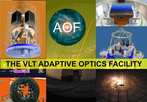
AOF<br />
<strong>THE</strong> <strong>VLT</strong> <strong>ADAPTIVE</strong> <strong>OPTICS</strong> <strong>FACILITY</strong>
SUMMARY:<br />
AOF Overview<br />
The DSM: the core of the AOF<br />
DSM Positioning System and<br />
AOF<br />
Manufacturing<br />
DSM Reference Body<br />
Mirror Unit manufacturing<br />
DSM Thin Shell<br />
TOPTICA-MPB 20 W Laser Concept<br />
Launch Telescope System<br />
GALACSI: AO Module for MUSE<br />
GALACSI Design<br />
MUSE Spectrograph<br />
GRAAL: GLAO Module for HAWK-I<br />
GRAAL Design and Performances<br />
GRAAL Assembly<br />
ASSIST: DSM Testbed<br />
ASSIST Design<br />
WFS Detectors and Electronics<br />
SPARTA: Standard Platform for Adaptive Optics Real Time Applications<br />
Milestones<br />
Organization Chart
AOF<br />
ASSIST<br />
AOF: <strong>ADAPTIVE</strong> <strong>OPTICS</strong> <strong>FACILITY</strong>:<br />
DSM: DEFORMABLE SECONDARY MIRROR<br />
4 LGSF: 4 LASER GUIDE STAR <strong>FACILITY</strong><br />
GALACSI: Ground Atmospheric Layer Adaptive Corrector for<br />
Spectroscopic Imaging<br />
MUSE: Multi-Unit Spectrocscopic Explorer<br />
GRAAL: GRound layer Adaptive optics Assisted by Lasers<br />
HAWK-I: High Acuity, Wide field K-band Imaging<br />
ASSIST: Adaptive Secondary Simulator and Instrument<br />
Testbed<br />
SPARTA: Standard Platform for Adaptive optics Real Time<br />
Applications<br />
GRAAL<br />
OVERVIEW<br />
DSM<br />
4LGSF<br />
GALACSI<br />
+<br />
MUSE
<strong>THE</strong> DSM: <strong>THE</strong> CORE OF AOF<br />
The coldplate<br />
plus<br />
the backplate.<br />
M2 unit is composed by an<br />
hexapod, a cold plate, a<br />
backplate and a thin shell<br />
mirror. The mirror positioning<br />
is obtained with an hexapod.<br />
The actuators are attached to<br />
a cold plate connected to a<br />
reference body, on which the<br />
thin shell is leaning when not<br />
operative.<br />
Hexapod for<br />
centering and<br />
fine focusing<br />
Cold Plate,<br />
heat<br />
evacuation<br />
and actuator<br />
attachment<br />
Reference<br />
body<br />
Thin Shell<br />
The thin shell mirror has a<br />
diameter of 1120 mm, 2 mm<br />
thickness, about 9 kg weight.<br />
1170 voice-coil actuators are<br />
acting on magnets glued on the<br />
back face of the shell (below:<br />
actuators pattern).
DSM POSITIONING<br />
SYSTEM<br />
MANUFACTURING<br />
HUB<br />
manufacturi<br />
ng on going.<br />
Complete<br />
verification,<br />
including full load<br />
test in the final<br />
configuration, of<br />
all the hexapods<br />
at ADS (May<br />
2011)<br />
Hexapod<br />
actuator<br />
prototype<br />
during<br />
functional<br />
test<br />
All the<br />
Hexapod after<br />
manufacturing<br />
and functional<br />
testing at<br />
ADS (March<br />
2011).
The magnets<br />
template<br />
manufacture<br />
d at ADS, for<br />
very<br />
accurate<br />
gluing of the<br />
magnets on<br />
the back<br />
face of the<br />
thin shell.<br />
The cold plate has<br />
been manufactured<br />
and metrologically<br />
checked with a<br />
computer controlled<br />
machine at ADS. It<br />
supports the 1170<br />
magnetic actuators,<br />
provides a heat sink<br />
for the heat dissipated<br />
on the actuators coils<br />
and makes a<br />
mechanical interface<br />
for the backplate..<br />
DSM BACKPLATE AND ACTUATORS<br />
Right: “mass”<br />
production of<br />
electronics<br />
and actuators<br />
at Microgate..<br />
Below: D-45 prototype<br />
test with and without<br />
thin shell: Electronics<br />
test, actuator coil test,<br />
capacitive sensor test.<br />
The thin shell is retained at its central hole by a dedicated titanium<br />
and steel bound (membrane), designed in order to prevent only<br />
lateral displacement, without affecting the magnetic actuator action.
Detail of<br />
the DSM<br />
ZERODUR<br />
light<br />
weighted<br />
reference<br />
body back<br />
side at the<br />
end of<br />
manufactur<br />
ing at<br />
S<strong>ESO</strong><br />
(August<br />
2010).<br />
The reference body at ADS, after<br />
silver coating and capacitive<br />
sensors etching (March 2011).<br />
The total weight of the<br />
component is 47 kg.<br />
Final inspection of the reference<br />
body at S<strong>ESO</strong>. The unit is ready<br />
for the metal coating deposition on<br />
the internal sides of the holes, for<br />
the capacitive sensor.<br />
REFERENCE<br />
BODY
The M2 Zerodur<br />
Test Matrix<br />
produced by<br />
REOSC for the<br />
<strong>VLT</strong>, inside the<br />
barrel (mount)<br />
manufactured for<br />
the M2 Test matrix<br />
by AOF. The test<br />
matrix is being<br />
inserted into the<br />
barrel with a<br />
custom designed<br />
and fabricated<br />
handling tool (April<br />
2007).<br />
DSM THIN SHELL<br />
Hextec slumped<br />
engineering shell,<br />
to be used for<br />
electromechal<br />
testing of the M2-<br />
DSM unit.<br />
Left: first thin science<br />
shell during the final<br />
phase of the convex side<br />
polishing at SAGEM<br />
(inspection, February<br />
2010). The Zerodur<br />
blank (Schott) grinding<br />
started in December<br />
2009. In February 2011<br />
the thickness was about<br />
2.8 mm.<br />
Right: The thin shell in<br />
February 2011 at<br />
SAGEM. In March<br />
2011 the goal<br />
thickness of 2 mm has<br />
been reached: it’s the<br />
first time in Europe for<br />
a curved shell.<br />
Hextec slumped engineering shell<br />
Schott blank for SAGEM (first science shell)
TOPTICA-MPB<br />
20 W LASER CONCEPT<br />
The TOPTICA-MPB design converts the infrared light generated by two<br />
coherently combined Raman Fibre Amplifiers into the yellow spectral region by<br />
Second Harmonic Generation (SHG): two 18 W beams at 1178 nm are<br />
combined with Coherent Beam Combination (CBC) for 20 W beam generation<br />
at 589 nm. With this approach more than 20W at 589 nm are achieved.<br />
1178 nm<br />
SEED<br />
LASER<br />
SHG output power 589nm, (W)<br />
25<br />
20<br />
15<br />
10<br />
5<br />
2×18 W POLARIZATION MAINTAINING<br />
RAMAN FIBER AMPLIFICATION MODULES<br />
COHERENT<br />
BEAM<br />
COMBINATION<br />
MODULE<br />
SECOND<br />
HARMONIC<br />
GENERATION<br />
589nm power vs. input 1178nm power<br />
in black: higher input coupler reflectivity<br />
in red: lower input coupler reflectivity<br />
0<br />
0 5 10 15 20 25 30 35<br />
1178nm input power, (W)<br />
589 nm<br />
output<br />
The laser designs is being<br />
developed by TOPTICA and<br />
MPB as part of the <strong>ESO</strong><br />
LGSF laser system.<br />
TOPTICA concept is based<br />
on Raman Fiber<br />
Amplification (RFAM).<br />
Left: plot of the output<br />
power @589 nm, as a<br />
function of the total RFAM<br />
power.<br />
The TOPTICA-<br />
MPB design<br />
source is very<br />
compact, and will<br />
be located next to<br />
the launching<br />
telescope ,<br />
without the need<br />
of a dedicated<br />
clean room.<br />
SHG prototype.<br />
Above: open top<br />
view. Below: 22.6 W<br />
output power @589<br />
nm have been<br />
demonstrated.
LAUNCH<br />
TELESCOPE<br />
SYSTEM<br />
Above: testing of<br />
coating samples at<br />
focus under high<br />
laser power<br />
illumination (March<br />
2010)<br />
The main OTA<br />
L2 during<br />
manufacturing at<br />
TNO (January<br />
2011). L2 is a 50<br />
mm thick, 300<br />
mm diameter<br />
aspherical lens.<br />
The LTS optical<br />
system is<br />
designed in order<br />
to expandt the 3<br />
mm diameter 589<br />
nm wavelength<br />
laser beam to a<br />
larger beam<br />
producing a laser<br />
spot of about 30<br />
cm at 90 km<br />
height. Four of<br />
these units will be<br />
mounted on the<br />
telescope azimutal<br />
platform, in order<br />
to create the 4<br />
LGS.<br />
Above, from left to right: scheme of the optical tube assembly;<br />
3-D model oone entire LTS, including Laser Head, Beam<br />
Control Diagnostic System (BCSD), Optical Tube Assembly,<br />
on its base plate; the LTS inside its enclosure; the four LTS<br />
units on the telescope.<br />
Below: the OTA structure at the end of<br />
manufacturing at TNO (January 2011).
GALACSI goal is to<br />
concentrate the energy of a<br />
Point Spread Function (PSF)<br />
over a large FoV (1’) for a<br />
visible-light integral field<br />
spectrograph (MUSE: Multi<br />
Unit Spectrographic Explorer),<br />
a second generation<br />
instrument for <strong>VLT</strong>.<br />
Here: 3-D model of GALACSI<br />
(left) on the Nasmyth platform<br />
with MUSE (right).<br />
Field of view 1’ WFM (7.5” NFM)<br />
Instrument Muse (VIS 3D‐spectrograph)<br />
Modes GLAO, LTAO<br />
Performance GLAO<br />
GALACSI: AO MODULE FOR MUSE<br />
GALACSI will operate in<br />
two modes: Wide Field<br />
Mode (WFM, seeing<br />
reducer over 1’ FoV at<br />
750 nm) and Narrow<br />
Field Mode (NFM, SR ≅<br />
6% at 650 nm, in 7.5”<br />
FoV). Here is shown a<br />
typical simulation of the<br />
PSF as expected with<br />
GALACSI in NFM.<br />
×2 in ensquared energy (central pixel),<br />
95% sky coverage<br />
Performance LTAO Strehl Ratio >5% @0.65µm<br />
WFS<br />
4 LGS L3‐CCD (1 e ‐ Read out Noise)<br />
1 TT L3‐CCD<br />
1 TT IR<br />
Loop frequency = 1 kHz<br />
SPARTA HW=GRAAL<br />
4LGSF<br />
4 stars ∅2’/∅20”<br />
LTAO drives LGS power<br />
ASSIST Full FoV<br />
Status FDR passed
GALACSI DESIGN<br />
Left: 3D GALACSI optical<br />
scheme, as view from<br />
MUSE.<br />
Left: 3-D optomechanical<br />
design of<br />
GALACSI: the LGS<br />
path module is<br />
shown in more detail<br />
enlarged above on<br />
the right.<br />
<strong>VLT</strong><br />
VISIBLE<br />
TIP-TILT<br />
PATH<br />
Above: the<br />
camera is the<br />
same as for<br />
GRAAL.<br />
Right: WFS<br />
detector and<br />
electronics.<br />
COMMISSIONING<br />
CAMERA PATH<br />
Pyramid optical beam splitting of the 4 laser<br />
guide stars onto the 4 WFS.<br />
LGS PATH 1<br />
MUSE<br />
CALIBRATION<br />
PATH<br />
LGS PATH 4<br />
LGS PATH 2<br />
LGS PATH 3
Above: GALACSI almost completely assembled,<br />
during testing at <strong>ESO</strong>.Except the LGS wavefront<br />
measuring path, GALACSI is already equipped<br />
with all the optics.<br />
Below: the the GALACSI support structure<br />
at <strong>ESO</strong> (March 2011) being alignmed.<br />
The light<br />
source<br />
module for<br />
the<br />
calibration.<br />
Above: the GALACSI Field Selector on a<br />
test setup: the Field Selector, source<br />
module, Lamp housing/fibre injection and<br />
motor controllers are in use.<br />
GALACSI GROWTH
MUSESPECTROGRAPH<br />
MUSE visible integral field spectrograph splits the GALACSI adaptive optics<br />
corrected field of view in 24 sub-fields. Each of these sub-fields is fed into a<br />
spectrograph (Integral Field Unit, IFU). An image slicer in front of each IFU<br />
serves as entrance slit, thus producing a spatially resolved spectrum of the<br />
full sub-field.<br />
MUSE features a Wide Field Mode (WFM) with a 1×1 arcmin field of view<br />
and a Narrow Field Mode (NFM) with a 7.5×7.5 arcsec field of view,<br />
providing simultaneous spectra of numerous adjacent regions in the sky.<br />
A fore-optics tower between the telescope focus and the IFUs hosts a field<br />
de-rotator, an ADC, the shutter, the field splitting optics and a plate scale<br />
changer. A calibration unit is close to the telescope focus.<br />
MUSE total weight is more than 7 tons.<br />
Above: the first of the 3D spectrographs, ready after extensive<br />
testing at the CRAL optical laboratory.<br />
Left: the large MUSE cryogenic system which provides cooling<br />
and vacuum for the 24 MUSE detectors (-130° C ), in the<br />
integration and test phase at <strong>ESO</strong><br />
Above: one of the 24 16-million pixel detectors to be used) in<br />
MUSE. MUSE combines 24 spectrographs (460-930 nm<br />
wavelength) in order to be able to probe a field of view as large as<br />
possible.<br />
Left: an image slicer, composed of two optical elements: the image<br />
dissector array (in front) is made of 48 thin (0.9 mm) off-axis<br />
spherical mirrors and the focusing mirror array is made of 48 round<br />
off-axis spherical mirrors. Image slicers, a new technology,<br />
maintain high optical efficiency, and MUSE is using the largest<br />
image slicers ever used in astronomy. Each spectrograph is<br />
equipped with 4000 x 4000 pixel detectors — the largest detectors<br />
used at <strong>ESO</strong> so far.
GRAAL SPACE<br />
ENVELOPE<br />
LGS trombone<br />
LGS WFS assembly<br />
NGS‐TT sensor<br />
assembly<br />
Steel flange<br />
Torque drive<br />
Cable guide<br />
system<br />
HAWK-I FoV NASMYTH INTERFACE FLANGE<br />
Bearing<br />
Main structure<br />
Steel<br />
structure<br />
HAWK-I<br />
A view cut through the median plane of the AO system shows the limited<br />
available space.<br />
Exploded view of GRAAL mechanical structure: the bearing is designed for<br />
150Nm friction/80kg, the torque drive for 500Nm nominal/70kg. The cableguide<br />
system weight is 110 kg, the aluminium structure 75 kg and the steel<br />
structure 50 kg. GRAAL total weight is 950 kg (about 2900 kg with HAWK-I).<br />
Counterweight<br />
Maintenance and<br />
Commissioning<br />
assembly<br />
Hawk‐I shutter<br />
Elect. box Elect. box<br />
GRAAL is a seeing<br />
improver ground layer<br />
adaptive optics<br />
system, assisted by 4<br />
LGS, with science<br />
FoV is of 7.5” square,<br />
for feeding the<br />
cryogenic NIR imager<br />
HAWK-I.<br />
Open view<br />
of GRAAL<br />
with the<br />
HAWK-I<br />
adapter.<br />
GRAAL with HAWK-I on the Nasmyth<br />
platform. Hawk-I is an already existing NIR<br />
wide field imager (7.5’×7.5’ FoV).<br />
GRAAL is compact: in the simulation<br />
picture of the Nasmyth platform (on the<br />
right), the volume attached to the<br />
telescope adapter-rotator remains nearly<br />
the same as before GRAAL installation.<br />
GRAAL is tinted in red and yellow, and is<br />
in its integration configuration. One<br />
electronics cabinet (not represented) lies<br />
on the Nasmyth platform, another one on<br />
the azimuth platform.<br />
GRAAL: GLAO<br />
MODULE FOR<br />
HAWK-I
<strong>VLT</strong><br />
The complexity of the optical design relies in the tight<br />
arrangement of GRAAL optics in the space available between<br />
the telescope adapter and Hawk-I, requiring some optics to be<br />
located in a complex 3-D geometry. S<strong>ESO</strong> started the<br />
manufacturing of the optics in June ’09.<br />
Field of view 7.5’ (10” MCM)<br />
instrument Hawk‐I (IR imager)<br />
modes GLAO, SCAO<br />
Performance GLAO x1.7 (central pixel), 95% sky coverage<br />
Performance SCAO (80% in K‐band)<br />
WFS<br />
LASER<br />
PATH<br />
MAINTENANCE<br />
AND<br />
COMMISSIONING<br />
PATH<br />
HAWK-I<br />
TIP-TILT<br />
CORRECTION<br />
PATH<br />
4 LGS L3‐CCD (1 e ‐ Read out Noise)<br />
1 TT L3‐CCD<br />
1 NGS L3‐CCD<br />
Loop frequency ≥ 700 Hz<br />
SPARTA HW=GALACSI<br />
4LGSF 4 stars Ø12’/‐<br />
ASSIST Limited FoV<br />
Status<br />
Detailed design, sub‐contracted main<br />
assembly<br />
GRAAL main<br />
assembly<br />
descriptive view.<br />
The main<br />
assembly has<br />
been designed<br />
as a plug-andplay<br />
unit: no<br />
modification of<br />
any Hawk-I<br />
internal part is<br />
necessary during<br />
the installation.<br />
The design<br />
concept has<br />
been developed<br />
at <strong>ESO</strong>.<br />
GRAAL DESIGN AND PERFORMANCES<br />
GRAAL is<br />
expected to<br />
provide about a<br />
factor 2 of<br />
improvement in<br />
the occurrence<br />
of good images<br />
(
Above and below: tests of the optics at S<strong>ESO</strong><br />
Below: one of the LGS pick-up arm mounted on<br />
its Physik-Instrumente translator, installed<br />
inside the GRAAL rotating flange at NTE..<br />
GRAAL FINAL<br />
TESTS …<br />
Left: WFS<br />
assembling<br />
Left:<br />
cooling<br />
system;<br />
right with<br />
electronics.<br />
Above: from bottom left, clockwise:<br />
TT unit, LGS calibration assembly,<br />
MCM lens (February 2011).<br />
Below: during assembly of the the rotating<br />
frame at NTE (September 2010)
Above: GALACSI (front) and GRAAL (back) in<br />
the <strong>ESO</strong>-Garching integration hall.<br />
Below: GRAAL mechanical structure fully<br />
integrated. The optics are missing.<br />
GRAAL mechanical structure has been assembled in the<br />
<strong>ESO</strong>-Garching integration hall in June 2011. The<br />
mechanics is already mounted and working, and optics are<br />
ready for integration. GRAAL will be the first instrument to<br />
be tested on ASSIST. GRAAL tests at <strong>ESO</strong> will last until<br />
end of 2012.<br />
… AND NOW AT<br />
<strong>ESO</strong><br />
Above: enlargement of the central part of<br />
GRAAL mechanical structure, front view.<br />
Below: the same part, view from the rear<br />
side during a special progress meeting
3-D view of<br />
ASSIST<br />
assembly<br />
without the<br />
cover, with the<br />
DSM module<br />
and GALACSI<br />
separated from<br />
the adapter.<br />
The external<br />
dimensions are<br />
about 4.5 m×4<br />
m×3.5 m.<br />
ASSIST: DSM TEST BED<br />
DSM<br />
AM2<br />
AM1<br />
ADAPTER<br />
GALACSI<br />
ASSIST IS <strong>THE</strong> OPTICAL <strong>FACILITY</strong> DESIGNED FOR TESTING<br />
AND CHARACTERISING <strong>THE</strong> DSM, TOGE<strong>THE</strong>R WITH GRAAL<br />
AND GALACSI, BEFORE INSTALLATION AT PARANAL. IT WILL<br />
BE FIRST INSTALLED AT GARCHING AND <strong>THE</strong>N SENT TO<br />
PARANAL TO AID <strong>THE</strong> DSM INSTALLATION.<br />
ASSIST optical design: AM1 and AM2: ASSIST mirrors; DSM: Deformable<br />
Secondary Mirror; FM: Folding mirror; SSTG: Star Simulator Turbulent<br />
Generator; VFS: <strong>VLT</strong> Focus Simulator. The NGS and LGS (GALACSI and<br />
GRAAL) sources are simulated by the Source Injection module.
AM1 spherical<br />
polishing<br />
started at end<br />
of September<br />
2009. Left:<br />
carefully<br />
checking the<br />
mirror after<br />
final aspherical<br />
polishing at<br />
AMOS<br />
(February<br />
2011).<br />
ASSIST AM1 PRIMARY MIRROR<br />
Above: microscopic measurement of the rougness.<br />
Rgiht: the final testing of AM1 surface implies a<br />
complex interferometric setup including a<br />
Computer Generated Hologram mask for taking<br />
care of its aspherical shape.<br />
The final specifications on the whole AM1 surface<br />
are less than 300 nm RMS on the whole useful<br />
diameter (1650 mm), up to less than 10 nm RMS for<br />
spatial scales smaller than 100 mm.<br />
AM1, an<br />
aspherical f/1<br />
mirror, with1.7 m,<br />
diameter, made<br />
of Zerodur, is the<br />
most critical<br />
component of<br />
ASSIST.<br />
On the left: AM1<br />
is in the coating<br />
chamber at Calar<br />
Alto Observatory<br />
(April 2011), after<br />
final protected<br />
aluminum<br />
coating.<br />
SPECS<br />
MEASURED
Left: AM2<br />
polishing and<br />
testing at NOVA<br />
optical<br />
laboratory at<br />
ASTRON (June<br />
2010): AM2 is<br />
an aspherical,<br />
140 mm<br />
diameter mirror,<br />
which surface<br />
quality is very<br />
critical for<br />
allowing GRAAL<br />
and GALACSI<br />
testing with<br />
ASSIST.<br />
Right: the<br />
LGS sources<br />
of ASSIST.<br />
Left: the<br />
external<br />
modules during<br />
final testing at<br />
Winlight:<br />
clockwise, from<br />
upper left: the<br />
frong group,<br />
FM4, the source<br />
group, VL12.<br />
Right: one of<br />
the first Phase<br />
Screens<br />
produced by<br />
SILIOS: the<br />
phase map is<br />
visible in<br />
transparence<br />
on the glass.<br />
Above: full assembling of the ASSIST main structure<br />
mechanics at Boseenkool (NL) (February 2011). Left: the<br />
tower before enclosure. Right: with enclosure. On top of the<br />
tower the dummy loads simulating the DSM weight are visible.<br />
ASSIST MANUFACTURING<br />
Below: the frame allowing Phase Screen exchange and<br />
rotation. This is part of the Star Simulator and Turbulence<br />
Generator module (SSTG). The Phase Screens allow to<br />
simulate a seeing and turbulence profile including coherence.
AM1 in its<br />
cell and<br />
FM1<br />
spider<br />
Right:<br />
alignment<br />
of the<br />
optics<br />
with the<br />
site<br />
telescope<br />
Left:<br />
mechanical<br />
structure<br />
assembling<br />
Right: the<br />
whole<br />
structure<br />
assembled<br />
(June<br />
2011):<br />
DSM<br />
tower,<br />
Shack-<br />
Hartmann<br />
tower and<br />
adaptor<br />
ring. The<br />
total height<br />
is more<br />
than 5 m.<br />
Left: 400<br />
kg AM1<br />
handling<br />
AM2 in its<br />
spider<br />
Center<br />
right:<br />
internal<br />
view from<br />
the top<br />
ASSIST INTEGRATION AT <strong>ESO</strong> Right:<br />
Right:<br />
centered<br />
reflected<br />
rings from<br />
AM2
CCD 220:<br />
240×240<br />
pixels,<br />
standard<br />
silicon<br />
8 EM<br />
amplified<br />
outputs up to<br />
15 Mpix/sec,<br />
1400<br />
frames/sec.<br />
Analog Front-End<br />
Boards<br />
The WFS camera is very compact<br />
168×240×75 mm. Weight: 3.5kg<br />
Digital Control<br />
Electronics Boards<br />
OCam Test<br />
Camera<br />
part of<br />
Opticon<br />
ELECTRONICS<br />
JRA2 FP6<br />
technology<br />
transfer WFS DETECTORS<br />
expected<br />
soon<br />
duplications<br />
for <strong>ESO</strong> and<br />
and<br />
Grantecan.<br />
WFS camera with OCAM clock board, Hermetic<br />
connectors (power entry, Peltier control, temperature<br />
sensing, alarms), Fiber interface (4 duplex links, 3.125<br />
Gb/s per link = 12 Gb/s, Connection to NGC back-end,<br />
Connection to RTC), cooling system prototype (pressure<br />
level of 20 bar)<br />
CCD 220 thermal model with heat sink design: cryogenic<br />
tests are satisfactory (up to required -45°C). Water pipes<br />
used for cooling are located on two opposite sides of the<br />
heat sink. Heat sink is meshed here in dark blue, water is<br />
meshed in blue.
User and Engineering Interface<br />
Real Time Data Display<br />
Standard hardware<br />
Rich test tool suite<br />
Full <strong>VLT</strong> SW compatible via gateways<br />
SPARTA<br />
GB Ethernet Switch<br />
Co-processing cluster<br />
RTC box<br />
High End Intel CPU / Multi-core / Multi-<br />
CPU, Linux based<br />
Industry standard libraries and<br />
middleware, commercial (40kE) and<br />
open source (CORBA/DDS)<br />
Modular, scalable, fully reusable<br />
Standard Platform for<br />
Adaptive optics Real Time<br />
Applications<br />
RTC box (~200k€/system):<br />
hard real-time system to drive the AO<br />
control loops; can receive data from<br />
multiple sensors (4+1 for AOF) and can<br />
control multiple mirrors (1+4 for AOF) at<br />
high speed (1 KHz for AOF) with<br />
extremely low jitter and very low latency.<br />
Fully software reconfigurable to support<br />
multiple applications (GRAAL HAWK-I<br />
and GCM).<br />
High-tech crate, fully EMI tested, active<br />
protection.<br />
Supervisor (~20k€/system):<br />
High-througput, high-performance,<br />
parallel soft real-time system. Controls<br />
the real-time box, implements the AO<br />
“business logic”, handles<br />
computational intensive tasks like<br />
performance estimation, loop<br />
optimization, atmospheric statistics,<br />
calibration.<br />
SUPERVISOR<br />
REAL-TIME BOX<br />
SPARTA is a highly scalable hardware and software platform for adaptive optics<br />
real-time computers providing very low latency together with high throughput. All 2 nd<br />
generation AO instruments (including GRAAL and GALACSI) will be equipped with a<br />
SPARTA RTC system.<br />
Multi-technology Real-Time Box: DSP + FPGA + CPU<br />
Very low total latency (
MILESTONES<br />
ASSIST<br />
CDR PDR FDR ARR FAT PAE PAC<br />
Oct.07 30.06.09 2Q11 3Q11 2Q12<br />
DSM 18.12.07 24.09.09 Apr.’11 4Q12<br />
GRAAL Sept.’05<br />
KO<br />
Mar.07 10.03.09 2Q11 4Q12 2Q13<br />
GALACSI Feb.’06 Feb.08 10.02.09 16.06.09 2Q11 2Q13 4Q13<br />
4LGSF 30.09.09 3.02.11 2Q11 N/A 2Q13<br />
AOF Sys. 24.04.08 29.04.10 N/A<br />
4Q11<br />
(TRR)<br />
UT4 Upg. 29.04.10 N/A 2Q11 N/A N/A<br />
4Q13<br />
1Q12<br />
PhaseI<br />
4Q14<br />
3Q12<br />
PhaseII<br />
MUSE Dec.07 Mar.09 N/A 2Q12 (2Q13)<br />
SPARTA Jun.07 Sept. 08 N/A<br />
2Q11<br />
(SPHERE)<br />
4Q13<br />
(GALACSI)<br />
N/A
ORGANIZATION CHART<br />
Programme Office<br />
(Head)<br />
Project Control 1 : J.<br />
Strasser<br />
Quality: G. Igl<br />
Analysis<br />
System Engineer<br />
P.-Y. Madec<br />
Simulations<br />
M. Le Louarn<br />
Interfaces<br />
P.-Y. Madec<br />
System Tests &<br />
Calibrations<br />
J. Kolb<br />
ASSIST Test<br />
Bench Agreement<br />
P. LaPenna<br />
AOF AIT<br />
S. Tordo<br />
Safety<br />
P.-Y. Madec<br />
Project Control 2<br />
L. Jochum<br />
GALACSI<br />
Manager<br />
S. Stroebele<br />
Inst. Control<br />
M. Duchateau<br />
Optics<br />
B. Delabre<br />
Mechanics<br />
R. Conzelmann<br />
Software (OS)<br />
M. Kiekebusch<br />
Software/RTC<br />
C. Soenke<br />
AIT<br />
S. Tordo<br />
Project Scientist<br />
H. Kuntschner<br />
Project Manager<br />
R. Arsenault<br />
GRAAL Manager<br />
J. Paufique<br />
Inst. Control<br />
A. Jost<br />
Optics<br />
B. Delabre<br />
Mechanics<br />
R. Conzelmann<br />
GMA Contract<br />
J. Paufique<br />
Software (OS)<br />
M. Kiekebusch<br />
Software/RTC<br />
R. Donaldson<br />
AIT<br />
S. Tordo<br />
System Eng.<br />
P.-Y. Madec<br />
4LGSF Manager<br />
W. Hackenberg<br />
System Eng.<br />
D. Bonaccini-<br />
Calia<br />
Inst. Control<br />
I. Guidolin<br />
Mechanics<br />
R. Guzman<br />
Software<br />
M. Comin<br />
Opt. Tube<br />
Assembly Contract<br />
M. Quattri<br />
Lasers Contract<br />
P.-Y. Madec<br />
AIT<br />
C. Dupuy<br />
Directorate –A. Russell<br />
Div. Head –M. Casali<br />
Steering Committee<br />
M.Casali, R.Tamai, S.Stanghellini,<br />
U.Weilenman, L.Pasquini, N.Hubin<br />
UT4 Upgrade<br />
Manager<br />
J.-F. Pirard<br />
UT4<br />
Implementaion<br />
J.-F. Pirard<br />
Comm.<br />
J.-F. Pirard<br />
2 nd Gen. M2-<br />
Unit Manager<br />
E. Vernet<br />
2 nd Gen. M2-Unit<br />
Contract<br />
E.Vernet<br />
M2-LCU<br />
P. Duhoux<br />
DSM Maint. SW<br />
P. Duhoux<br />
1 Finance control<br />
2 Project planning control
Optical Infrared Coordination Network for Astronomy<br />
http://www.astro-opticon.org/<br />
Nederlandse Organisatie voor Toegepast Natuurwetenschappelijk Onderzoek<br />
http://www.tno.nl/<br />
Nederlandse Onderzoekschool voor de Astronomie<br />
http://www.strw.leidenuniv.nl/nova/<br />
Istituto Nazionale di Astrofisica<br />
http://www.inaf.it/<br />
Sterrewacht Leiden<br />
http://www.strw.leidenuniv.nl/<br />
Advanced Mechanical and Optical Systems<br />
http://www.amos.be/<br />
Laboratoire d’Astrophysique de Marseille<br />
http://www.oamp.fr/infoglueDeliverLive/www/+LAM<br />
FASORtronics<br />
http://www.fasortronics.com/FASORtronics/FASORtronics_LLC.html<br />
Societé Européenne de Systèmes Optiques<br />
http://www.seso.com/uk/<br />
Sagem<br />
http://sagem-ds.com/<br />
MUSE consortium<br />
http://muse.univ-lyon1.fr/http://sagem-ds.com/<br />
Hextec<br />
http://www.hextek.com/<br />
ADS International<br />
http://www.ads-int.com/<br />
Microgate Engineering<br />
http://www.microgate.it/engineering/default.asp<br />
Schott<br />
http://www.schott.com/<br />
Winlight Optical System<br />
http://www.winlight-system.com/<br />
SILIOS Technologies<br />
http://www.silios.com/<br />
Array Electronics<br />
http://www.array-electronics.com/<br />
e2v<br />
http://www.e2v.com/<br />
NTE<br />
http://www.nte.es/<br />
Toptica Photonics<br />
http://www.toptica.com/<br />
MPB Communications Inc.<br />
http://www.mpbc.ca/<br />
<strong>ESO</strong><br />
European Organisation<br />
for Astronomical<br />
Research in the<br />
Southern Hemisphere<br />
AOF Industrial Contractors & Partners<br />
Calar Alto Observatory<br />
http://www.caha.es/<br />
Machinenfabriek Boessenkoo bv<br />
http://www.boessenkool.com/<br />
JDSU<br />
http://www.jdsu.com/en-us/Pages/Home.aspx<br />
Precision Optics Gera<br />
http://www.pog.eu/en/products_os_00.html<br />
SUSS MicroTec<br />
http://www.suss.com/<br />
mso jena Mikroschichtoptik GmbH<br />
http://www.suss.com/<br />
Physik Instrumente Piezo nano positioning<br />
http://www.physikinstrumente.de/de/index.php
<strong>ESO</strong><br />
European Organisation<br />
for Astronomical<br />
Research in the<br />
Southern Hemisphere<br />
P. Amico, R. Arsenault, D. Bonaccini-Calia, B. Buzzoni, M. Comin, R. Conzelmann, B. Delabre, R. Donaldson, M. Duchateau, P. Duhoux, C. Dupuy, E. Fedrigo, I. Guidolin,<br />
R. Guzman Collazos, W. Hackenberg, G. Hess, N. Hubin, L. Jochum, P. Jolley, A. Jost, P. Jolley, L. Kern, M. Kiekebusch, J. Kolb, H. Kuntschner, P. La Penna, M. Le Louarn, J.-L. Lizon,<br />
P.-Y. Madec, A. Manescau, J. Paufique, J.-F. Pirard, M. Quattri, J. Quentin, C. Soenke, S. Stroebele, S. Tordo, E. Vernet<br />
Preparation & Editing: P. La Penna, <strong>ESO</strong>