SSonde_Cat_rev201003.. - CODAR Ocean Sensors
SSonde_Cat_rev201003.. - CODAR Ocean Sensors
SSonde_Cat_rev201003.. - CODAR Ocean Sensors

Create successful ePaper yourself
Turn your PDF publications into a flip-book with our unique Google optimized e-Paper software.
Continuous<br />
Surface Current Mapping<br />
& Wave Monitoring<br />
System<br />
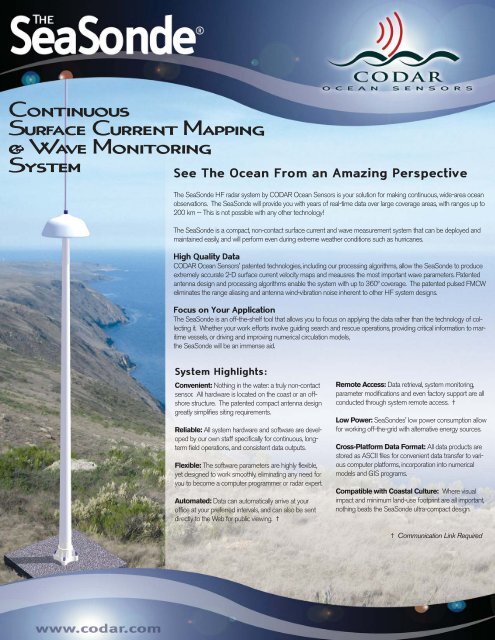
See The <strong>Ocean</strong> From an Amazing Perspective<br />
The SeaSonde HF radar system by <strong>CODAR</strong> <strong>Ocean</strong> <strong>Sensors</strong> is your solution for making continuous, wide-area ocean<br />
observations. The SeaSonde will provide you with years of real-time data over large coverage areas, with ranges up to<br />
200 km -- This is not possible with any other technology!<br />
The SeaSonde is a compact, non-contact surface current and wave measurement system that can be deployed and<br />
maintained easily, and will perform even during extreme weather conditions such as hurricanes.<br />
High Quality Data<br />
<strong>CODAR</strong> <strong>Ocean</strong> <strong>Sensors</strong>' patented technologies, including our processing algorithms, allow the SeaSonde to produce<br />
extremely accurate 2-D surface current velocity maps and meausres the most important wave parameters. Patented<br />
antenna design and processing algorithms enable the system with up to 360º coverage. The patented pulsed FMCW<br />
eliminates the range aliasing and antenna wind-vibration noise inherent to other HF system designs.<br />
Focus on Your Application<br />
The SeaSonde is an off-the-shelf tool that allows you to focus on applying the data rather than the technology of collecting<br />
it. Whether your work efforts involve guiding search and rescue operations, providing critical information to maritime<br />
vessels, or driving and improving numerical circulation models,<br />
the SeaSonde will be an immense aid.<br />
System Highlights:<br />
Convenient: Nothing in the water: a truly non-contact<br />
sensor. All hardware is located on the coast or an offshore<br />
structure. The patented compact antenna design<br />
greatly simplifies siting requirements.<br />
Reliable: All system hardware and software are developed<br />
by our own staff specifically for continuous, longterm<br />
field operations, and consistent data outputs.<br />
Flexible: The software parameters are highly flexible,<br />
yet designed to work smoothly, eliminating any need for<br />
you to become a computer programmer or radar expert.<br />
Automated: Data can automatically arrive at your<br />
office at your preferred intervals, and can also be sent<br />
directly to the Web for public viewing. †<br />
Remote Access: Data retrieval, system monitoring,<br />
parameter modifications and even factory support are all<br />
conducted through system remote access. †<br />
Low Power: SeaSondes' low power consumption allow<br />
for working off-the-grid with alternative energy sources.<br />
Cross-Platform Data Format: All data products are<br />
stored as ASCII files for convenient data transfer to various<br />
computer platforms, incorporation into numerical<br />
models and GIS programs.<br />
Compatible with Coastal Culture: Where visual<br />
impact and minimum land-use footprint are all important,<br />
nothing beats the SeaSonde ultra-compact design.<br />
† Communication Link Required
SeaSonde Configuration: Standard Hi-Res Long-Range<br />
Spatial Range (typical)<br />
Alongshore: 20-60 km 15-30 km 100-220 km<br />
Offshore: 20-75 km 15-20 km 140-220 km<br />
• Ranges achieved vary with environmental conditions and antenna placement. Note: Two radars are normally required for creating<br />
2-D surface current maps of direction and speed.<br />
Range Resolution 500 m - 3 km 200-500 m 3-12 km<br />
• Resolution is user selectable.<br />
Angular Resolution: 1-5 degree grid: user selectable.<br />
Current Accuracy: Varies with environment. Comparisons with ADCPs located in close proximity to the surface are typically<br />
< 7 cm/s of the total current velocity and 1-2 cm/s of the tidal component.<br />
Wavefield Products (measured at each radar): Local on-shore wave conditions in ring centered ~3 km from coast around<br />
each radar. Significant Waveheight: typical accuracy: 7-15%; Dominant On-Shore Direction: typical accuracy: 5 degrees -12<br />
degrees; Dominant Wave Period: typical accuracy: 0.6 s; Other spectral wave parameters available. Wave information is limited<br />
by environmental conditions and operating frequency.<br />
Frequency Range (antennae tuned to operate at a frequency subband within):<br />
Standard Hi-Res Long-Range<br />
one of either: one of either: 4.3-5.4 MHz<br />
11.5-14 MHz or 24-27 MHz or<br />
24-27 MHz 40-45 MHz<br />
• Patented technology permits the simultaneous operation of multiple radars on a single frequency, thereby minimizing frequency<br />
requirements and interference.<br />
• Operators must adhere to their country’s radio communications regulations regarding radiated signal specifications, and receive<br />
proper authorizations prior to operation. Consult company.<br />
Equipment Dimensions:<br />
Transmit Antenna Height: 4.8 m for 11-14 MHz Combined with RX 9 m<br />
Transmit Antenna Post 4 m N/A N/A<br />
Receive Antenna System (mast, dome loopstick antenna unit & vertical element atop dome) approx. total height 7m<br />
Receive Chassis: 13H x 49W x 53D cm. Weight:14 kg<br />
Transmit Chassis: 13H x 49W x 53D cm. Weight:15 kg<br />
Maximum Distance Between Adjacent Radars: Recommend 40-60% of the radar's offshore range.<br />
Power Requirements:<br />
Either 120 VAC or 220 VAC, 50-60 Hz; total onsite electronics varies between 350<br />
and 500 watts depending upon peripherals desired. [24 volt DC versions also available]<br />
Output Radiated Power: 80 watts peak, 40 watts average<br />
† For complete system specifications, please consult Technical Specification sheets available on company website.<br />
SeaSonde data integrated<br />
into Google-based interface<br />
created by Scripps Institute of<br />
<strong>Ocean</strong>ography (SIO).<br />
Data courtesy of SIO.<br />
Receive<br />
Antenna<br />
Courtesy of D. Musgrave,<br />
U. Alaska Fairbanks<br />
Transmit<br />
Antenna<br />
SeaSonde Electronics<br />
About <strong>CODAR</strong><br />
<strong>CODAR</strong> <strong>Ocean</strong> <strong>Sensors</strong> personnel<br />
are the inventors and<br />
original developers of HF and<br />
VHF radar technology for<br />
ocean monitoring applications,<br />
some having been in this field<br />
for nearly 40 years. <strong>CODAR</strong><br />
staff continue to make<br />
advancements in radar physics<br />
theory as well as product<br />
engineering refinements, and<br />
apply them to ensure the<br />
SeaSonde as the most reliable<br />
HF radar system in the world.<br />
The RiverSonde is their latest<br />
product to enter the market,<br />
and takes advantage of many<br />
key SeaSonde features.<br />
Headquarters:<br />
1914 Plymouth Street<br />
Mountain View, CA 94043 USA<br />
Phone: +1 (408) 773-8240<br />
Fax: +1 (408) 773-0514<br />
Toronga, 31 Madrid, ES-28043<br />
SPAIN<br />
Phone: +34 911263423<br />
Fax: +34 911263424<br />
email: info@codar.com<br />
Web: www.codar.com<br />
VER-20100331
<strong>CODAR</strong> OCEAN SENSORS SeaSonde® Remote Unit System Specifications<br />
Product Code: SSRS-100<br />
SeaSonde Remote Unit Components†<br />
• 1 Transmit Antenna Assembly (SSTA) & 1 Receiver Antenna Assembly (SSRA) OR,<br />
! 1 Combined Transmit-Receive Antenna Assembly (SSTR) (avail. for frequencies 11.5 MHz and higher)<br />
• 1 Transmit Cable & 1 Receive Antenna Cable Set OR,<br />
! 1 Combined Transmit-Receive Antenna Cable Set (avail. for frequencies 11.5 MHz and higher)<br />
• 1 SeaSonde Receiver Chassis (SSRX)<br />
• 1 SeaSonde Transmitter Chassis (SSTX)<br />
• 1 Radial Site Data Acquisition System (SSDA 100)<br />
• 1 Electronics Interconnector Cable Kit<br />
• 1 Set Operator Instruction Manuals, PDF format<br />
• One Year Manufacturerʼs Warranty<br />
Technical Specifications<br />
RADIATED SIGNAL SPECIFICATIONS<br />
Operators must adhere to local radiated signal regulations<br />
and receive proper authorizations prior to operation.<br />
Output Radiated Power: 80 W peak, 40 W average<br />
Operating Frequency Range:<br />
! Electronics: 4.4 – 50 MHz<br />
! Antennas: Select from one of either:<br />
! 4.4-6 MHz or<br />
! 11.5 - 14 MHz or<br />
! 24-27 MHz or<br />
! 40-45 MHz or<br />
! custom: any other frequency between 4.4-50 MHz<br />
Modulation Format: Pulsed Swept Frequency CW<br />
Sweep Width: 12-300 kHz (typical)<br />
Pulse Repetition Frequency: 514 - 8224 Hz<br />
Sweep Repetition Frequency: 1-4 Hz<br />
Total Radiated Signal Bandwidth: (at -20dB level) 65-200<br />
kHz<br />
Polarization: Vertical<br />
System Power Requirement (transmitter, receiver &<br />
computer): 350 watts (24V DC ver.) or 500 watts (120-220<br />
VAC)<br />
TRANSMITTER<br />
† Base components only: review Remote Unit<br />
Configuration Options inside this specification sheet.<br />
Transmitter Chassis: SSTX<br />
Input RF Drive Level: 0 dBm<br />
Output RF Power Level: 100 watts peak, 50 watts average<br />
Power Requirements: 300 watts;<br />
! (select one when ordering):<br />
120 V AC, 50-60 Hz<br />
220 V AC, 50-60 Hz<br />
24 V DC<br />
Design: (gated FET) modular; solid state<br />
Operation: Class AB<br />
Dimensions: (single chassis) 19” rack mountable, 3U tall;<br />
13H x 49W x 53D (cm)<br />
Weight: 15 kg<br />
Temperature Range (ambient): 0˚ F (-18˚ C) to 90˚F (32˚ C)<br />
Maximum Humidity: 80% non-condensing<br />
SSRS-100 specification, v4, rev 03/2010<br />
Receive Antenna (SSRA)<br />
or<br />
Combined Transmit-Receive<br />
Antenna (SSTR)<br />
SSDA 100<br />
RECEIVER<br />
SSTX<br />
SSRX<br />
(SSTA)<br />
Receiver Chassis: SSRX<br />
Maximum In-band Input Level: 0 dBm<br />
Receiver Channel Impedance: 50 ohm<br />
Sensitivity (noise level): -166 dBm in 1 Hz BW<br />
Power Requirements: 100 watts;<br />
! (select one when ordering):<br />
120 V AC, 50-60 Hz<br />
220 V AC, 50-60 Hz<br />
24 V DC<br />
Design: modular, solid state, three-channel<br />
Operation: I/Q homodyne<br />
Output: USB digital output; digital data at 4096 16-bit/<br />
second per channel<br />
Dimensions: (single chassis) 19” rack mountable, 3U tall;<br />
13H x 49W x 53D (cm)<br />
Weight: 14 kg<br />
[ Optional “SHARE” GPS synchronization Feature: GPS<br />
assisted stability: >.0001 ppm and 50 nsec on PPS ]<br />
Temperature Range (ambient): 0˚ F (-18˚ C) to 90˚F (32˚ C)<br />
Maximum Humidity: 80% non-condensing<br />
System Requirement: AC Power Conditioning via<br />
Uninterruptable Power Supply (UPS). Minimum<br />
recommended UPS capacity: 1500 VA (1050 Watt)
ANTENNA CABLING<br />
Requirement- Cabling Protection:<br />
Ideally cables between antennas and electronics are fed through protective conduit (such as 3.5 cm diameter PVC pipe) and<br />
buried in trench. There are lower cost options available, but there will be greater risk to exposure and damage.<br />
Transmit Cable<br />
Type: Single Strand RG-8 Low loss Co-Ax, 75 m length<br />
Receive Cable Set<br />
Type: Quad strand RG-58 Low loss Co-Ax bundle, 100m<br />
length<br />
ANTENNA ASSEMBLY<br />
Note: Antennas for operation at one frequency band and bandpass filters for operation at two frequency bands are included with<br />
SeaSonde remote unit purchase. Antennas and filters for operation at additional frequency bands can be purchased separately.<br />
Requirement- Bases/Mountings for Antennas:<br />
Antennas need to be mounted vertically secured to concrete concrete pad (~ 1m x 1m 1m) or lashed/guyed to fencing or other<br />
solid structure. Read SeaSonde Antenna Installation User's Guide for examples.<br />
Receive Antenna Assembly<br />
Consists of:<br />
! mast,<br />
! dome loopstick antenna unit &<br />
! vertical element (set atop dome)<br />
Durability: All-weather<br />
Total antenna height:<br />
! 4.3 - 5.4 MHz: approx. 6.5 m<br />
! 11.5- 14 MHz: approx. 6.5 m<br />
Design: passive vertical monopole, two crossed loops into<br />
preamplifiers<br />
Functionality: omnidirectional, adjustable (in software) from<br />
1-360 degrees<br />
Transmit Antenna<br />
Durability: All-weather<br />
Total height:<br />
! 4.4- 5.3 MHz: approx. 8.6 m<br />
! 11.5-14 MHz: approx. 8.6 m<br />
Transmitting Design: vertical monopole; omnidirectional<br />
SSRS-100 specification, v4, rev 03/2010<br />
Combined Transmit- Receive Cable Set<br />
(for 11.5 MHz and higher frequency bands)<br />
Type: 1 x RG-8 + 2 x RG-58 Low-loss Co-Ax bundle,<br />
Length: 75m (optional custom lengths available)<br />
Combined Transmit-Receive Antenna Assembly<br />
(for 11.5 MHz and higher frequency bands)<br />
Consists of:<br />
! mast,<br />
! dome loopstick antenna unit &<br />
! vertical element (set atop dome)<br />
Durability: All-weather<br />
Total antenna height:<br />
! 11.5- 14 MHz: approx. 8 m<br />
! 24-27 MHz: approx. 6.5 m<br />
! 40-45 MHz: approx. 5.5 m<br />
Receiving Design:<br />
! passive vertical monopole, two crossed loops into<br />
preamplifiers<br />
! omnidirectional, adjustable from 1-360 degrees<br />
Transmitting Design: vertical monopole; omnidirectional<br />
Requirement – SeaSonde Antenna Placement<br />
Clear Space Around RX and TX Antennas<br />
Objects that interact with or alter the response of the transmit or receive antennas<br />
can affect bearing accuracy or create bearing gaps in coverage<br />
• Position SeaSonde transmit or receive antennas one horizontal RADAR<br />
wavelength or greater away from tall (one quarter of the RADAR wavelength or<br />
taller) objects or obstructions (see chart below). Tree trimming/removal, or<br />
relocation of other man made objects may be necessary.<br />
• There should be no obstructions between the receive antenna and the seaward<br />
side that may block energy in direction of ocean<br />
• Position receive antenna one horizontal RADAR wavelength or greater away from<br />
a cliff or building edge (see chart above). Requirement- Transmit Antenna Ground Plane Dimensions<br />
The Long-Range (4.3-5.4 MHz) SeaSonde Transmit antenna requires a ground plane. If the antenna is attached to a metal<br />
structure, such as on an oil platform or metal fence, then that object will act as the grounding device. If it is to be installed on a<br />
beach, for example, then grounding elements will need to fan out from the base of the antenna towards sea. A minimum of 9<br />
elements need to be placed in a 180º semi-circle on the seaward side of the antenna. Each element is a metal wire encased in<br />
plastic (~1/8” diam.), whose length is about 7-8 m. These elements can be buried under sand or laid above ground.<br />
Distance (Horizontal) from Water to Antennas<br />
Antennas should be positioned close to the water to prevent propagation loss of energy traveling over ground. Maximum<br />
recommended distance from transmit or receive antenna to water is four RADAR wavelengths (see above chart).
RADIAL SITE DATA ACQUISITION SYSTEM (SSDA 100)<br />
SSDA 100 Consists of:<br />
! Computer: select one of either mini-style or laptop computer<br />
! Monitor: color TFT<br />
! keyboard and mouse: USB, extended<br />
! Radial Suite Software License (individual site use)<br />
Temperature Range: 0˚ F (-18˚ C) to 90˚F (32˚ C) for mini-style computer<br />
Maximum Humidity: 80% non-condensing<br />
Compatible Communications: 10/100/1000 Base-T Ethernet (RJ-45 connector) & Others (such as dial-up modem). Automatic<br />
transfer of current, wave and diagnostic data products supported by software for dial-up lines and ethernet connections.<br />
Communication Link Requirement<br />
• A reliable data communications link is required for:<br />
• Real-time data transmission,<br />
• Real-time system monitoring,<br />
• Proper system maintenance and customer support,<br />
• Remote software updates.<br />
• Minimum data bandwidth (upload and download each): 256 kbit/s.<br />
Radial Suite Software Data Products<br />
Radial Surface Current Velocity Maps<br />
Radial Map Display: color monitor screen, archived ASCII vector files--<br />
formatted to <strong>CODAR</strong>'s LLUV columnar table format (MatLab® loadable).<br />
Spatial Range (typical): 20-220 km offshore; 20-220 km alongshore<br />
Range Resolution: user selectable from 200 m - 12 km. Resolution is<br />
based on transmit signal sweepwidth.<br />
Angular Resolution: 1-5 degree grid: user selectable.<br />
Current Accuracy: Varies with environment. rms typical for normal<br />
environmental speed: < 7 cm/s of the total current velocity and 1-2 cm of<br />
the tidal component, direction < 10 degrees.<br />
Doppler Cross Spectra<br />
Binary files of HF sea echo spectra for three receive channels (two crossloops<br />
& vertical element). Raw and averaged are available for processing<br />
into radial vector maps.<br />
Range Processed Spectra (Range Series)<br />
Optional binary files of receiver range processing which can be processed<br />
into Doppler cross spectra.<br />
Raw I & Q voltages (Time Series)<br />
Optional binary files of receiver analog measurements which can be<br />
processed into range spectra and Doppler cross spectra.<br />
Wave Field Parameters<br />
Local on-shore wave conditions in ring centered 3km from coast around<br />
each radar. Measurement range cell user-selectable.<br />
Significant Waveheight. typical accuracy: 7-15%<br />
Dominant on-shore Direction. typical accuracy: 5-12 degrees<br />
Dominant Wave Period. typical accuracy: 0.6 s<br />
Waveheight Energy vs. Frequency: ~0.01 Hz spacing<br />
Dominant Wave Direction vs. Frequency: ~0.01 Hz spacing<br />
Spectral Wave Frequency Range: 0.05 Hz - 0.25 Hz (20 s to 4 s periods)<br />
Minimum Detectable Significant Waveheight: 1 m<br />
Data Temporal Interval: User selectable. Typical wave averaging<br />
performed over one hour<br />
Wave History Displays: hourly waveheight vs. time. Hourly wave direction<br />
vs. time. Hourly wave period vs. time<br />
(Note: Wave information is limited by environmental conditions and<br />
operating frequency. )<br />
Diagnostics<br />
ASCII or image of diagnostic time series data for system hardware,<br />
software and data performance parameters. ASCII files are formatted to<br />
<strong>CODAR</strong>'s columnar table format (MatLab® loadable).<br />
SSRS-100 specification, v4, rev 03/2010<br />
SeaSonde Radial Software Suite<br />
Functions:<br />
• Real-time autonomous operation<br />
• Real-time system monitoring, logging & alerts<br />
(via email)<br />
• Hardware<br />
• Temperatures<br />
• Voltages<br />
• Data Acquisition<br />
• Miscellaneous Hardware<br />
• Software<br />
• Applications/Tools running (relaunch if<br />
not)<br />
• Data collection & processing operations<br />
• Acquisition and archiving<br />
• Configuration done via Graphical User Interface<br />
• Layered configurable properties for both basic<br />
and advanced functions<br />
• Graphical or command line control and<br />
monitoring<br />
• Visualization Software for all stages of data (raw<br />
binary I & Q to vector maps) and diagnostics<br />
• JPEG or PNG plot images for sharing via email<br />
or web publishing<br />
• Data archiving utility<br />
• External Antenna Response Calibration &<br />
Implementation<br />
• Multiple levels of configurable Quality Control:<br />
• Signal-To-Noise Computation &<br />
Thresholding<br />
• Peak Identification & Characterization<br />
• Ship Echo Removal<br />
• Burst Interference Removal (Lightning &<br />
Others)<br />
• Ionospheric Noise Removal<br />
• Outlier Detection & Removal
March 2009<br />
Pushing the Range of Your SeaSonde<br />
Hardware configuration options to expand the observable range of your SeaSonde, potentially beyond 300 km<br />
Operating Frequency<br />
One easy way to achieve greater range is to<br />
operate at a lower frequency band. This has<br />
been known for decades, and is the reason<br />
<strong>CODAR</strong> engineers designed the SeaSonde<br />
for operation across a wide band, ranging from 4.4<br />
MHz up to 50 MHz. The lowest of the SeaSonde<br />
transmit frequency bands within 4.4 6 MHz<br />
allows for greater ranges than the higher bands<br />
without any increase in radiated power. In general,<br />
the average daytime observable range achieved by a<br />
SeaSonde operating near 46 MHz LongRange<br />
mode is typically 160220 km. Actual coverage<br />
varies on many factors, such as exact antenna<br />
placement, sea conditions, external noise as well as<br />
some userselectable software settings.<br />
Twin Transmit Antennas<br />
Another method for increasing observable range is<br />
adding a second transmit TX antenna. A single<br />
monopole antenna exhibits a uniform,<br />
omnidirectional transmit signal pattern, meaning<br />
that the radiated power is equally distributed across 360<br />
degrees including sections over land. The simple addition of a second transmit antenna allows for beam control and<br />
through proper orientation & phasing the antennas can direct more power transmitter signal power out towards sea. It is<br />
most common for this conguration to be used on the lower SeaSonde bands 514 MHz, but is possible at any frequency.<br />
This hardware conguration option is available when ordering a new SeaSonde Remote Unit or as a retrot. The ocial<br />
name is Twin Transmit Antenna Conguration.<br />
The directionality of the beam fan produced by the TX antenna pair can be controlled by adjusting the spacing between the<br />
two elements. Spacing the two elements closer together will cause the signal strength to fan out, so that the power is<br />
spread across a wider angle. As the two antennas are pulled apart, the resulting beam pattern becomes narrower, sending a<br />
stronger signal out towards a more specic angular sector. This produces even greater range, but inside a narrower angle<br />
sector. The antenna spacing and hence the TX beam fan spread is customized at the radar site and optimized for that<br />
SeaSonde users goals.<br />
SeaSonde<br />
Coverage<br />
to 334 km<br />
Shown<br />
Dual Transmitter - Twin Transmit<br />
Antenna Configuration for<br />
Maximum Range<br />
A third way to extend range is to increase the<br />
TX radiated power. However, when it comes<br />
to increasing power, one quickly reaches the<br />
point of diminishing returns on investment.<br />
The SeaSonde transmitter output power is 40<br />
watts average, which is low and also highly<br />
practical from a design and results perspective.<br />
Increasing the output power of a single<br />
transmit power supply creates more internal<br />
heat, placing more wear on itself and other<br />
nearby parts inside the transmitter chassis.<br />
Hence these other parts, including heat sinks,<br />
must be upgraded to perform under this<br />
greater heat stress. This drives the price of a<br />
radar up to an uncomfortable cost level.
Instead of increasing power from a single transmitter,<br />
<strong>CODAR</strong> oers a more practical solution that is<br />
addition of a second transmitter. This SeaSonde Remote<br />
Unit conguration is referred to as SeaSonde Dual<br />
Transmitter Twin Transmit Antenna<br />
Conguration. In this setup, two transmitters are<br />
connected to a set of twin TX antennas. This doubling<br />
of the transmit power and the focusing its beam out<br />
towards sea can make a dramatic dierence in daytime<br />
observable range, extending it by as much as 90 km. To<br />
put this into perspective, the range increase is the same<br />
as would result from a single transmitter with a single<br />
antenna that had its power increased from 40 to nearly<br />
200 watts.<br />
A deployment of the special conguration units several<br />
years ago in the Gulf of Mexico had radars positioned at<br />
bottom of the Southwest Pass in Louisiana and on an oil<br />
platform to the west. Daytime average observable<br />
ranges for these units consistently stayed above 240 km<br />
and at times the Southwest Pass radar unit had ranges up<br />
to 340 km were reached.<br />
Above: The odd-shaped<br />
Vermilion 31A oil<br />
platform, nearly 1000<br />
meters long, had plenty<br />
of space for the Long-<br />
Range twin TX antennas<br />
and receive antenna.<br />
Center Right: Total<br />
vector current map produced by combining the Vermilion &<br />
Southwest Pass radials, extending to 334 km offshore.<br />
Right: SeaSonde antennas at Southwest Pass were installed<br />
in marshland only accessible by boat.<br />
<strong>CODAR</strong><br />
ocean sensors<br />
1914 Plymouth Street, Mountain View, CA 94043 USA<br />
Phone: +1 408 7738240 Fax: +1 408 7730514<br />
Email: info@codar.com<br />
www.codar.com<br />
Data Produced by<br />
LongRange SeaSonde<br />
A demonstration of range improvement was conducted in<br />
September 2008. Data from a Long-Range SeaSonde unit<br />
operating in Bodega, California is shown above. Normal range<br />
of this unit is 170-190 km. When the system hardware is<br />
modified to Long-Range SeaSonde with the dual transmitter -<br />
twin TX antenna configuration the current maps extend out past<br />
300 km in certain sectors.<br />
Data Produced by<br />
Dual TX- Twin TX Antenna<br />
Long-Range SeaSonde
March 2009<br />
Protecting the SeaSonde from Lightning and<br />
Other Electrical Surges<br />
An ounce of prevention is worth a pound of cure<br />
The occurrence of lightning striking SeaSonde<br />
antennas is extremely low. However, the statistics<br />
vary geographically and even a small risk exists at any<br />
coastal HF radar location. Some may ask, “what can be done<br />
to prevent the antenna from being struck by lightning?”.<br />
Unfortunately there are no devices that can prevent a strike<br />
on the antennas without disrupting their normal<br />
performance. There might be some very sophisticated<br />
antenna protection system that may not negatively affect the<br />
antennas, but these expensive designs cost more than the price<br />
of entire SeaSonde unit and still can offer no guarantees.<br />
All SeaSondes are equipped with some lightning protection built into the transmitter chassis and the receive antenna<br />
(shown below). The purpose of these devices is to minimize the effects of a lightning strike upon the more expensive parts of<br />
SeaSonde electronics if an antenna is hit.<br />
Uninterruptable Power Supply (UPS) Power Conditioning Unit<br />
(<strong>CODAR</strong> Product Code UPS1500). A UPS connecting the SeaSonde unit to its<br />
power source (e.g. wall plug) will provide a layer of protection to electronics against<br />
power surges that come from power line. They also allow for<br />
continued quality performance through power<br />
fluctuations (sometimes referred to as “brownouts”). UPS<br />
devices are small investments with big rewards.<br />
<strong>CODAR</strong> Product Code<br />
UPS1500<br />
Consult <strong>CODAR</strong> Support Team for additional details on<br />
protection technology and how these may be best utilized<br />
inside your SeaSonde network.<br />
The SeaSonde Extended Lightning<br />
Protection Kit, <strong>CODAR</strong> Product Code LT-<br />
E1, (shown below) is an optional secondary<br />
lightning protection package set in a small<br />
weatherproof housing (mountable either<br />
indoors or outdoors) intended to provide one<br />
additional layer of electronics protection. It<br />
uses the same gas discharge tube method on all<br />
transmit and receive cables connected to the<br />
electronics. It is not a guarantee against<br />
damage but is another technology that may<br />
help protect the electronics chassis (if either<br />
antenna or antenna cables take a direct hit).<br />
Lightning can also hit buildings and power<br />
lines-- a hit to either can send strong surges of<br />
voltage through the building electrical system<br />
and damage electronics. Power coming to<br />
SeaSonde should be buffered via an<br />
<strong>CODAR</strong> Product Code<br />
LT-E1<br />
<strong>CODAR</strong><br />
o c e a n s e n s o r s<br />
1914 Plymouth Street, Mountain View, CA 94043 USA<br />
Phone: +1 (408) 773-8240 Fax: +1 (408) 773-0514<br />
E-mail: info@codar.com www.codar.com
SeaSonde Central Site Management / Data Combining Station<br />
Product Code: SSDP-100 or SSDP-100EX<br />
Description:<br />
The SeaSonde Central Site is the hub for monitoring and combining data from all the Remote Units in your entire SeaSonde<br />
network. Manage data transfers from remote sites so that you can produce and display the most up-to-date current maps. Display<br />
diagnostic data in one convenient place for quick operator access. SSDP-100 hardware can be installed locally or in a data center<br />
thousands of kilometers away. Data can be combined from standard SeaSonde remote unit traditional radial vector maps and also<br />
from the new ellipitcal vector maps that will increase data density and expand coferage area. Multi-stage automatic Quality Control<br />
is built in to the processing to meet real-time operational needs. Additional software allows for value-added information from your<br />
data like real-time drifter tracks and sub-diurnal time scale filtering, among others. Whether you have two sites or 24, the Central<br />
Site unit will make monitoring and management of your SeaSonde network a streamline task.<br />
SSDP-100 Includes:<br />
Computer: Macintosh desktop quad core xeon 2.8GHz 2GB RAM<br />
256GB HD or later. USB Keyboard and Mouse.<br />
Display: Color, 23" HD Display.<br />
Software: Combine Station Suite software license (for interaction with<br />
up to six SeaSonde Remote Units).<br />
Note: SSDP-100EX is “extended version” of SSDP-100 designed for<br />
interaction and combining data with up to 24 SeaSonde Remote Units.<br />
Temperature Range: 0˚ F (-18˚ C) to 90˚F (32˚ C)<br />
Maximum Humidity: 80% non-condensing<br />
Compatible Communications: 10/100/1000 Base-T Ethernet (RJ-45 connector) & Others (such as dial-up modem).<br />
Automatic transfer of current, wave and diagnostic data products supported by software for dial-up lines and ethernet<br />
connections.<br />
Communication Link Requirement<br />
• A reliable data communications link is required for:<br />
• Real-time data transmission,<br />
• Real-time system monitoring,<br />
• Proper system maintenance and customer support,<br />
• Remote software updates.<br />
• Minimum data bandwidth (upload and download each): 256 kbit/s.<br />
Output Data Product Specifications:<br />
Surface Currents: Maps of surface currents created from data taken at two or more radar sites<br />
Map Displays: color monitor screen, archived ASCII vector files<br />
Map Spatial Resolution: (vectors on grid) user configurable; 200m x 200m up to 12 km x 12 km typical spacing<br />
Map Area Coverage: user configurable; typical minimum 20-50 km alongshore x 20-30 km offshore or greater<br />
Map temporal interval: user configurable; minimum 15 minutes, typical 1 hour<br />
Map vector accuracies: better than 10 degrees<br />
Combine Site Software Suite††:<br />
Application. Function.<br />
Sentinel real-time startup. log status events. track applications.<br />
AnalyzeCurrents real-time script to process radials and ellipticals into total current vectors.<br />
CheckForRadials determines which newly transferred radials and ellipticals need to be processed.<br />
RadialsToCurrents combine radial and elliptical vectors into total current vectors.<br />
TotalArchiver finalize total current vectors into output LonLatUV format with much metadata.<br />
Archivalist archive output data and diagnostics on site to manage disk space to help with data<br />
retrieval.<br />
SeaDisplaySetup create a customized coastline site map.<br />
FileExchange suite of scripts and tools for real-time transfer of data (typically radials, waves and<br />
diagnostics) from the remote radial sites using Timbuktu® (IP or Modem) or ssh over<br />
IP.<br />
<strong>CODAR</strong> Product Code SSDP-100 and SSDP-100EX information sheet, v2, revised 06/2009
Data Display Tools. Data at all levels can be displayed on plots controlled by simple graphical user interfaces. For<br />
example, raw or averaged cross spectra can be plotted in 3D color form or as time-series/spectral curves. Wave data<br />
have several formats for display. Radial and total current-vector map algorithms include coastlines and bathymetry<br />
contours, with several full-color options for vector and uncertainty displays. The latter tools also permit easy creation<br />
of movies over time, and vector density coverage distributions for diagnosis. Touching the screen with a mouse-click,<br />
for example, gives a numerical value for any vector or uncertainty at that point.<br />
SeaDisplay. Plot total, radials and ellipticals over coastline site map. create and modify total vector grid. create<br />
image output. create movies over time.<br />
Vector display software allowing statistical analyses of multiple current-map data sets and their errors that will<br />
compute statistics (i.e., means, root-mean-square differences, and standard deviations) over a period of time as user<br />
selects.<br />
WaveDisplay is another useful application used to visualize wave data gathered by <strong>CODAR</strong> systems. WaveDisplay<br />
can plot wave time series from one range cell or multiple ranges in one display<br />
Data Transfer Software & Protocols. Both the central site and radial/remote sites come equipped with several tools<br />
that facilitate scheduling and executing data transfers. Software (such as Timbuktu) delivered will also permit<br />
interactive control and transfers between any site to any location in the world. This software has been refined after<br />
many years and thousands of hours of use.<br />
Movie making capability that allows users to make a movie of vector fields or radial velocity maps over any period<br />
for which data were observed.<br />
Drift and trajectory calculation and plot display movies.<br />
†† Many more useful utilities are included. Refer to operation manual for complete description of software features.<br />
<strong>CODAR</strong> Product Code SSDP-100 and SSDP-100EX information sheet, v2, revised 06/2009
Enhancing SeaSonde Networks<br />
With Bistatic / Multi-Static Functionality<br />
New Multi-Static Software for SeaSondes<br />
Multi-static function is a straightforward augmentation that will allow expanded and improved current-mapping<br />
coverage inside a SeaSonde network. This patented technique has been under development at <strong>CODAR</strong> for over ten years<br />
and is now available for commercial release. The subsequent sections describe the technology and how it can be used to<br />
enhance both new and existing SeaSonde networks.<br />
Defining Monostatic & Bistatic<br />
Every SeaSonde, and all other commercial ocean observing HF radars, are backscatter -- or monostatic -- radars. This<br />
means transmitter and receiver are co-located together. When the transmitter is positioned away from the receiver by tens of<br />
kilometers, this unconventional variation is called "bistatic".<br />
The Bistatic Geometry Made Simple<br />
A backscatter radar measures observables like currents in a polar coordinate system. Contours of constant time delay are<br />
range circles about the radar. Doppler shift from the transmitted frequency gives a velocity component along bearing spokes<br />
from the radar, and these are called "radials", i.e., perpendicular to a radial circle. A bistatic radar measures observables in an<br />
elliptical coordinate system, where constant time delay contours of the echo are ellipses. This family of ellipses has the<br />
transmitter and receiver locations as the ellipse focal points. Doppler shift gives a component of velocity that falls on<br />
hyperbolas passing perpendicular through the ellipses. These velocities are referred to as "ellipticals". The measurements<br />
below illustrate radials and ellipticals measured off the coast of New Jersey with a bistatic-enhanced SeaSonde.<br />
An example of "radials" and "ellipticals" for a New Jersey-sited 25-MHz SeaSonde with a buoy-mounted bistatic<br />
transmitter is shown in the above figure. These are measured and processed simultaneously<br />
Why Bistatic Radars Are Uncommon in HF <strong>Ocean</strong> Observing<br />
In any radar, the transmit signal must be coherent with the receiver signal generator. That's easy when they are together,<br />
because the same signal source can be used for both. When they are separated, accurate frequency and time<br />
synchronization is the drawback. <strong>CODAR</strong> invented and patented a methodology based on GPS timing along with <strong>CODAR</strong>ʼs<br />
unique, patented FMCW (frequency-modulated continuous wave) gated signals to control the exact sweep time of multiple<br />
transmitters down to nanoseconds so all transmitters can occupy the exact same frequency channel. This enables a single<br />
receive antenna to process unambiguously scattered signals from multiple transmitters. The signals from various transmitters<br />
are identified and separated in the demodulation phase.
Defining Multi-Static: Simultaneous Monostatic & Bistatic Operation<br />
Bistatic wouldn't have significant value if a network still ended up with the same quantity of data, the only noticeable difference<br />
being that transmitters and receivers are separated from each other (switching from monostatic to bistatic). However, this is<br />
not the end of the process; With the <strong>CODAR</strong>-patented methods, one receiver can see its own backscatter echoes and<br />
produce radial maps, and can also see those signals from several other appropriately placed transmitters and process each of<br />
those transmitter signals to produce ellipticals, all at exactly the same time (not sequentially by on/off switching). This is called<br />
"multi-static". It can both extend coverage and increase data density inside monitoring area.<br />
Coverage and quality of four backscatter Long-Range SeaSondes<br />
off the coast of New Jersey. Dark red indicates best quality of<br />
total vectors; yellow going to white indicates poor or no coverage.<br />
The Bottom Line: Benefits of Multistatic Function<br />
One can expect an extension in coverage area. This can vary between 30% (e.g., where only the existing coastal SeaSonde<br />
radar transmitters are used) up to 100% if stand-alone bistatic transmitters are judiciously placed (along coast, on buoys,<br />
islands or offshore structures). <strong>CODAR</strong> staff have tools to help predict and optimize this coverage based on your existing or<br />
proposed network. One can expect more robust, accurate current vectors, and fewer gaps within the existing coverage area.<br />
More measurements from different angles of the current field at a point will lead to a more accurate total vector. The figures<br />
above show an example where a buoy transmitter is added to augment an existing four-SeaSonde coastal network off New<br />
Jersey. Here the coverage area has more than doubled, and the darker shading denotes more accurate total vector mapping.<br />
Transmit Sources For Bistatic / Multi-static Networks<br />
Enhancement obtained by adding a transmitter on a buoy 150 km<br />
offshore, operating multi-statically with the four SeaSondes on the<br />
left. Higher quality (darker color) and greater coverage area.<br />
Scenario #1: Utilizing Transmit signals from other SeaSonde Remote Units<br />
A transmitter from one conventional, backscatter SeaSonde remote unit can be the source for bistatic echoes for any of the<br />
other nearby SeaSonde receivers (inside a different SeaSonde remote unit). If a network of overlapping backscatter<br />
SeaSondes is already in place, producing total vector maps among them -- and they have our GPS-assisted timing package<br />
called "SHARE" -- this can be the foundation of a multi-static network. In this case, without adding any additional hardware<br />
the SeaSonde network can be converted into a mutli-static network by installing <strong>CODAR</strong>ʼs new bistatic/multi-static signal<br />
processing software package at some or all of the receiver stations inside network. For example, four adjacent backscatter<br />
SeaSondes can be converted into as many as ten multi-static echo sources for the same patches of sea.
Scenario #2: Adding Stand-alone Bistatic Transmitters to a SeaSonde Network<br />
As orientation between transmitters and receivers affects the bistatic coverage area,<br />
there can be benefit to placing additional transmitter(s) at strategic locations. The<br />
stand-alone bistatic transmitters offered by <strong>CODAR</strong> consist of a transmitter, transmit<br />
antenna, and an Iridium communication link for simple remote control of transmitter.<br />
These units cost less than a complete SeaSonde Remote Unit and require less space<br />
and infrastructure, allowing operation inside an even wider variety of environments. The<br />
fact that there is no receive antenna reduces siting constraints. Absence of a computer<br />
and receive system lowers the overall power requirement significantly (the bistatic<br />
transmitter and Iridium link require approximately 100 watts power total). Refer to<br />
SeaSonde Bistatic Transmitter Product Information Sheet for further details.<br />
What Is Needed?<br />
If this is an existing SeaSonde backscatter network outfitted with SHARE technology, it<br />
needs only software to convert into a Multi-static network: one software package for<br />
for each receiver (SeaSonde remote unit) that is to receive bistatic echoes from any<br />
number of transmitters. This software package will be configured and keyed to that<br />
single receiver. For example, suppose one SeaSonde remote unit is to receive<br />
echoes from three other coastal SeaSonde remote unit transmitters, you need only<br />
Shown here is SeaSonde bistatic<br />
transmitter mounted onto buoy off<br />
New Jersey coast.<br />
one software package for that receiving SeaSonde remote unit and it can produce one set of radials and two or three sets of<br />
ellipticals. Additional software packages are required for each additional receiver that will be processing data bistatically or<br />
multi-statically indie the network.<br />
<strong>CODAR</strong> staff can help select which SeaSonde remote unit transmitters will work best with others in the vicinity, with a special<br />
visualization code. This shows the expansion in coverage area, as well as the increase in robustness within the existing<br />
backscatter map region. One may consider stand-alone transmitters along with the existing or proposed coastal network.<br />
These bistatic transmitters could be on buoys, on an offshore platform or island, or at a coastal point. Again, <strong>CODAR</strong> staff can<br />
help decide if and where such an option might be desirable, using the visualization code mentioned above. In this case, it will<br />
be necessary to purchase the additional bistatic transmitter hardware, while the need for receiver Bistatic/Multi-static data<br />
processing software packages remains the same. Contact <strong>CODAR</strong> for further details.
SeaSonde Multi-Static Data Processing Software Package<br />
(single-use license)<br />
<strong>CODAR</strong> Product Code: SSDA-ES100<br />
Product Description:<br />
The multi-static data processing software package enhances the conventional backscatter "Current" tool that<br />
produces radial velocities from SeaSonde echoes, by enabling processing of sea echoes from separated transmitters.<br />
The result is a set of bistatic elliptical files for each set of echoes that originate from synchronized transmitters<br />
included within radar range. For example, if three transmitters are within range and synchronized -- as<br />
well as that station's transmitter -- then four sets of current scalar-velocity estimates are produced. These follow<br />
the same LLUV formats (latitude/longitude/u/v) as standard backscatter radials, so that subsequent algorithms<br />
will recognize and utilize them, including combining tools to get total vector maps. This ensures that the outputs<br />
are backward compatible with existing downstream algorithms.<br />
The advantage of augmenting to multi-static operation by employing the signals from additional transmitters is<br />
the improved total-vector current-map coverage, both in extended area as well as more accurate vectors within<br />
the included area.<br />
SSDA-ES100 Includes:<br />
• Single-use software license<br />
• Firmware key (for activation)<br />
• Instruction guide (PDF)<br />
Multi-Static Data<br />
Processing Software<br />
Examples of radial velocity vector maps from conventional backscatter method (left)<br />
and a bistatic elliptical map (right) both simultaneously produced at same SeaSonde<br />
Package Features:<br />
receiver, utilizing multiple transmitter signals and calculated with the multi-static data<br />
processing package.<br />
• Extends area of total vector coverage<br />
from standard backscatter geometry<br />
• Increases total-vector accuracy and robustness within coverage area<br />
• Is keyed by firmware code to the designated receiver/computer<br />
• Accepts multiple bistatic echo sets from input cross spectra<br />
• Output file in standard LLUV ASCII format<br />
• Output files accepted by all present downstream processing tools<br />
• Includes same QA/QC data (e.g., rms uncertainties) as basic current tool<br />
• Expands basic meta-data to give additional relevant multi-static information regarding current ellipticals included in the file<br />
Technical Specifications †<br />
Requirements:<br />
Valid Existing Software Licenses: SeaSonde remote unit data processor (computer) comes with a valid basic<br />
SeaSonde remote-unit radial-suite processing package with a single-user software license. By procuring<br />
the new multi-static software package, elements of the existing processor are replaced and an additional<br />
single-user license is included, enabling proper operation of the new multi-static capability.<br />
Radial Suite software version: The radial suite software package running on the computer should be at least<br />
Release 6 or updated to our latest version prior to installation of multi-static data processing package.<br />
Computer: PowerPC or Intel running on at least OS X 10.4.11 with 512kB ram (10.5 preferred with 1GB ram)<br />
Special Setup: Recommend use of measured antenna pattern with 1 degree spacing.<br />
Installation & Activation<br />
When this software package is purchased, it is keyed and tied to a firmware chip that <strong>CODAR</strong> will supply. This<br />
chip resides in the SeaSonde Receiver chassis, on a USB hub. This allows security by ensuring that the singleuser<br />
licensed tool will run only with that unit, providing authorization to the owner and ensuring protection<br />
against theft or copying for use on unlicensed systems.<br />
†Specifications and appearance are given as guidelines<br />
and may change without notice.<br />
SeaSonde Information & Specifications- Version 1 created 12/2008
SeaSonde Bistatic Transmitter Package<br />
<strong>CODAR</strong> Product Code: SSBT-100- (-0005, or -0012, or -0025, or 0042)<br />
Product Description:<br />
The SeaSonde bistatic transmitter package is a stand-alone, SHARE-enabled transmitter unit for operation inside<br />
a SeaSonde network. An Iridium communication device included in package allows for remote transmitter<br />
control, including basic functions such as on/off, frequency switch, and modification of waveform parameters.<br />
The low-power requirements and built-in communication solution make the bistatic transmitter ideal for even the<br />
most remote environments.<br />
Includes:<br />
SeaSonde SHARE-enabled transmitter,<br />
SeaSonde transmit antenna assembly,<br />
RG8 transmit antenna cable (75m),<br />
GPS bullet antenna and cable,<br />
Iridium satellite modem Model 9601-D-I, antenna, and antenna cable,<br />
User Manual (PDF).<br />
1-Year manufacturer warranty<br />
Iridium 1-year subscription service also included.<br />
Note: Subscription service need be renewed and paid by customer upon first year subscription expiry.<br />
SSBT-100 Technical Specifications †<br />
Radiated Signal Specifications<br />
Operators must adhere to local radiated signal regulations<br />
and receive proper authorizations prior to operation. Contact<br />
company for more information.<br />
Radiated Power: 40-50 watts<br />
Transmit Frequency Range: 4.4 – 50 MHz<br />
Modulation Format: Pulsed, Swept CW<br />
Sweep Widths (Typical): 12-300 kHz<br />
Sweep Repetition Frequency: 1-4 Hz<br />
Polarization: Vertical<br />
Transmitter Chassis: SSTX<br />
Input RF Drive Level: 0 dBm<br />
Output RF Power Level: 50 watts average<br />
Input Requirements: 24 V DC<br />
Transmit Cable<br />
Single RG-8, 75m length<br />
Transmitter electronics work at entire range of SeaSonde<br />
frequency bands.<br />
Select Product Code based on the desired antenna<br />
operating range:<br />
4.3- 5.6 MHz: <strong>CODAR</strong> Product Code SSBT-100-0005,<br />
12-14 MHz: <strong>CODAR</strong> Product Code SSBT-100-0012<br />
24-27 MHz: <strong>CODAR</strong> Product Code SSBT-100-0025<br />
40-44 MHz: <strong>CODAR</strong> Product Code SSBT-100-0042<br />
SeaSonde Bistatic Transmit Antenna Dimensions<br />
Note: Antennas for operation at one frequency band and<br />
bandpass filters for operation at two frequency bands are<br />
included with system purchase. Antennas and filters for<br />
operation at additional frequency bands can be purchased<br />
separately.<br />
TX antenna<br />
Height (m) Horizontal<br />
Frequency<br />
(MHz) Mast Whip Total<br />
Radial<br />
Elements<br />
(m)<br />
4.3 - 5.6 None 11 11 8 (G)<br />
12 - 14 4 5 9.1 2.4 (W)<br />
24 - 27 4 2.4 6.5<br />
40 - 44 4 1.4 5.5<br />
G) Radial elements are protected wires strung<br />
out from antenna base on ground surface<br />
(W) Radial elements are whip antennas extending<br />
from base of whip antenna<br />
Transmit Antenna Ground Plane Dimensions<br />
All transmit antenna ground planes (except the Long-<br />
Range transmit antenna) have two horizontal whip elements<br />
that protrude from antenna just above the 4 m tall<br />
mast. Their lengths vary upon frequency. The Long Range<br />
SeaSonde Transmit antenna requires a different style of<br />
ground plane. If the antenna is attached to a metal structure,<br />
such as on an oil platform or metal fence, then that<br />
object will act as the grounding device. If it is to be installed<br />
on a beach, for example, then grounding elements<br />
will need to fan out from the base of the antenna outward<br />
towards sea. A minimum of 9 elements (typically 16) need<br />
to be placed in a 180º semi-circle on the seaward side of<br />
the antenna. Each element is a metal wire encased in plastic<br />
(~1/8” diam.), whose length is about 16-20 feet. These<br />
elements can be buried under sand or laid above ground.<br />
Product SSBT-100 Information & Specifications - version 2 created 01/2009
SeaSonde Bistatic Transmitter Package<br />
<strong>CODAR</strong> Product Code: SSBT-100- (-0005, or -0012, or -0025, or 0042)<br />
System Requirements – Electronics<br />
Environmental<br />
SeaSonde bistatic transmitter electronics ( Transmitter chassis, Iridium device) are intended for indoor or properly climate<br />
controlled environment only:<br />
• Temperature Range: 0˚ F (-18˚ C) to 110˚F (45˚ C)<br />
• Maximum Humidity: 80% non-condensing<br />
Input Power<br />
• SeaSonde Bistatic Transmitter Package Total Power Consumption (including transmitter, and Iridium device)<br />
• 105 watts, (4A@26V)<br />
• AC Power Conditioning via Uninterruptable Power Supply (UPS) recommended.<br />
System Requirements – SeaSonde Antennas & Cabling<br />
Clear Space Around Bistatic TX Antenna<br />
Objects that interact with or alter the response of the transmit or receive antennas can affect bearing accuracy or create<br />
bearing gaps in coverage<br />
• Position SeaSonde transmit antenna one horizontal RADAR wavelength or greater away from tall (one quarter of the<br />
RADAR wavelength or taller) objects or obstructions (see chart below). Tree trimming/removal, or relocation of other<br />
man made objects may be necessary.<br />
• There should be no obstructions between the receive antenna and the seaward side that may block energy in direction<br />
of ocean<br />
Distance (Horizontal) from Water to Antennas<br />
Antennas should be positioned close to the water<br />
to prevent propagation loss of energy traveling over<br />
ground. Maximum recommended distance from<br />
transmit antenna to water is four RADAR wavelengths<br />
(see adjacent chart).<br />
Bases/Mountings for Antennas:<br />
For staying upright, Antennas need to be mounted<br />
to concrete concrete pad (~ 1m x 1m 1m) or<br />
lashed/guyed to fencing or other solid structure.<br />
Read SeaSonde Antenna Installation User's Guide<br />
for examples.<br />
Cabling Protection<br />
There is 1 RG-8 cable connecting the TX antenna<br />
to the electronics. Ideally cables between antenna<br />
and electronics are fed through protective conduit<br />
(such as 3.5 cm diameter PVC pipe) and buried in trench.<br />
Communications via Iridium satellite modem. Iridium Satellite Modem #9601-D-I, designed to operate<br />
with the Iridium network under SBD mode. Iridium Modem Specifications:<br />
Dimensions: 4.16” L x 2.21” W x 0.51” D (106 mm x 56 Duplexing Method: Time Division Duplex<br />
mm x 13 mm)<br />
Multiplexing Method: TDMA/FDMA<br />
Weight ~0.26 pounds (120 g)<br />
Link Margin Downlink: 13 dB average<br />
I/O Interface: 26-Pin Samtec EHT Series<br />
Link Margin Uplink: 7 dB average<br />
Antenna connection: SMA Female<br />
Cooling: Convection ; Enclosure: Aluminum/EMI shielding Data I/O<br />
Antenna height: 78cm ; Antenna cable: 25ʼ length<br />
SBD Mobile Originated: 340 Bytes/message<br />
SBD Mobile Terminated: 270 Bytes/message<br />
Hardware Interface: RS232<br />
Software Interface: AT Commands<br />
Electrical<br />
Input Voltage Range: 4.5VDC to 5.5VDC<br />
Input Nominal Voltage: 5.0VDC<br />
Input Ripple Voltage: 40mV peak-to-peak<br />
Avg. Standby Current: 66mA @ 5.0VDC<br />
Avg. Transmit Current: 350mA @ 5.0VDC<br />
Peak Power-up Current: ~1.5A @ 5.0VDC<br />
Iridium RF Board<br />
Operating Frequency: 1616 to 1626.5 MHz<br />
SeaSonde<br />
Frequency<br />
Band<br />
(MHz)<br />
RADAR<br />
TX wavelength<br />
(meters)-<br />
†Specifications and appearance are given as guidelines and may change without notice.<br />
Quarter<br />
wavelength<br />
(meters)-<br />
Environmental<br />
Operating Temperature: –22oF to +140oF (–30oC to<br />
+60oC)<br />
Operating Humidity: < 75% RH<br />
Storage Temperature: –40oF to +185oF (–40oC to<br />
+85oC)<br />
Storage Humidity: < 93% RH<br />
Product SSBT-100 Information & Specifications - version 2 created 01/2009<br />
Max. Distance<br />
to<br />
Water: 4xλ<br />
(meters)<br />
5 60 15 240<br />
12 25 6 100<br />
25 12 3 48<br />
40 8 2 30
SeaSonde Transponder<br />
<strong>CODAR</strong> Product Code: SSTR-101<br />
Product Description:<br />
Small, portable transponder used for SeaSonde antenna pattern measurements. The<br />
SeaSonde Transponder is built into a water-resistant (not waterproof) case containing<br />
transponder electronics and can be used on<br />
boat or land. The SSTR-101 comes with<br />
parts suitable for operation at frequencies<br />
between 24-50 MHz.<br />
SSTR-101 Includes:<br />
Transponder, two radial whips, one monopole<br />
transmit whip, one custom USB cable, one<br />
12V battery and a 110V/220V charger.<br />
Technical Specifications:<br />
Approximate Dimensions: 11.5” x 4”x<br />
9” (transponder box only)<br />
Approximate Weight: 8lbs.<br />
Recommended Accessory:<br />
Transponder Extender Kit (<strong>CODAR</strong> product code SSTR-EX) enabling operation inside the<br />
lower SeaSonde frequency bands (from 4- 24 MHz).<br />
†Specifications and appearance are given as guidelines and may change without notice.<br />
SeaSonde Transponder Extender Kit<br />
<strong>CODAR</strong> Product Code: SSTR-EX<br />
Product Description:<br />
Transponder Extender Kit includes antenna and associated hardware enabling a<br />
SeaSonde transponder (<strong>CODAR</strong> product code SSTR-101) to measure antenna<br />
patterns inside the lower SeaSonde & Long-Range SeaSonde frequency bands (from<br />
4- 24 MHz).<br />
SSTR-EX Includes:<br />
•(1) Four-piece 12MHz transmit whip (for boat patterns)<br />
•(1) Transmit signal cable<br />
•(1) 20’ grounding cable<br />
• Lug nuts<br />
Recommended Accessory:<br />
The Transponder Extender Kit (<strong>CODAR</strong> product code SSTR-EX) is designed to work with<br />
SeaSonde Transponder (<strong>CODAR</strong> product code SSTR-101).<br />
†Specifications and appearance are given as guidelines and may change without notice.
SeaSonde Transponder Extender Kit<br />
<strong>CODAR</strong> Product Code: SSTR-EX<br />
Product Description:<br />
Transponder Extender Kit includes antenna and associated hardware<br />
enabling a SeaSonde transponder (<strong>CODAR</strong> product code SSTR-101) to<br />
measure antenna patterns inside the lower SeaSonde & Long-Range<br />
SeaSonde frequency bands (from 4- 24 MHz).<br />
Includes:<br />
The SeaSonde Transponder Extender Kit includes two 8ʼ radial whips, one 8ʼ<br />
monopole transmit whip, a four-piece 12MHz transmit whip (for boat patterns),<br />
a custom USB cable, a transmit signal cable, a 20ʼ grounding cable, a 12V<br />
battery, lug nuts and washers, and a 110V/220V charger.<br />
Recommended Accessory:<br />
Transponder Extender Kit (<strong>CODAR</strong> product code SSTR-EX) is designed to<br />
work with SeaSonde Transponder (<strong>CODAR</strong> product code SSTR-101).<br />
†Specifications and appearance are given as guidelines and may change without notice.
SeaSonde Field Service Kit<br />
<strong>CODAR</strong> Product Code: FSK-100<br />
Product Description:<br />
Portable and durable field tool case equip with a variety of specialized tools<br />
critical for servicing a SeaSonde system. This tool kit can be used to service<br />
and/or maintain any SeaSonde antenna and/or electronics. Some items can<br />
also be used to troubleshoot the system, if required.<br />
Includes:<br />
• Briefcase-style hard durable case<br />
•7/16” wrench<br />
• 5/16” wrench<br />
• Hand compass<br />
• Laser range finder<br />
• Garmin GPS60 GPS<br />
• Small, portable wattmeter<br />
• Small wire snips<br />
• Small needle nose pliers<br />
• Screwdrivers (small and large; Phillips and flathead)<br />
• Precision knife<br />
• Allen key set (for 5MHz top hat assembly)<br />
• Silicon grease<br />
• Crimp tool with proper jaws for connectors used on SeaSonde equipment<br />
• Weatherproof, self-adhering tape<br />
• 50-Ohm resistive load<br />
• Small spare hardware kit for SeaSonde electronics<br />
• Spare set of SeaSonde interconnecting cables<br />
Recommended Accessory: Connector & Adapter Kit, <strong>CODAR</strong> Product Code<br />
CAK-200.<br />
Technical Specs:<br />
Approximate Dimensions: 18” x 12”x 6”<br />
Approximate Weight: 25lbs.<br />
†Specifications and appearance are given as guidelines and may change without notice.
SeaSonde Connector & Adapter Kit<br />
<strong>CODAR</strong> Product Code: CAK-200<br />
Product Description:<br />
The SeaSonde Connector & Adapter Kit contains a variety of connector and<br />
adapters that are used inside cable replacement and repair activities.<br />
Includes:<br />
•(1) Plastic, compartmentalized case<br />
•(5) BNC connector -RG58 type<br />
•(5) TNC connector- RG58 type<br />
•(5) N connector- RG58 type<br />
•(5) N crimp connector- RG8 type<br />
•(1) 12” heat shrink- RG8 type<br />
•(1) 12” heat shrink- RG58 type<br />
•(1) N plug to BNC jack adapter<br />
•(1) N jack to TNC plug adapter<br />
•(1) BNC plug to TNC jack adapter<br />
•(1) BNC jack to SMA plug adapter<br />
•(1) N jack to N jack adapter<br />
•(1) SMA jack to SMA jack adapter<br />
•(1) TNC jack to TNC jack adapter<br />
•(1) 6” SMA plug to SMA plug RG316 cable<br />
•(1) 3” SMA plug to SMA plug RG316 cable<br />
•(1) 3ʼ BNC plug to BNC plug cable<br />
•(1) BNC plug- 50 Ohm resistor terminal<br />
•(5) 5A Fuses for 100V or 2.5A fuses for 220V (fuse voltage type provided<br />
based on SeaSonde voltage purchased)<br />
•(40) Zip cable tie<br />
•(1) Silicone grease<br />
†Specifications and appearance are given as guidelines and may change without notice.
External Hard Disk FireWire Type 500 GB<br />
<strong>CODAR</strong> Product Code: EHD500<br />
Product Description:<br />
An external hard disk is recommended for use at each SeaSonde remote unit and SeaSonde Central<br />
Management / Data Combining Station. These external hard drives can provide automatic data<br />
backup and are conveniently field swappable.<br />
External Hard Disk is intended for indoor use only.<br />
External Hard Disk Features: 500 GB capacity, automatic backup software included<br />
Technical Specifications †<br />
Capacity: 500 GB<br />
Interface: 1x FireWire 800 (9-pin) port; 1x<br />
FireWire 400 (6-pin) port; 1x mini USB 2.0<br />
port<br />
Rotational Speed (rpm): 5400<br />
Cache: 8MB or greater<br />
Interface Transfer rate: Up to 800Mbits/s<br />
Average Seek Time (Write):
Uninterruptable Power Supply (UPS) Power Conditioning Unit<br />
<strong>CODAR</strong> Product Code: UPS1500-120V or UPS1500-220V<br />
Product Description:<br />
An Uninterruptible Power Supply (UPS) connecting the SeaSonde unit to power source (e.g. wall plug)<br />
will provide a layer of protection to electronics from power surges that come from power line and also<br />
provide for continued quality performance through power fluctuations (sometimes referred to as<br />
“brownouts”). UPS is rated at least 1500VA (1050 watts)<br />
The UPS is intended to only provide power conditioning to the SeaSonde.<br />
Neither air-conditioning unit nor any other electronics operating at site should<br />
be connected to the UPS.<br />
UPS is intended for indoor use only.<br />
UPS Features: 1050 Watts / 1500 VA, Interface Port DB-9 RS-232, Extended<br />
runtime model, Rack Height 2 U<br />
Select from one of:<br />
<strong>CODAR</strong> Product Code UPS1500-120V Input 120V / Output 120V,<br />
<strong>CODAR</strong> Product Code UPS1500-220V Input 220V / Output 220V<br />
Includes: CD with software, Documentation CD, Installation guide, Smart UPS signaling RS-232<br />
cable, USB cable, User Manual.<br />
UPS1500-120V Technical Specifications †<br />
UPS Output<br />
Output Power Capacity: 1050 Watts / 1500 VA<br />
Max Configurable Power: 1050 Watts / 1500 VA<br />
Nominal Output Voltage: 120V<br />
Output Voltage Distortion: Less than 3% at full load<br />
Output Frequency (sync to mains): 50/60 Hz +/- 3Hz<br />
user adjustable +/- 0.1<br />
Crest Factor: up to 5 : 1<br />
Waveform Type: Sine wave<br />
Output Connections: (6) NEMA 5-15<br />
Bypass: Built-in bypass<br />
UPS Input<br />
Nominal Input Voltage: 120V (for UPS1500-120V)<br />
Input Frequency: 50/60 Hz +/- 5 Hz (auto sensing)<br />
Input Connections: NEMA 5-15P<br />
Cord Length: 1.83 meters<br />
Input voltage range for main operations: 92 - 147V<br />
Input voltage adjustable range for main operations:<br />
90 - 150V<br />
Battery Type: Maintenance-free sealed Lead-Acid<br />
battery with suspended electrolyte : leakproof<br />
Typical recharge time: 3 hour(s)<br />
Typical Backup Time at Half Load: 22.2 minutes (525<br />
Watts)<br />
Typical Backup Time at Full Load: 8.6 minutes (1050<br />
Watts)<br />
Communications & Management<br />
Interface Port(s): DB-9 RS-232, Smart-Slot, USB<br />
Available SmartSlot Interface Quantity: 1<br />
Control panel: LED status display with load and battery<br />
bar-graphs and On Line : On Battery : Replace<br />
Battery : and Overload Indicators,LED status display<br />
with On Line : On Battery : Replace Battery and<br />
Overload indicators<br />
Audible Alarm: Alarm when on battery : distinctive<br />
low battery alarm : configurable delays<br />
Emergency Power Off (EPO): Yes<br />
Surge Protection & Filtering<br />
Surge energy rating: 540 Joules<br />
Filtering: Full time multi-pole noise filtering : 0.3%<br />
IEEE surge let-through : zero clamping response time<br />
: meets UL 1449<br />
Physical Dimensions<br />
Maximum Height: 432.00 mm<br />
Maximum Width: 85.00 mm<br />
Maximum Depth: 559.00 mm<br />
Rack Height: 2U<br />
Net Weight: 27.5 KG<br />
<strong>CODAR</strong> Product Code<br />
UPS1500†<br />
Environmental<br />
Operating Environment: 0 - 40 °C<br />
Operating Relative Humidity: 0 - 95%<br />
Operating Elevation: 0-3000 meters<br />
Storage Temperature: -20 - 50 °C<br />
Storage Relative Humidity: 0 - 95%<br />
Storage Elevation: 0-15000 meters<br />
Audible noise at 1 meter from surface of unit:<br />
45.00 dBA<br />
Online Thermal Dissipation: 393.00 BTU/hr<br />
†Specifications and appearance are given as guidelines<br />
and may change without notice.<br />
Product UPS1500 Information & Specifications - version 1 created 12/2008
Equipment Rack<br />
<strong>CODAR</strong> Product Code: RACK1<br />
Product Description:<br />
The RACK1 equipment rack is convenient for placement of SeaSonde electronics and accessories.<br />
Equipment Rack Features<br />
Fits standard 19” wide electronics.<br />
Power Strip Included.<br />
Height (when assembled): approx. 2 meters<br />
Weight: approx. 45 KG (100 lbs.)<br />
Intended for indoor use only.<br />
Technical Specifications †<br />
Net Weight: approx. 45 KG<br />
Maximum Height: 2055.00 mm<br />
Maximum Width: 523.00 mm<br />
Maximum Depth: 749.00 mm<br />
Weight Capacity (static load): 454 KG<br />
Minimum Mounting Depth: 740.00 mm<br />
Maximum Mounting Depth: 740.00 mm<br />
Rack Height: 43U<br />
†Specifications and appearance are given as<br />
guidelines and may change without notice.<br />
SeaSonde Information & Specifications - version 1 created 12/2008<br />
<strong>CODAR</strong> Product Code RACK1†
Uninterruptable Power Supply (UPS) Power Conditioning Unit with<br />
Battery Array<br />
<strong>CODAR</strong> Product Code: UPS1500-6B-120V or UPS1500-6B-220V<br />
Product Description:<br />
An Uninterruptible Power Supply (UPS) connecting the SeaSonde unit to power source (e.g. wall plug) will<br />
provide a layer of protection to electronics from power surges that come from power line and also provide for<br />
continued quality performance through power fluctuations (sometimes referred to as “brownouts”). UPS is rated<br />
at least 1500VA (1050 watts).<br />
To provide power to SeaSonde when normal power is not available (sometimes<br />
referred to as a “blackout”) the UPS, connected to a 6-battery array will provide<br />
power for continued operation. The UPS & Battery Array will supply 500 watts<br />
for approximately 8 hours.<br />
A sturdy 19” equipment rack (<strong>CODAR</strong> Product Code RACK1) is included with<br />
the UPS with 6-battery array. This equipment rack will hold UPS and all 6 batteries,<br />
with space available for mounting SeaSonde remote unit electronics.<br />
The UPS with Battery Array is intended to only provide power conditioning and<br />
emergency power to the SeaSonde. Neither air-conditioning unit nor any other<br />
electronics operating at site should be connected to the UPS with Battery Array.<br />
Note: SeaSonde will auto-shutoff if internal chassis temperatures exceed<br />
safe levels, to avoid heat damage, and will continue to attempt restarting<br />
itself until safe operating temperatures have returned.<br />
UPS with Battery Array and equipment rack are intended for indoor use only.<br />
UPS Features: 1050 Watts / 1500 VA, Interface Port DB-9 RS-232, Ex-<br />
tended runtime model, Rack Height 2 U<br />
Select from one of:<br />
<strong>CODAR</strong> Product Code UPS1500-6B-120V, Input 120V / Output 120V,<br />
<strong>CODAR</strong> Product Code UPS1500-6B-220V, INput 220V, Output 220V<br />
Includes: CD with software, Documentation CD, Installation guide, Smart UPS signaling RS-232 cable,<br />
USB cable, User Manual<br />
Battery Features (Per Battery)<br />
Cascading capabilities: Horizontal console port servers can be cascaded to manage up to 1,024 devices.<br />
Rack Mount: 1U rackmountable. Hardware included.<br />
Intelligent Battery Management: Maximizes battery performance, life, and reliability through intelligent, preci-<br />
sion charging.<br />
Hot Pluggable Operation: Add or remove servers without having to power off the switch.<br />
Internal Hot Swap Batteries<br />
Equipment Rack Features<br />
Fits standard 19” wide electronics.<br />
Power Strip Included.<br />
Height (when assembled): approx. 2 meters<br />
Weight: approx. 45 KG (100 lbs.)<br />
UPS1500-6B Total Product Weight (UPS, batteries & equipment rack): approx. 227 KG (500 lbs.)<br />
†Specifications and appearance are given as guidelines and may change without notice.<br />
SeaSonde Information & Specifications - version 1 created 12/2008<br />
<strong>CODAR</strong> Product Code<br />
UPS1500-6B†
Uninterruptable Power Supply (UPS) Power Conditioning Unit with<br />
Battery Array<br />
<strong>CODAR</strong> Product Code: UPS1500-6B-120V or UPS1500-6B-220V<br />
UPS1500-6B-120V Technical Specifications †<br />
UPS Technical Specifications<br />
UPS Output<br />
Output Power Capacity: 1050 Watts / 1500 VA<br />
Max Configurable Power: 1050 Watts / 1500 VA<br />
Nominal Output Voltage: 120V<br />
Output Voltage Distortion: Less than 3% at full load<br />
Output Frequency (sync to mains): 50/60 Hz +/-<br />
3Hz user adjustable +/- 0.1<br />
Crest Factor: up to 5 : 1<br />
Waveform Type: Sine wave<br />
Output Connections: (6) NEMA 5-15<br />
Bypass: Built-in bypass<br />
UPS Input<br />
Nominal Input Voltage: 120V<br />
Input Frequency: 50/60 Hz +/- 5 Hz (auto sensing)<br />
Input Connections: NEMA 5-15P<br />
Cord Length: 1.83 meters<br />
Input voltage range for main operations: 92 - 147V<br />
Input voltage adjustable range for main operations:<br />
90 - 150V<br />
Battery Type: Maintenance-free sealed Lead-Acid<br />
battery with suspended electrolyte : leakproof<br />
Typical recharge time: 3 hour(s)<br />
Typical Backup Time at Half Load: 22.2 minutes<br />
(525 Watts)<br />
Typical Backup Time at Full Load: 8.6 minutes (1050<br />
Watts)<br />
Communications & Management<br />
Interface Port(s): DB-9 RS-232, Smart-Slot, USB<br />
Available SmartSlot Interface Quantity: 1<br />
Control panel: LED status display with load and battery<br />
bar-graphs and On Line : On Battery : Replace<br />
Battery : and Overload Indicators,LED status display<br />
with On Line : On Battery : Replace Battery and<br />
Overload indicators<br />
Audible Alarm: Alarm when on battery : distinctive<br />
low battery alarm : configurable delays<br />
Emergency Power Off (EPO): Yes<br />
Surge Protection & Filtering<br />
Surge energy rating: 540 Joules<br />
Filtering: Full time multi-pole noise filtering : 0.3%<br />
IEEE surge let-through : zero clamping response<br />
time : meets UL 1449<br />
Physical Dimensions<br />
Maximum Height: 432.00 mm<br />
Maximum Width: 85.00 mm<br />
Maximum Depth: 559.00 mm<br />
Rack Height: 2U<br />
Net Weight: 27.5 KG<br />
Environmental<br />
Operating Environment: 0 - 40 °C<br />
Operating Relative Humidity: 0 - 95%<br />
Operating Elevation: 0-3000 meters<br />
Storage Temperature: -20 - 50 °C<br />
Storage Relative Humidity: 0 - 95%<br />
Storage Elevation: 0-15000 meters<br />
Audible noise at 1 meter from surface of unit:<br />
45.00 dBA<br />
Online Thermal Dissipation: 393.00 BTU/hr<br />
Battery Technical Specifications<br />
Battery Unit Output<br />
Battoutvolt: 48<br />
Internal Batteries & Runtime<br />
Battery Volt-Amp-Hour Capacity: 864<br />
Battery Type: Maintenance-free sealed Lead-Acid<br />
battery with suspended electrolyte : leakproof<br />
Battery mounting: Enclosed battery cabinet<br />
Expected Battery Life (years): 3 - 5<br />
Included Battery Modules: 2<br />
RBC Quantity: 2<br />
Battery blocks per string: 4<br />
Physical (Per battery)<br />
Net Weight: 32.91 KG<br />
Maximum Height: 45200 mm<br />
Maximum Width: 86.00 mm<br />
Maximum Depth: 559.00 mm<br />
Rack Height: 2U<br />
Environmental<br />
Operating Environment: 0 - 40 °C<br />
Operating Relative Humidity: 0 - 95%<br />
Operating Elevation: 0-3000 meters<br />
Storage Temperature: -20 0 50 °C<br />
Storage Relative Humidity: 0 - 95%<br />
Storage Elevation: 0-15000 meters<br />
Equipment Rack Technical Specifications<br />
Net Weight: approx. 45 KG<br />
Maximum Height: 2055.00 mm<br />
Maximum Width: 523.00 mm<br />
Maximum Depth: 749.00 mm<br />
Weight Capacity (static load): 454 KG<br />
Minimum Mounting Depth: 740.00 mm<br />
Maximum Mounting Depth: 740.00 mm<br />
Rack Height: 43U<br />
†Actual product provided may vary from technical<br />
specifications and images shown here.<br />
†Specifications and appearance are given as guidelines and may change without notice.<br />
SeaSonde Information & Specifications - version 1 created 12/2008
SeaSonde Hard Shipping/Carrying Case Set<br />
<strong>CODAR</strong> Product Code: CCS-5<br />
Product Description:<br />
Lightweight, hard carry cases for the SeaSonde remote site electronics and antennae make it<br />
convenient for safe transport. It is recommended that a hard carry case set be purchased for<br />
each SeaSonde remote unit. These rugged-duty containers are constructed of high-density<br />
polyethylene to provide a safe, economical way to ship valuable equipment. These cases<br />
meet ATA spec 300 and are water-resistant.<br />
Note: cases can transport all SeaSonde remote<br />
unit basic items excluding antenna cabling, receive<br />
antenna mast, and Long-Range transmit<br />
antenna mast.<br />
Other features include:<br />
Tongue-and-groove valance,<br />
Rubber gaskets to seal out dirt and moisture,<br />
Full length heavy-duty piano hinges,<br />
Quarter-turn military-style latches,<br />
Spring-loaded handles,<br />
2” foam lining<br />
All cases can be padlocked.<br />
†Specifications and appearance are given as guidelines and may change without notice.<br />
SeaSonde Information & Specifications - version 1, created 12/2008<br />
<strong>CODAR</strong> Product Code CCS-5†
SeaSonde Enclosure 36<br />
<strong>CODAR</strong> Product Code: ENC36<br />
Product Description:<br />
The SeaSonde Enclosure 36 is a small, rugged closed-loop temperature-controlled enclosure for containing<br />
the SeaSonde remote unit electronics. The small enclosure is just large enough to fit the SeaSonde transmit<br />
and receiver chassis, the mini-style computer with small monitor (or laptop<br />
style computer), a UPS device and another small piece of electronics.<br />
This enclosure is appropriate for both indoor and outdoor<br />
use.<br />
Enclosure Features: Powder-coated, dual-access, floormount<br />
enclosure. Front and rear doors, turn latches on doors,<br />
padlockable (lock not incl.), grounding struts, 19” rack-mount<br />
rails, cable exit plate, thick foam core insulation, internal temperature<br />
control via two closed-loop 1500 BTU/HR thermoelectric<br />
solid state air conditioners, condensate drip pans & rain shroud. Ships<br />
assembled (except rain shrouds), ready to use<br />
ENC36 Interior & Exterior Views †<br />
Includes: Enclosure with two air conditioners and condensate<br />
drip pans, stainless steel rain shrouds with stainless steel mounting<br />
bracket (shrouds and brackets not attached during shipment), heat<br />
sink shroud and fasteners for air conditioners, power cord, and 12<br />
month warranty.<br />
Recommended Accessory: <strong>CODAR</strong> Product Code UPS1500, Uninterruptable<br />
Power Supply (UPS)<br />
Technical Specifications †<br />
Enclosure construction<br />
NEMA 4X indoor/outdoor use<br />
Welded Type 304 Stainless steel construction<br />
3/4” thick foam core insulation<br />
laminated poly/aluminum facers<br />
Enclosure Dimensions<br />
Dimensions: 36”h x 24”w x 32”d<br />
Weight: approx. 200 lbs.<br />
Access Doors<br />
two Front and rear doors,<br />
each fully gasketed, hinged left, latched right<br />
Door Latches<br />
Standard 1/4 turn latches, top right latch per door<br />
“barrel style” and padlockable (padlock not included)<br />
Grounding Studs<br />
Grounding studs (4) on doors and inside enclosure<br />
Rack Rails<br />
side flange style with punched (not tapped) holes, for<br />
use with “clip-nuts” (included)<br />
approx. 32” high and horizontally-adjustable (front-torear)<br />
on uni-strut<br />
Cable Exit Plate<br />
Type 304 stainless steel<br />
Dimensions:5.5”h x 13.5”w<br />
gasket covering 2”h x 12”w cable exit cut-out, plate<br />
Mounting Tabs<br />
4 built into enclosure (two on right, two n left)<br />
Air Conditioners- 2 included<br />
Thermoelectric solid state<br />
built-in adjustable thermostat<br />
stainless steel covers<br />
stainless steel mounting flange (20-1/4”h x 13”w)<br />
neoprene mounting gaskets<br />
stainless steel mounting fasteners<br />
Certification to UL/CSA standards<br />
Condensation Treatment<br />
One condensate drip pan per cooler<br />
Drip pan fittings and length of flexible PVC drain tubing<br />
plumbed with enclosure<br />
small drain holes on right and left sides of enclosure (towards<br />
bottom)<br />
Air conditioner Requirement:<br />
1500 BTU/HR rating (each)<br />
NEMA 4X configuration<br />
220 VAC (4.6 amps) (or, specify 110V instead of 220V at<br />
time of ordering)<br />
Air conditioner dimensions<br />
Through-mount design, will protrude 3-5/8” into enclosure<br />
12-month limited mfr. warranty<br />
†Specifications and appearance are given as guidelines<br />
and may change without notice.<br />
SeaSonde Information & Specifications - version 1 created 12/2008
Room Air Conditioner, Closed Loop System<br />
<strong>CODAR</strong> Product Code: AC-ROOM1<br />
Product Description:<br />
The AC-ROOM1 air cooling and dehumidifying system is a "closed loop" air-conditioner unit that isolates the<br />
air inside the room from that outside. The cooling part that is open to the outside does not allow transfer of air<br />
to or from the room. The cooled air inside the room is dehumidified, and the condensed water from this dehumidification<br />
process can be drained to the outside*; the cool, dehumidified air is isolated inside the room/<br />
enclosure. Air conditioner may be set inside room or window mounted.<br />
Air-Conditioner Features<br />
•14,000 BTU Portable AC and Heater - Dual Hose<br />
•Cools 300 to 450 sq.ft. depending on heat load and environment<br />
•Self evaporating design exhausts condensate automatically (requires a<br />
piping system to move condensate outdoors)<br />
•3 fan speeds with directional air discharge<br />
•Two motors - one for the evaporator and one for the condenser<br />
•Precise thermostat with built-in auto reset in case of power interruption<br />
- the air conditioner "remembers" the temperature it was last set at<br />
•Washable filter<br />
•Refrigerant: R22<br />
<strong>CODAR</strong> Product Code AC-ROOM1†<br />
UPS Technical Specifications †<br />
Suggested Coverage Area: 300-450 ft 2<br />
Condensate Method: All Exhausted<br />
Number of Hoses: 2<br />
Control Style: Electronic<br />
Digital Temperature: Y<br />
Display: Y<br />
Remote: Y<br />
Independent Functions: Cooling, Fan, Heating,<br />
Dehumidifying<br />
Auto Restart: Y<br />
VENTING<br />
NOTE: ALL PACS MUST BE EXHAUSTED SOMEHOW. This can be<br />
done a variety of ways, but you must get the hot air out of the<br />
room somehow into empty space where it can dissipate. Exhaust<br />
hoses should also not be extended longer than specified below as<br />
they will radiate heat.<br />
Exhaust Hose Max Length: 5 1/2'<br />
Exhaust Hose Diameter: 5"<br />
Window Kit Max Length: 56"<br />
Window Kit Material: Plastic<br />
Filters: Washable Pre-filter<br />
POWER<br />
Voltage: 115 Volts / 60 Hertz<br />
Wattage: 1350W Cooling - 1160W Heating<br />
Amperage: 12 amps cooling / 10.5 amps heating<br />
EER: 10.4<br />
Power Cord Length: 5 1/2'<br />
†Specifications and appearance are given as guidelines<br />
and may change without notice.<br />
Dehumidification Capacity Per Day: 60<br />
Pints<br />
Noise Level:
SeaSonde® Limited One-Year Manufacturer Warranty<br />
Every SeaSonde has been thoroughly tested before leaving our facility. The hardware is<br />
warranted to be free of defects in workmanship and materials for a period of ONE YEAR<br />
from the date of shipment. Should a problem develop during this period, consult the factory<br />
and the defective part can be shipped prepaid to the factory for repair without charge. Any<br />
repaired or replaced part or product will be warranted for the balance of the original warranty<br />
period or for ninety (90) days from the date of repair, whichever is longer.<br />
In order to honor the warranty, <strong>CODAR</strong> <strong>Ocean</strong> <strong>Sensors</strong> Ltd. (COS) requires operation of the<br />
system only by trained personnel. Authorized training is offered by COS either during<br />
installation of the system or at the COS California office.<br />
This limited warranty applies only to products purchased from COS or its authorized<br />
distributors.<br />
The limited warranty does not apply to any of the following conditions:<br />
(a) The product has been subject to: abnormal use, abnormal condition, improper<br />
environmental conditions; unauthorized modifications, connections, repair including but not<br />
limited to use of unauthorized spare parts in repairs; misuse, neglect, abuse, accident,<br />
alteration, improper installation, Acts of God, or other acts which are beyond the reasonable<br />
control of COS; and fair wear and tear of the product.<br />
(b) The product was presented for repair after the applicable warranty period. In such<br />
event, the normal COS service policies shall apply and the purchaser will be charged<br />
accordingly.<br />
(c) The product serial number or the accessory date code has been removed, defaced<br />
or altered.<br />
(d) The defect or damage was caused by defective function of the external network<br />
system.<br />
The warranty is limited to SeaSonde hardware replacement cost only.<br />
TO THE EXTENT PERMITTED BY LAW, ANY IMPLIED WARRANTY IS EXCLUDED<br />
AND THE FOREGOING WARRANTY IS THE PURCHASER'S SOLE AND EXCLUSIVE<br />
REMEDY AND IS IN LIEU OF ALL OTHER WARRANTIES, EXPRESS OR IMPLIED.<br />
TO THE EXTENT PERMITTED BY LAW, COS SHALL NOT BE LIABLE FOR<br />
INCIDENTAL OR CONSEQUENTIAL DAMAGES ARISING OUT OF THE USE OR<br />
INABILITY TO USE THE PRODUCT.<br />
2009 SeaSonde® Limited 1-Year Manufacturer Warranty Statement, rev 12/2008