Coaxial Cables and Applications - Belden
Coaxial Cables and Applications - Belden
Coaxial Cables and Applications - Belden

Create successful ePaper yourself
Turn your PDF publications into a flip-book with our unique Google optimized e-Paper software.
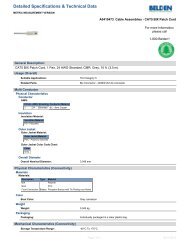
<strong>Coaxial</strong> <strong>Cables</strong> <strong>and</strong> <strong>Applications</strong><br />
Contributed By:<br />
Martin J. Van Der Burgt<br />
Senior Product Engineering Project Manager,<br />
<strong>Belden</strong> Electronics Division<br />
Overview: <strong>Coaxial</strong> cables are perhaps the<br />
most common, basic, <strong>and</strong> easy to underst<strong>and</strong><br />
cables of common transmission line designs.<br />
Basically, they are used to transmit electrical<br />
energy, or signals, from one location to another:<br />
to connect a source to a load, such as a<br />
transmitter to an antenna. This is accomplished<br />
with a transverse electrometic (TEM) wave field<br />
distribution propagation within the transmission<br />
line, or coaxial cable, <strong>and</strong> is governed by<br />
transmission line theory.<br />
<strong>Coaxial</strong> Cable (coax) is typically identified or<br />
classified according to its impedance or RG-type.<br />
For example, a 50-ohm coax or an RG-8 type<br />
coax. This chapter will examine flexible coax<br />
cable in more detail <strong>and</strong> explain the basic<br />
construction, electrical, <strong>and</strong> application<br />
characteristics.<br />
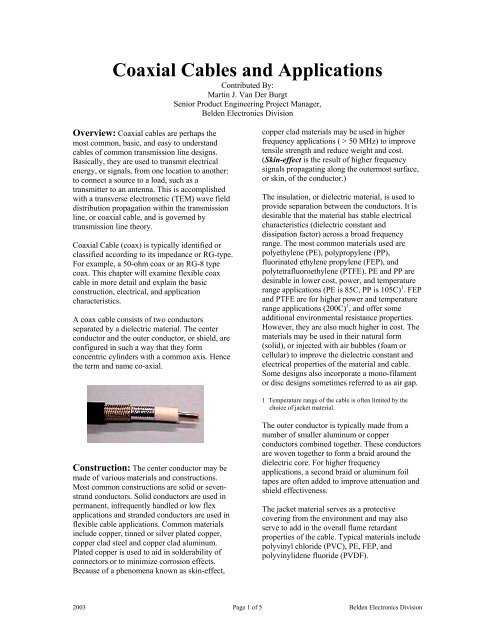
A coax cable consists of two conductors<br />
separated by a dielectric material. The center<br />
conductor <strong>and</strong> the outer conductor, or shield, are<br />
configured in such a way that they form<br />
concentric cylinders with a common axis. Hence<br />
the term <strong>and</strong> name co-axial.<br />
Construction: The center conductor may be<br />
made of various materials <strong>and</strong> constructions.<br />
Most common constructions are solid or sevenstr<strong>and</strong><br />
conductors. Solid conductors are used in<br />
permanent, infrequently h<strong>and</strong>led or low flex<br />
applications <strong>and</strong> str<strong>and</strong>ed conductors are used in<br />
flexible cable applications. Common materials<br />
include copper, tinned or silver plated copper,<br />
copper clad steel <strong>and</strong> copper clad aluminum.<br />
Plated copper is used to aid in solderability of<br />
connectors or to minimize corrosion effects.<br />
Because of a phenomena known as skin-effect,<br />
copper clad materials may be used in higher<br />
frequency applications ( > 50 MHz) to improve<br />
tensile strength <strong>and</strong> reduce weight <strong>and</strong> cost.<br />
(Skin-effect is the result of higher frequency<br />
signals propagating along the outermost surface,<br />
or skin, of the conductor.)<br />
The insulation, or dielectric material, is used to<br />
provide separation between the conductors. It is<br />
desirable that the material has stable electrical<br />
characteristics (dielectric constant <strong>and</strong><br />
dissipation factor) across a broad frequency<br />
range. The most common materials used are<br />
polyethylene (PE), polypropylene (PP),<br />
fluorinated ethylene propylene (FEP), <strong>and</strong><br />
polytetrafluoroethylene (PTFE). PE <strong>and</strong> PP are<br />
desirable in lower cost, power, <strong>and</strong> temperature<br />
range applications (PE is 85C, PP is 105C) 1 . FEP<br />
<strong>and</strong> PTFE are for higher power <strong>and</strong> temperature<br />
range applications (200C) 1 , <strong>and</strong> offer some<br />
additional environmental resistance properties.<br />
However, they are also much higher in cost. The<br />
materials may be used in their natural form<br />
(solid), or injected with air bubbles (foam or<br />
cellular) to improve the dielectric constant <strong>and</strong><br />
electrical properties of the material <strong>and</strong> cable.<br />
Some designs also incorporate a mono-filament<br />
or disc designs sometimes referred to as air gap.<br />
1 Temperature range of the cable is often limited by the<br />
choice of jacket material.<br />
The outer conductor is typically made from a<br />
number of smaller aluminum or copper<br />
conductors combined together. These conductors<br />
are woven together to form a braid around the<br />
dielectric core. For higher frequency<br />
applications, a second braid or aluminum foil<br />
tapes are often added to improve attenuation <strong>and</strong><br />
shield effectiveness.<br />
The jacket material serves as a protective<br />
covering from the environment <strong>and</strong> may also<br />
serve to add in the overall flame retardant<br />
properties of the cable. Typical materials include<br />
polyvinyl chloride (PVC), PE, FEP, <strong>and</strong><br />
polyvinylidene fluoride (PVDF).<br />
2003 Page 1 of 5 <strong>Belden</strong> Electronics Division
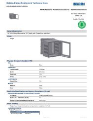
Agency Requirements: As mentioned in<br />
the overview, coax cables are typically identified<br />
or classified according to their impedance or RGtype.<br />
RG, or Radio Guide, is the manner that the<br />
military used to identify transmission lines. The<br />
RG number specified the physical construction,<br />
materials, physical, mechanical <strong>and</strong> electrical<br />
requirements of the cable. This methodology is<br />
now obsolete <strong>and</strong> the military has changed to<br />
“slash sheets” for identification. For example,<br />
RG-58C is now M17/155-00001 or M17/28-<br />
RG058. Today, the RG number has become a<br />
generic identifier, telling the user of it’s general<br />
construction <strong>and</strong> electrical properties, but not<br />
specific enough to compare attributes from one<br />
product to another. Products (<strong>and</strong> manufacturers)<br />
that are recognized as military specification<br />
(MIL-Spec) approved are published in the<br />
Qualified Parts List (QPL). These products are<br />
compliant with a specific slash sheet, <strong>and</strong> are<br />
tested in accordance with the latest revision of<br />
MIL-C-17, currently revision G. Today the<br />
majority of cable applications do not require a<br />
MIL-Spec cable.<br />
The most common agency requirement is for the<br />
cable to comply with the National Electric Code<br />
(NFPA-70) for its specific intended use <strong>and</strong><br />
application. This document requires specific<br />
material physical properties <strong>and</strong> flame/smoke<br />
attributes for safety. The most common agencies<br />
to list <strong>and</strong>/or recognize compliance to the NEC<br />
are Underwriters Laboratories (UL) <strong>and</strong> Intertek<br />
Testing Services (ETL). Cable manufactures will<br />
document in their product literature <strong>and</strong> on the<br />
cable itself the appropriate listings for a specific<br />
cable. It is important that the end user confirm<br />
with the local electrical, fire, <strong>and</strong> building<br />
inspectors to ensure that the appropriate cable is<br />
selected for the intended use <strong>and</strong> application.<br />
The following table lists the common NEC<br />
listings for communication cables (Article 800<br />
Communications Circuits).<br />
Cable Listing Location<br />
CMP Suitable for use in ducts, plenums, <strong>and</strong><br />
(NFPA-262, FT6) other space used for environmental air.<br />
CMR<br />
Suitable for use in<br />
(UL-1666)<br />
vertical runs in a shaft.<br />
CMG<br />
Suitable for general-purpose<br />
(UL-1685,<br />
communication use, with the<br />
IEEE-1202, FT4)<br />
CM<br />
(UL-1685)<br />
exception of risers <strong>and</strong> plenums.<br />
CMX<br />
Suitable for use in dwellings<br />
(UL-1581 VW-1) <strong>and</strong> for use in raceway.<br />
NFPA-70 c2002<br />
In addition, there are other articles in the NEC<br />
for other cable applications, such as Article 725<br />
for Class1, Class 2 <strong>and</strong> Class 3 Remote-Control,<br />
Signaling, <strong>and</strong> Power-Limited Circuits.<br />
Recognized Appliance Wiring Material or AWM<br />
is also common among coaxial cable. These are<br />
less stringent than the NEC requirements <strong>and</strong> are<br />
intended for use with internal wiring.<br />
Electrical Properties: The most common<br />
electrical property referred to in coax cable is the<br />
characteristic impedance, or simply impedance.<br />
Impedance is the total opposition to the flow of<br />
electrical energy within the cable. It is a complex<br />
value defined by the cable’s resistance,<br />
capacitance, inductance, <strong>and</strong> conductance, <strong>and</strong> is<br />
the equivalent value of these items combined. It<br />
is the most important characteristic to discuss<br />
since it is derived from all the other electrical<br />
properties in the cable. It is not length dependent,<br />
<strong>and</strong> is expressed in Ohms. Coax cable is<br />
typically designed as 50 ohm, 75 ohm, <strong>and</strong> 93<br />
ohm depending upon the application. A simple<br />
formula to determine the impedance of a coaxial<br />
cable is:<br />
⎛ D ⎞<br />
Zo = 138 * Vp * log 10⎜<br />
⎟<br />
⎝ d ⎠<br />
Where: Zo = Characteristic Impedance<br />
Vp = Velocity of Propagation<br />
D = Diameter of the Dielectric<br />
d = Diameter of the Conductor<br />
Characteristic Impedance is commonly measured<br />
using a Time Domain Reflectometer (TDR),<br />
such as a Tektronix 11801C digital sampling<br />
oscilloscope with SD-24 TDR/sampling head, on<br />
a 10 ft. length of cable (2).<br />
Capacitance is the ability of the cable to hold a<br />
charge. The larger the capacitance value, the<br />
longer it takes a signal to reach full amplitude<br />
within the cable. Therefore, higher capacitance is<br />
usually a bad attribute. Capacitance is length<br />
dependent <strong>and</strong> is expressed in pF/ft.<br />
7. 36*<br />
ε r<br />
C =<br />
⎛ D ⎞<br />
log 10⎜<br />
⎟<br />
⎝ d ⎠<br />
Where: εr = Dielectric Constant<br />
2003 Page 2 of 5 <strong>Belden</strong> Electronics Division
Capacitance is commonly measured using a<br />
capacitance meter, such as a Hewlett-Packard<br />
4194A Impedance/Gain-Phase Analyzer, at 1<br />
kHz on a 10 ft. length of cable.<br />
Velocity of Propagation is the speed at which a<br />
signal travels through the cable with respect to<br />
the speed of light. This value is typically<br />
represented as a percentage of the speed of light<br />
in free space. For example, solid PE is 66%<br />
while foam PE may be as high as 87%. This may<br />
be an important attribute if running several<br />
signals/cables in parallel, as it is important for all<br />
signals to arrive at (generally) the same time.<br />
This attribute may also be referred to as delay<br />
(nS/ft).<br />
Vp =<br />
1<br />
εr<br />
Delay = 1 . 0167164 × ε<br />
Velocity is commonly measured using the<br />
resonance method on a network analyzer, such as<br />
the Hewlett-Packard 8751A, on a 10 – 15 ft.<br />
length of cable.<br />
Attenuation is the inherent signal power loss<br />
within the cable. It is dependent upon the cable<br />
design <strong>and</strong> is both frequency <strong>and</strong> length<br />
dependent. It is most effected by DC resistance<br />
of the center conductor <strong>and</strong> dissipation factor of<br />
the dielectric material. Attenuation is typically<br />
expressed in db/100ft.<br />
Attenuation is commonly measured using a<br />
network analyzer, such as the Agilent 8753ES on<br />
a 100 ft. length of cable.<br />
Reflection Losses are based upon signals<br />
reflecting back to the source rather than<br />
propagating through the cable. These reflections<br />
are caused by impedance mismatches or<br />
variations typically as a result of minute physical<br />
changes in the cable. R<strong>and</strong>omly spaced<br />
throughout the cable, these mismatches will<br />
cause minimal loss, but when spaced<br />
periodically, that is at the same repeat distance,<br />
they add up together causing a large loss<br />
corresponding to that period wavelength<br />
(frequency). This loss can be minimized by<br />
quality cable manufacturing techniques <strong>and</strong><br />
proper installation practices. This reflective loss<br />
r<br />
is typically expressed as Structural Return Loss<br />
(SRL) or Return Loss (RL) in dB for 75 ohm<br />
cables <strong>and</strong> as Voltage St<strong>and</strong>ing Wave Ratio<br />
(VSWR) for 50 ohm cables. The difference<br />
between these values is that SRL is a<br />
measurement of impedance variation within the<br />
cable with respect to the actual cable<br />
characteristic impedance, while RL <strong>and</strong> VSWR<br />
measure variation from a fixed source<br />
impedance. This can be an important difference<br />
if the application can not compensate for cable<br />
impedance mismatch.<br />
Return Loss is commonly measured using a<br />
network analyzer, such as the Agilent 8753ES<br />
(with option 010), on a 150 ft. length of cable.<br />
Power H<strong>and</strong>ling capability is dependent on the<br />
thermal dissipation <strong>and</strong> maximum voltage<br />
withst<strong>and</strong> properties of the cable design. The<br />
power rating is based upon the permissible rise<br />
in temperature above ambient, <strong>and</strong> is mostly<br />
dependent upon the temperature properties of the<br />
dielectric material. The values typically assume a<br />
low RL or VSWR value <strong>and</strong> 20C ambient<br />
temperature in air. Burying cables, or other<br />
installation variances, will alter this capability.<br />
Manufacturers typically publish this data for<br />
transmission lines, <strong>and</strong> may have it available by<br />
special request for other cables.<br />
Physical Properties: The mechanical <strong>and</strong><br />
physical properties may be critical in selecting<br />
the appropriate cable for the application.<br />
Physical Dimensions are critical to assure that<br />
an industry st<strong>and</strong>ard connector is available.<br />
Other odd-size dimensions will require use of a<br />
custom termination. Diameter of the center<br />
conductor, core, <strong>and</strong> jacket are the critical<br />
values.<br />
Temperature Rating, which may be listed as<br />
operational or storage, provides the limitations<br />
on temperature extremes that the cable material<br />
can h<strong>and</strong>le. This safe range, based upon the<br />
thermal properties of the dielectric <strong>and</strong> jacket<br />
materials, assures that the product will not<br />
fracture, melt, or otherwise deform resulting in<br />
electrical or mechanical failures.<br />
Bend Radius <strong>and</strong> Flex Radius are the minimum<br />
values for these attributes. Adherence to these<br />
guidelines will minimize the degradation of the<br />
cable due to cold flow <strong>and</strong> other stress/material<br />
properties in the application. Bend radius is for<br />
2003 Page 3 of 5 <strong>Belden</strong> Electronics Division
permanent install <strong>and</strong> flex radius is for flexing.<br />
Flex radius should not be misunderstood to mean<br />
that the cable is designed for continuous flexing.<br />
Pulling Tension is the maximum load bearing<br />
weight for the cable. It is typically a safe value<br />
well below the break strength of the cable.<br />
Staying below this maximum assures that the<br />
conductor will not be stretched resulting in<br />
electrical performance problems in the cable.<br />
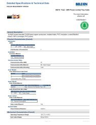
<strong>Applications</strong>: One of the broadest uses of<br />
coaxial cable is for video distribution. From<br />
CATV signals around the neighborhood to<br />
precision digital signals in a post-production<br />
studio, these signals are routed on 75 ohm<br />
coaxial cable. Broadb<strong>and</strong> CATV (or MATV)<br />
signals typically use a series 59 (RG-59) or<br />
series 6 (RG-6) type coaxial cable, or drop cable.<br />
These cables use copper covered steel<br />
conductors <strong>and</strong> aluminum foil/braid combination<br />
shields (outer conductors). They are designed for<br />
use above 50 MHz, with high strength, low<br />
weight <strong>and</strong> low cost the primary factors. These<br />
cables are all typically designed to a SCTE<br />
st<strong>and</strong>ard <strong>and</strong> are a commodity-type item.<br />
Electrical performance is good <strong>and</strong> clearly<br />
defined in the industry st<strong>and</strong>ards. <strong>Cables</strong> used in<br />
outdoor environments typically utilize a<br />
polyethylene jacket material. The distribution<br />
trunk cable is series 11 (RG-11) type or larger –<br />
typically “hard line” cable utilizing a corrugated<br />
copper outer conductor. These cables are<br />
designed for minimum attenuation <strong>and</strong> good<br />
power h<strong>and</strong>ling capability.<br />
Another type of 75 ohm video cable is st<strong>and</strong>ard<br />
video cable. These cables are based upon<br />
st<strong>and</strong>ard RG-type designs, utilizing copper<br />
covered steel, copper, or tinned copper<br />
conductors <strong>and</strong> bare or tinned copper braid only<br />
shields. This cable is used primarily for CCTV,<br />
security, surveillance, <strong>and</strong> other “non-critical”<br />
video applications – video for consumption that<br />
will not be manipulated, saved, or used for other<br />
purposes. These cables are not typically<br />
associated with an industry st<strong>and</strong>ard, so there is<br />
much variation <strong>and</strong> differentiation among<br />
available designs. Typical cables specify<br />
nominal electrical values only.<br />
The high end of video cables is precision video<br />
cable. These cables are loosely based upon the<br />
st<strong>and</strong>ard RG-type designs. They have solid bare<br />
copper conductors, foam dielectric, combination<br />
foil <strong>and</strong> 95% tinned copper braid shields. They<br />
are designed for maximum b<strong>and</strong>width, minimum<br />
return loss, <strong>and</strong> minimum attenuation loss. The<br />
cables have very tight requirements on all<br />
electrical attributes <strong>and</strong> are used for both analog<br />
<strong>and</strong> digital video in broadcast, post-production,<br />
<strong>and</strong> other critical video applications.<br />
There are also many specialty types of video<br />
cables, such as S-VHS, RGB, DBS, <strong>and</strong> Triax to<br />
name a few.<br />
<strong>Cables</strong> used for two-way communication, RF<br />
<strong>and</strong> microwave transmission, data transmission<br />
<strong>and</strong> instrumentation/control are typically 50 ohm<br />
coaxial cables. These cables are based upon<br />
MIL-Spec designs <strong>and</strong> are most often referred to<br />
by their RG type number. The cables fall into a<br />
few categories: Transmission <strong>and</strong> computer<br />
cables that are based upon RG type designs, but<br />
not per the current MIL-Spec; MIL-C-17 QPL<br />
cables that are in compliance with the current<br />
MIL-Spec; <strong>and</strong> low-loss cables based loosely<br />
upon RG type designs. The RG type cables are<br />
the most used products since the majority of<br />
cable applications do not require QPL cables.<br />
Furthermore, most manufacturers have a limited<br />
availability of QPL cables for this reason. The<br />
major differences between the cables are<br />
typically the type of PVC jacket material used<br />
<strong>and</strong> less stringent electrical <strong>and</strong> physical<br />
requirements. For wireless <strong>and</strong> antenna<br />
applications, the low-loss cables are gaining<br />
popularity because of their size, weight, cost, <strong>and</strong><br />
performance advantages over the traditional<br />
designs. These cables typically utilize a foamed<br />
dielectric material <strong>and</strong> combination foil/braid<br />
shields.<br />
Other impedance cables are used for data<br />
transmission <strong>and</strong> instrumentation/control. These<br />
are typically 93 ohm or 125 ohm <strong>and</strong> are not as<br />
common as they once were. As with the<br />
transmission <strong>and</strong> computer cables, the majority<br />
of cables used are RG type cables with minimal<br />
use of QPL product.<br />
Specialty coaxial cables include low-noise <strong>and</strong><br />
musical interconnects cables. These are<br />
specially designed to minimize piezoelectric <strong>and</strong><br />
triboelectric noise in cables <strong>and</strong> are not for RF<br />
use. The cables may be loosely based upon RG<br />
type designs, but utilize semi-conductive<br />
material layers within the cable.<br />
2003 Page 4 of 5 <strong>Belden</strong> Electronics Division
Conclusion:<br />
Hopefully this chapter has given you a brief<br />
overview of coaxial cable <strong>and</strong> a better insight to<br />
the relevant design properties. When choosing a<br />
cable for your application, work backwards from<br />
the end-need requirements. What is the specific<br />
application? Do you know what impedance is<br />
required? What is the frequency of interest?<br />
What is the loss budget (how much cable<br />
attenuation loss is allowed)? How long is the<br />
cable run length? Indoor or outdoor? Are there<br />
agency requirements (UL, NEC, AWM, MIL-<br />
Spec, etc.)? What connector type will be used?<br />
These few questions should help you easily<br />
identify an appropriate coaxial cable.<br />
Martin J. Van Der Burgt<br />
Marty is a Senior Product Engineering Project<br />
Manager for <strong>Belden</strong> Electronics Division. His<br />
experience encompasses project management<br />
<strong>and</strong> product development positions. He<br />
currently has responsibility for all design <strong>and</strong><br />
development efforts, <strong>and</strong> manages the day-to-day<br />
activity of product engineers, for <strong>Belden</strong>’s<br />
entertainment, service provider, <strong>and</strong> industrial<br />
product market areas, <strong>and</strong> has recently filed an<br />
application for his first patent. Marty received<br />
his Bachelor of Science Degree in Electrical<br />
Engineering (BSEE) from Marquette University,<br />
Milwaukee, WI in 1992 <strong>and</strong> has been with<br />
<strong>Belden</strong> since that time. He is a member of<br />
several professional organizations <strong>and</strong> st<strong>and</strong>ards<br />
bodies, <strong>and</strong> has had several articles on<br />
Audio/Video <strong>and</strong> RF topics published in trade<br />
magazines <strong>and</strong> journals. Most recently, coauthored<br />
tutorials on “High-Definition Cabling<br />
<strong>and</strong> Return Loss” in the January 2001 SMPTE<br />
Journal <strong>and</strong> “Impedance” in the 2002 NAB<br />
Broadcast Engineering Conference Proceedings.<br />
Marty also holds a FCC Amateur Extra Class<br />
amateur radio license. He <strong>and</strong> his wife Beth live<br />
in Richmond, IN.<br />
Marty Van Der Burgt<br />
2003 Page 5 of 5 <strong>Belden</strong> Electronics Division