

![Download Pdf [2,77 MB] - MTU Aero Engines](https://img.yumpu.com/11154943/1/500x640/download-pdf-277-mb-mtu-aero-engines.jpg)
Download Pdf [2,77 MB] - MTU Aero Engines
Download Pdf [2,77 MB] - MTU Aero Engines
Download Pdf [2,77 MB] - MTU Aero Engines

You also want an ePaper? Increase the reach of your titles
YUMPU automatically turns print PDFs into web optimized ePapers that Google loves.
<strong>MTU</strong> <strong>Aero</strong> <strong>Engines</strong> Holding AG<br />
Dachauer Straße 665<br />
80995 Munich • Germany<br />
Tel. +49 89 1489-0<br />
Fax +49 89 1489-5500<br />
info@mtu.de<br />
www.mtu.de<br />
Pioneering new core<br />
engine technologies<br />
Customers + Partners Technology + Science<br />
Products + Services<br />
A cargo workhorse in<br />
the skies<br />
K3 –<br />
cool coating<br />
Adaptive<br />
laser welding<br />
2/2010
Contents<br />
Cover Story<br />
Pioneering new core engine<br />
technologies<br />
Interview with Airbus: The right<br />
technologies at the right time<br />
Customers + Partners<br />
The Chancellor’s new jetliner<br />
A cargo workhorse in the skies<br />
Technology + Science<br />
Power from algae<br />
K3—cool coating<br />
Products + Services<br />
Adaptive laser welding<br />
The final touches<br />
MAX1—a great leap forward<br />
Report<br />
Make it clean and keep it clean<br />
In Brief<br />
Masthead<br />
4 – 9<br />
10 – 11<br />
12 – 15<br />
16 – 19<br />
20 – 25<br />
26 – 29<br />
30 – 33<br />
34 – 37<br />
38 – 39<br />
40 – 43<br />
44 – 47<br />
47<br />
Pioneering new core engine technologies<br />
Under the <strong>MTU</strong>-led NEWAC technology program 40 partners from industry and<br />
research have worked together for four years to improve the core engine. The<br />
impressive result: a reduction in CO 2 emissions by six percent and in NO X emissions<br />
by 16 percent. Page 4<br />
A cargo workhorse in the skies<br />
The C-17 Globemaster III transport aircraft<br />
has been a major player in every recent humanitarian<br />
relief mission. It is powered by<br />
F117 engines, which have been produced by<br />
Pratt & Whitney in partnership with <strong>MTU</strong><br />
since 1993.<br />
Page 16<br />
Adaptive laser welding<br />
K3—cool coating<br />
To protect engine blades and<br />
vanes or casing components<br />
from corrosion and wear or repair<br />
damage <strong>MTU</strong> is using the<br />
newly developed kinetic cold gas<br />
spraying process, which opens<br />
up entirely new possibilities.<br />
Page 26<br />
A fully automated and highly efficient system: <strong>MTU</strong> has developed a new machine<br />
concept for the precise dimensional inspection of parts and subsequent repair of<br />
damaged areas by laser powder cladding.<br />
Page 30<br />
Editorial<br />
2 3<br />
Dear Readers:<br />
<strong>MTU</strong> <strong>Aero</strong> <strong>Engines</strong>’ products and services are<br />
among the finest to be found in the global<br />
marketplace. The company excels in particular<br />
in the areas of low-pressure turbines and<br />
high-pressure compressors, as well as repair<br />
and manufacturing processes. These core<br />
competencies make us a must-have partner<br />
in the engine industry. Our success is the<br />
result of decades of intensive research work<br />
performed both in-house and in cooperation<br />
with partners from industry and academe. To<br />
remain at the top of the game, we are continuing<br />
to invest in R&D. In 2010, we will<br />
spend 230 million euros, which is around ten<br />
million more than in the year before. For it is<br />
only through innovation that we will be able<br />
to maintain our position as a technology leader.<br />
With this approach we intend to secure the<br />
company’s competitiveness long-term and to<br />
help make air travel cleaner in the future.<br />
Under its three-stage Claire technology program,<br />
<strong>MTU</strong> has succeeded in making a major<br />
contribution towards the development of the<br />
propulsion concept of the future. It bases on<br />
the geared turbofan (GTF), which we are building<br />
in partnership with Pratt & Whitney and<br />
which features a high-speed low-pressure<br />
turbine. Our key areas of research are lowpressure<br />
turbines and high-pressure compressors.<br />
But apart from these, we are also<br />
dedicating significant technological efforts to<br />
the further development of the overall engine<br />
system, for example, by highly advanced thermodynamic<br />
cycles with markedly improved<br />
thermal efficiencies. In the process, we closely<br />
cooperate with other companies, with universities<br />
and research institutes at a regional,<br />
national and European level.<br />
One of the most important projects pursued<br />
is the <strong>MTU</strong>-led European NEWAC (New <strong>Aero</strong><br />
Engine Core Concepts) technology program.<br />
The results of the four years of intensive research<br />
work performed under the program<br />
were announced just recently. The efforts to<br />
develop new core engine concepts have<br />
yielded an impressive combination of technical<br />
innovations and environmentally sound<br />
technologies, and the outcome is also tangible<br />
proof of how successful joint research can<br />
be. Such programs, sponsored by the European<br />
Commission, are vital to all industry<br />
players in Europe, because they provide a<br />
platform for blazing new trails in engine technology.<br />
The above examples go to show that <strong>MTU</strong> is<br />
continuously investing in novel products and<br />
engine services. Thus, we make sure that the<br />
company remains a driver of innovation and<br />
a valued and reliable partner in the engine<br />
industry.<br />
Sincerely yours,<br />
Ihr<br />
Dr. Rainer Martens<br />
Member of the Board of Management,<br />
Chief Operating Officer
Pioneering new core<br />
engine technologies<br />
4 Cover Story<br />
By Denis Dilba<br />
Four years of research conducted as part of the New <strong>Aero</strong> Engine Core Concepts technology program—NEWAC<br />
for short—have produced results that once again illustrate just how much can be achieved when industry and<br />
research partners work together on a European level. With active systems, heat management and advanced<br />
combustors, the newly developed core engine concepts feature an impressive mix of technical innovations and<br />
environmentally sound technologies.<br />
Active compressor on <strong>MTU</strong>’s rig 260.<br />
The Advisory Council for <strong>Aero</strong>nautics Research<br />
in Europe (ACARE) wants the aviation<br />
industry to explore radically new technologies<br />
as it works to meet environmental standards<br />
for the next generations of aircraft. A<br />
glance at the figures shows that the industry<br />
will need to halve fuel consumption, CO2<br />
emissions and noise levels by 2020 relative<br />
to year-2000 aircraft, while also slashing<br />
emissions of oxides of nitrogen by 80 percent.<br />
Regarding noise and NO X emissions<br />
future engines will need to contribute the<br />
lion’s share and in terms of fuel consumption<br />
some 20 percent of these improvements. All<br />
this obviously comes as no surprise to the<br />
engine manufacturers, who have spent years<br />
ploughing resources into research programs<br />
such as EEFAE, VITAL and DREAM with the<br />
goal of finding technological solutions to<br />
achieve the drastic cuts in consumption and<br />
emissions that are required over today’s engines.<br />
The recent presentation on the five-year<br />
NEWAC project, which is co-funded by the<br />
European Commission under the Sixth Framework<br />
Programme for Research and Technology<br />
Development, provided the perfect<br />
opportunity to judge how far manufacturers<br />
have already come. Under the leadership of<br />
<strong>MTU</strong> <strong>Aero</strong> <strong>Engines</strong>, 40 partners were working<br />
towards cutting CO2 emissions by six percent<br />
and NOX emissions by 16 percent by<br />
making improvements to the core engine.<br />
The NEWAC project is split into five key areas<br />
of research—four core engine concepts plus<br />
a sub-project to investigate lean combustion<br />
processes—and testing has already been successfully<br />
completed in some areas.<br />
The greatest potential for cutting fuel consumption<br />
and thus reducing CO2 emissions<br />
lies in the combined use of heat exchangers<br />
(recuperators) and intercoolers in the engine.<br />
“The idea here is that the recuperator elements<br />
use the residual heat from the exhaust<br />
gas stream to pre-heat the air entering<br />
the combustor,” says Stefan Donnerhack,<br />
technical expert at <strong>MTU</strong> <strong>Aero</strong> <strong>Engines</strong> in<br />
Munich and head of the Intercooled Recuperative<br />
<strong>Aero</strong>-Engine (IRA) research team.<br />
The approach makes it possible to achieve<br />
the same turbine entry temperature as in a<br />
conventional engine, but with less fuel.<br />
5
Blade profile aspiration being tested at EPFL (École<br />
Polytechnique Fédérale de Lausanne).<br />
Donnerhack says their previous work under<br />
the Clean project had already confirmed they<br />
were on the right track with their chosen concept<br />
of a profiled-tube recuperator: “Our work<br />
on the IRA focuses on the optimum arrangement<br />
of the recuperator modules in the ex-<br />
Intercooled engine intercase prototypes.<br />
6 Cover Story<br />
Abrasive coatings were tested on a Sulzer test facility. Snecma compressor rig.<br />
haust gas stream and the development of a<br />
new radial compressor.” There were two good<br />
reasons for a new radial compressor, adds<br />
the <strong>MTU</strong> expert: It is well suited for an engine<br />
with a comparatively low overall pressure<br />
ratio of between 20:1 and 25:1 in the IRA<br />
cycle, and it also discharges the air radially<br />
outward, as its name suggests, which is precisely<br />
where it needs to go anyway in order<br />
to be routed past the combustor and reach<br />
the recuperator.<br />
NEWAC partner Turbomeca, a French manufacturer<br />
of engines for aircraft and helicopters<br />
and a specialist in the field of radial<br />
compressors, has managed to reduce the<br />
weight of the new compressor more than ten<br />
percent while boosting efficiency by approximately<br />
one percent. Donnerhack is confident<br />
that improvements to the airflow through the<br />
recuperator will help reduce IRA fuel consumption<br />
by a further two percentage points<br />
in addition to the 16 percent already achieved<br />
under Clean. He also notes that the<br />
overall IRA engine system will be around one<br />
percent lighter. Final rig tests are scheduled<br />
to take place over the next few months.<br />
Rolls-Royce researcher Nick Baker, who<br />
heads up the Intercooled Core (IC) project of<br />
NEWAC, has developed an intercooler that<br />
could also be used in a modified form in the<br />
IRA. “The main advantage of the Intercooled<br />
Core concept is that it is not quite as complex<br />
as the IRA,” says Baker. Nonetheless,<br />
the task of developing the IC is far from simple.<br />
The intercooler needs to be ultra-compact<br />
and as lightweight as possible, which is<br />
what prompted Baker and his NEWAC partners<br />
to use a rapid prototyping technique to<br />
produce an intercooler in titanium. Its corrugated<br />
sheet structure has already demonstrated<br />
impressive performance in initial trials,<br />
according to Baker. The job to be done<br />
now is to make it even smaller.<br />
Baker’s project team has also been working<br />
on the design of the flow ducts that feed air<br />
to the intercooler modules and then back to<br />
the high-pressure compressor. Minimizing the<br />
pressure losses in this area has been challenging,<br />
Baker explains. Integrating the intercooler<br />
has also required the team to optimize<br />
the compressors and make the engine casing<br />
more rigid. Although efforts are still ongoing<br />
to meet the goal of four percent reduced fuel<br />
consumption relative to a conventional engine,<br />
Baker says: “NEWAC is already the most<br />
successful EU project I have ever worked on.”<br />
The Rolls-Royce expert is confident that the<br />
targets will be met within a year or so. “And<br />
we will keep working on these new technologies<br />
even after NEWAC comes to an end,” he<br />
adds. The first technologies developed under<br />
NEWAC are likely to appear in production<br />
engines from 2020 at the earliest. “But for<br />
engine manufacturers like us that feels like<br />
no time at all,” states Wolfgang Sturm, who<br />
works at <strong>MTU</strong> and heads up research into<br />
the Active Core concept, emphasizing the<br />
Setup for testing of the active clearance control system.<br />
Advanced compressor rotor.<br />
importance of this research work. Sturm explains<br />
that one of the key elements of his<br />
active core engine is a smart compressor<br />
that adapts itself to varying operating conditions.<br />
To pull off this impressive feat of engineering,<br />
his team developed an active clearance<br />
control system. The sensors in this system<br />
continuously monitor the clearance and<br />
use actuators to adjust the casing so that the<br />
compressor is constantly working at optimum<br />
efficiency.<br />
The team also developed what is known as a<br />
tip injection system. “That’s where we addi-<br />
7
8 Cover Story<br />
If the cooling air is colder than in today’s engines,<br />
significantly less air is needed for the<br />
remaining cooling tasks in the engine, such<br />
as turbine blade cooling. “And that boosts<br />
the engine’s efficiency,” says Sturm. But<br />
everything is a question of balance. If the difference<br />
in temperature between the cooling<br />
air and the hot gas in the turbine becomes<br />
too great, the turbine’s service life will drop<br />
markedly. Sturm and his NEWAC colleagues<br />
therefore had to design a system to actively<br />
control the temperature of the cooling air.<br />
The result was a 1.5 percent drop in fuel consumption<br />
and 0.5 percent increase in the<br />
efficiency of the high-pressure turbine with<br />
enhanced cooling. The active core engine<br />
now requires some 20 percent less cooling<br />
air overall than before, says Sturm, and the<br />
technologies used in the smart high-pressure<br />
compressor have improved its efficiency by<br />
two percent. “We have only just finished our<br />
rig tests and we still have to analyze and assess<br />
all the data,” the <strong>MTU</strong> expert adds, “but<br />
it is already clear that these technologies<br />
offer great potential for the future.” Sturm<br />
and his team are obviously keen to continue<br />
pursuing development work in this area, ide-<br />
ally in a follow-up project of a similar kind so<br />
that they can continue to reap the benefits of<br />
the excellent collaboration with their partners—one<br />
of the key factors that has made<br />
their work so successful.<br />
Hanna Reiss of French engine manufacturer<br />
Snecma, who heads up research into the<br />
Flow Controlled Core (FCC) concept, too, has<br />
nothing but praise for the positive working<br />
atmosphere in NEWAC. Her project team has<br />
developed and tested four different approaches<br />
to improve the efficiency of the highpressure<br />
compressor. According to Reiss, the<br />
new engines can achieve their full potential<br />
only if the compressor design is optimized<br />
for high pressure ratios. The FCC approach<br />
involves local control of the airflow in the<br />
high-pressure compressor. This required multistage<br />
3D CFD (Computational Fluid Dynamics)<br />
optimization combined with advanced<br />
flow control technologies.<br />
Two <strong>MTU</strong> employees are fitting the instrumentation for the experimental compressor. Full-annular combustor rig setup for low-pressure test at Avio.<br />
tionally blow air from the outside into the forward<br />
compressor stages,” says Sturm, explaining<br />
that this helps improve stability at<br />
part load conditions. The third key aspect of<br />
the active core engine is cooling air cooling.<br />
<strong>MTU</strong>’s compressor test facility is extremely powerful.<br />
The team focused in particular on the extraction<br />
of air from the high-pressure compressor<br />
and on reducing performance losses caused<br />
by flow separation. Reiss explains that aspiration<br />
is being investigated both on casing<br />
walls and directly on the blade profiles<br />
through tiny ducts in the blades. The first<br />
method has already been successfully tested<br />
in NEWAC in a new, fully-assembled highpressure<br />
compressor, while preliminary testing<br />
of the second method has shown the<br />
concept to be very promising, according to<br />
Reiss. Testing has also been carried out on<br />
optimized, more durable abradable linings in<br />
the high-pressure compressor casing.<br />
Overall, Reiss and her team have managed to<br />
boost the efficiency of the high-pressure<br />
compressor by 1.9 percent and increase the<br />
surge margin by 7.5 percent. “We are delighted<br />
with the results, but we still need to<br />
find a way of making the systems simpler<br />
and lighter,” says the Snecma manager—<br />
hence the decision to keep working on this<br />
project even after NEWAC comes to an end.<br />
Much of the responsibility for NEWAC meeting<br />
the stipulated target of a 16 percent reduction<br />
in oxides of nitrogen emissions lies<br />
with Salvatore Colantuoni of Italian engine<br />
manufacturer Avio, who heads up research<br />
work in the field of combustors. The new<br />
combustor technologies developed under his<br />
leadership focus on lean combustion. In contrast<br />
to conventional combustion, the new<br />
technologies feature an excess of air in the<br />
combustor rather than fuel. “That is how we<br />
reduce the flame temperature and prevent<br />
the increased formation of oxides of nitrogen,”<br />
Colantuoni explains.<br />
View of the combustor flame at ignition.<br />
However, the extent to which lean combustion<br />
technology can be applied to different<br />
engine sizes and overall pressure ratios is<br />
very limited, which is why Colantuoni’s team<br />
decided to work on three different concepts<br />
in parallel: Lean Direct Injection (LDI), Lean<br />
Premixed Prevaporized (LPP) and Partially<br />
Evaporated and Rapid Mixing (PERM). “LPP is<br />
well suited for the comparatively low overall<br />
pressure ratios of intercooled recuperated<br />
engines,” says the combustion expert. PERM<br />
is suitable for average pressure ratios, while<br />
LDI development is primarily aimed at the<br />
intercooled core engine, which has the highest<br />
pressures. All three lean combustion<br />
concepts were tested on demonstrators and<br />
produced very good results in terms of<br />
reducing NO X emissions, according to Colantuoni.<br />
The next steps are to optimize the weight<br />
and reduce the complexity of the system, a<br />
process that will require the team to take an<br />
even closer look at the interaction between<br />
the new combustors and the components<br />
closest to them—the high-pressure compressor<br />
and the high-pressure turbine, says<br />
Colantuoni, adding: “The NEWAC developments<br />
have brought us a lot closer to reaching<br />
the ambitious ACARE goals.”<br />
“One of the best things to come out of<br />
NEWAC is the wide selection of innovative<br />
technologies that we have developed, something<br />
that enables us to make immediate<br />
improvements as well as to take some important<br />
long-term steps towards eco-efficient<br />
flight,” says Jörg Sieber, Chief Engineer of the<br />
NEWAC technology program.<br />
“We have achieved our goals,” enthuses<br />
Stephan Servaty, Senior Manager, Technology<br />
Programs at <strong>MTU</strong> and NEWAC coordinator.<br />
The money spent by the EU and the program<br />
partners is an investment that pays dividends:<br />
“It makes a major contribution towards<br />
a cleaner environment, and at the<br />
same time helps Europe’s engine industry to<br />
remain competitive in the global marketplace.”<br />
For additional information, contact<br />
Stephan Servaty<br />
+49 89 1489-4261<br />
For interesting multimedia services<br />
associated with this article, go to<br />
www.mtu.de/210NEWAC<br />
9
The right technologies<br />
at the right time<br />
Sébastien Rémy, VP, Head of CoC Powerplant Airbus S.A.S.<br />
10 Cover Story<br />
Intensive research is undertaken in the engine industry to make tomorrow’s aircraft fuelthriftier,<br />
cleaner and quieter. The aircraft manufacturers, too, are working ceaselessly to<br />
develop new technologies. To learn more about the joint efforts we asked Sébastien Rémy,<br />
Vice President, Head of CoC Powerplant Airbus S.A.S. a few questions.<br />
Mr. Rémy, the European Commission has for<br />
many years sponsored programs to develop<br />
new technologies for engines of the future, a<br />
current example being NEWAC. To what extent<br />
are airframers involved in such programs?<br />
Airbus and engine manufacturers have a long<br />
experience of collaborative work within E.U.<br />
funded frame which has been boosted in the<br />
late 90’/early 2000’ within the EEFAE &<br />
Silencer projects, continued with NEWAC and<br />
now developed with the Clean Sky Programs<br />
(SAGE, SFWA). The Airbus contribution to E.U.<br />
engine led programs always focused on the<br />
evaluation of engine technologies potential<br />
at aircraft level through the definition of generic<br />
aircraft platforms suited to the various<br />
engine options investigated. Final objective<br />
for both engine manufacturers and Airbus is<br />
to get capability to down-select, in a balanced<br />
aircraft level way, the most promising<br />
engine technologies for further developments.<br />
All aircraft manufacturers are presently mulling<br />
over launching a next-generation passenger<br />
aircraft to enter service in 10 to 12 years<br />
at the earliest. In what order of magnitude are<br />
the expected improvements over today’s aircraft<br />
in terms of consumption, emissions and<br />
life-cycle costs?<br />
Airbus is always assessing all options from<br />
continuous improvement of the current product,<br />
with technologies insertion at airframe &<br />
engine level, up to the development of new<br />
airframe combined with new propulsion system.<br />
What drives at the end the selection of<br />
the preferred option is the critical mass of<br />
technological improvement with the related<br />
economical benefits for both OEM and oper-<br />
ators. Expected improvements over the next<br />
couple of decades can easily range from 10 to<br />
35 percent in term of fuel consumption depending<br />
of actual product entry into service<br />
horizon.<br />
Which technical measures will be taken to<br />
make sure these targets are met?<br />
A systematic approach (Technology Readiness<br />
Level) is in place at Airbus to develop<br />
and down-select the most promising technology<br />
options with the ambition to consolidate<br />
the performance potential while reducing the<br />
development risk. This step by step approach<br />
in maturing technologies is well illustrated by<br />
anumber of collaborative E.U. funded projects<br />
covering the full spectrum from academic<br />
work, through scale model tests (typically<br />
Wind Tunnel Tests) up to full scale demonstration<br />
(engine ground test or engine Flying<br />
Test Bed). This systematic down-selection<br />
approach is largely shared between Airbus<br />
and engine manufacturers and has allowed<br />
the introduction of the right technologies at<br />
the right time over the past decades; best<br />
technologies are the ones which find their<br />
route to the market.<br />
Does the industry think about using entirely<br />
new materials that are presently in the development<br />
stage or not even that?<br />
Airbus keeps on developing materials, such<br />
as CFRP, and investigating new materials<br />
which will contribute to aircraft weight reduction,<br />
hence reduced aircraft emissions.<br />
Our vision (and therefore criteria for success)<br />
is however broader, encompassing simplicity<br />
in operation, respecting landscape and biodiversity,<br />
and ecoefficiency (including green<br />
manufacturing and recycling). Some of our<br />
objectives for 2020 are, relative to 2006, to<br />
reduce energy consumption by 30 percent,<br />
CO 2 emissions by 50 percent, water consumption<br />
by 50 percent, water discharge by 80<br />
percent, and waste production by 50 percent.<br />
For instance, significant investment has been<br />
made to eliminate chromates in the painting<br />
process. And water used for surface treatment<br />
can be limited by recycling it, by reducing<br />
evaporation thanks to lower bath temperatures<br />
and by minimising rinse levels as far<br />
as possible. In addition, current practices do<br />
not allow recovering more than, at best, 60<br />
percent (in weight) of aircraft materials. This<br />
situation is no longer acceptable. Not only it<br />
is potentially environmentally damaging<br />
through the release of hazardous materials<br />
Airbus Concept Plane.<br />
and soil pollution, but it also presents safety<br />
risks through the uncontrolled reuse of second<br />
hand spare parts. Last but not least, it is<br />
uneconomical as only a small part of the materials<br />
is recycled. The PAMELA LIFE project,<br />
which supplied its final reports in January<br />
2008, demonstrated that up to 85 percent of<br />
an aircraft’s components can be easily recycled,<br />
reused or recovered, with 70 percent<br />
reuse and recovery. The experience gained in<br />
dismantling and recycling can then be fed<br />
back into the Airbus life cycle (reverse engineering,<br />
manufacturing, supply chain, raw<br />
material etc.), helping to make future aircraft<br />
even easier to recycle.<br />
Which role do the engines play in the achievement<br />
of the ambitious targets?<br />
Future engine technologies are among the<br />
most promising lever arms to improve aviation<br />
efficiency and environmental friendliness.<br />
However, those technologies will only<br />
deliver their full promise in case of a smart<br />
integration to the airframe. This deserves the<br />
cooperation of both actors from the very<br />
early stage of R&T, paving the way to the<br />
optimum airframe/engine technology package<br />
and application. This combined engine/<br />
airframe technologies effort is expected to<br />
deliver as much as 40 percent of fuel consumption<br />
which together with the 10 to 15<br />
percent further reduction expected from<br />
ATM improvements will lead to the 50 percent<br />
fuel reduction ACARE target vs to current<br />
product in operation.<br />
Today’s engines power the aircraft while at<br />
the same time ensuring the energy supply to<br />
the aircraft. Do you think this will also hold<br />
true for future engines or will there be separate<br />
systems?<br />
<strong>Engines</strong> are to date and will remain within the<br />
next decade the most efficient and reliable<br />
energy source on board the aircraft. The objective<br />
of the airframer is to optimize the level<br />
of power-off take which is required from the<br />
engine for non thrust related needs. Some<br />
evolution can be foreseen first in the ground<br />
phase where alternative systems will complement<br />
or take-over from engine, to supply<br />
energy to the aircraft for various functions<br />
(air conditioning…) including taxi phase that<br />
could be assisted with independent electrical<br />
engine fitted on landing gear.<br />
What do you think about the use of the much<br />
discussed fuel cell on aircraft?<br />
Fuel cells can produce electricity in a more<br />
efficient way than combustion engines. They<br />
also offer the perspective to further reduce<br />
aviation emissions footprint. Airbus, DLR and<br />
Michelin have been first, in February 2008,<br />
to fly a commercial airplane with a fuel cell<br />
powering the electric motor pump for the aircraft’s<br />
back-up hydraulic circuit, controlling<br />
the spoilers, ailerons and elevator actuator.<br />
Research activities related to fuel cells are<br />
however at an early stage. Dramatic progress<br />
in fuel cell system power density (ratio of<br />
power produced per unit weight) is still needed<br />
to allow fuel cells to progressively find<br />
their way into commercial aircraft.<br />
For additional information, contact<br />
Odilo Mühling<br />
+49 89 1489-2698<br />
For further information on<br />
this article, go to<br />
www.mtu.de/210Airbus<br />
11
The Chancellor’s<br />
new jetliner<br />
By Patrick Hoeveler<br />
You have probably seen them often on TV, albeit only in the background: The aircraft operated<br />
by the Special Air Mission Wing of the German Federal Ministry of Defense frequently<br />
form part of the decor when the German Chancellor, the German President or other highranking<br />
government officials go on official travel. Two new A319s, procured as part of the<br />
first stage of an extensive fleet modernization program, will significantly improve the air force<br />
unit’s mission capabilities. They are each powered by two IAE International <strong>Aero</strong> <strong>Engines</strong><br />
V2500 engines, in which <strong>MTU</strong> has a stake.<br />
The famous “red phone” featured in numerous<br />
fictional movies does actually exist on<br />
board the two brand-new Airbus A319s—<br />
only it is black, not red. But otherwise the<br />
interior of the jets, with their discrete ivory<br />
and beige paneling and furnishings, is anything<br />
but spectacular, and fully in keeping<br />
with the missions for which they were<br />
designed: transporting VIP passengers on<br />
official government business. This is one of<br />
the main duties of the Special Air Mission<br />
Wing, an air force unit stationed at Wahn airbase<br />
near Cologne, which is also responsible<br />
for military transportation and logistics<br />
support when German troops are posted<br />
abroad.<br />
The A319 is the first in a new generation of<br />
German-government VIP aircraft that will be<br />
gradually introduced as part of a modernization<br />
program to replace the present aging<br />
fleet of Airbus A310s and Canadair CL-601<br />
Challengers, which have been in service for<br />
over 20 years. The first of the two A319<br />
Airbus Corporate Jetliners (ACJ), intended<br />
for medium-haul flights, was fitted out by<br />
Lufthansa Technik and handed over to the<br />
Ministry of Defense at the end of March. The<br />
A319 ACJ’s special VIP cabin was the result<br />
of nine months’ work at the company’s<br />
Hamburg site. The new aircraft will be joined<br />
towards the end of this year by two Airbus<br />
A340-300s for long-haul flights. The Special<br />
Air Mission Wing’s remaining Challengers<br />
will be replaced in 2011 by four Bombardier<br />
Global 5000 jets.<br />
The first of the three new aircraft types to<br />
join the fleet has delighted crew and passengers<br />
alike. “The A319 has significantly<br />
improved the Special Air Mission Wing’s capabilities,”<br />
says Lieutenant Colonel Sascha<br />
Kählert, Captain of the 2nd Squadron. “Most<br />
importantly, it enables us to transport up to<br />
44 people—delegations and crew—, whereas<br />
with the Challenger we were limited to 16.”<br />
With auxiliary tanks in the cargo bay, the aircraft’s<br />
range between fueling stops has also<br />
been considerably increased. As Kählert<br />
says, “We can easily fly non-stop from Berlin-<br />
Tegel to Washington D.C. or even Beijing.”<br />
12 Customers + Partners<br />
13
The new A319 has been flying in a livery that represents the national colors of Germany since late March.<br />
First Sergeant Maik Kolditz explains the differences<br />
between the VIP version of the<br />
Airbus A319 and the regular versions flown<br />
by commercial airlines such as Lufthansa:<br />
“The main modifications relate to the cabin<br />
layout and the on board security systems,”<br />
says the trained A319 technician. The air<br />
force models have a personal office in the<br />
forward section, equipped with two executive<br />
seats and a convertible sofa bed. The<br />
unit has its own private shower and bathroom.<br />
Immediately adjoining these VIP quarters<br />
is a conference area with eight seats,<br />
equipped with a full range of multimedia systems<br />
including TV and Internet access. Stateof-the-art,<br />
secure communications equipment<br />
is used throughout. The next compartment<br />
comprises 32 seats in a conventional<br />
layout. Behind this section, on the right-hand<br />
side of the aircraft, there is a resting area for<br />
the crew. This is necessary because the cockpit<br />
team on long-haul flights consists of three<br />
instead of two persons, and they are required<br />
to remain on duty for up to 18 hours,<br />
rather than 14 on shorter flights. Other<br />
members of crew on normal flights include<br />
between two and four flight attendants, a<br />
baggage-handling manager, and two technicians<br />
to deal with any problems that might<br />
occur when the aircraft has to land on<br />
remote airstrips. This is also the reason why<br />
the aircraft is equipped with its own deployable<br />
air stair.<br />
The Airbus is also intended for use on medical<br />
evacuation (MedEvac) missions to transport<br />
patients requiring intensive care, in<br />
which case it carries additional crew members<br />
on board: two physicians, one medical<br />
technician, and usually an anesthetist. “Like<br />
all other aircraft flown by the Special Air<br />
Mission Wing, the A319 can be reconfigured<br />
for MedEvac missions. We always have one<br />
A310 and either a Challenger or an A319 on<br />
standby. This level of mission readiness is<br />
unequalled anywhere in the world,” says<br />
Master Sergeant Guido Rademacher, who<br />
serves as a medical flight assistant on the<br />
A319. It only takes a few hours to remove the<br />
seats from a portion of the passenger cabin<br />
and install intensive care units for two<br />
patients. In this configuration, the aircraft is<br />
mostly used for repatriating injured or critically<br />
ill German soldiers and civilians, but<br />
also in the context of international humanitarian<br />
aid missions in the event of natural<br />
disasters.<br />
The Airbus plant at Finkenwerder near<br />
Hamburg is responsible for the final assembly<br />
of the A319s. Altogether, the German<br />
workshare is considerably higher than in previous<br />
governmental aircraft. The same holds<br />
true for the engine, the International <strong>Aero</strong><br />
<strong>Engines</strong> (IAE) V2500. “We are obviously very<br />
pleased that the German government has<br />
placed its trust in an engine that is built with<br />
significant <strong>MTU</strong> input,” says Dr. Anton<br />
Binder, Senior Vice President, Commercial<br />
Programs at <strong>MTU</strong> <strong>Aero</strong> <strong>Engines</strong> in Munich. As<br />
a member of the IAE consortium, the company<br />
supplies the low-pressure turbine and<br />
holds an 11-percent share in the program,<br />
the other shareholders being Pratt & Whitney,<br />
Rolls-Royce and Japanese <strong>Aero</strong> Engine<br />
Corporation. Half of all V2500 engines are<br />
assembled at the German Rolls-Royce plant<br />
in Dahlewitz near Berlin.<br />
“It was no doubt important for reasons of<br />
prestige to have a “German” engine on the<br />
wing of the German governmental aircraft,”<br />
says Leo Müllenholz, Director, IAE Programs<br />
at <strong>MTU</strong>. “But the IAE engine was nevertheless<br />
selected through a normal competitive<br />
bidding process, in which the other candidate<br />
was the CFM56. One of the factors that<br />
tipped the scales in favor of the V2500 was<br />
its lower fuel consumption.“ The V2500 is a<br />
perennial bestseller, with over 4,000 engines<br />
delivered worldwide and more than 2,000 on<br />
order.<br />
For additional information, contact<br />
Leo Müllenholz<br />
+49 89 1489-3173<br />
For further information on<br />
this article, go to<br />
www.mtu.de/210V2500<br />
Almost everybody knows “Air Force One”<br />
as the name of the U.S. President’s personal<br />
aircraft. In fact, it is the air traffic<br />
control call sign used for any U.S. Air<br />
Force aircraft carrying the President of<br />
the United States aboard. At present,<br />
Barack Obama travels on one of two<br />
Boeing VC-25As; the aircraft is a highly<br />
customized military version of the 747-<br />
200B, which entered into service in 1990.<br />
The aircraft is capable of being refueled in<br />
flight, and is equipped with state-of-theart,<br />
secure communication systems that<br />
allow the jumbo jet to function as an airborne<br />
command and control center in the<br />
event of a national emergency.<br />
The spacious cabin has an interior floor<br />
space of over 370 square meters. Four<br />
General Electric CF6-80C2B1 engines provide<br />
the power for the VC-25A, each with<br />
a thrust of 252.4 kilonewtons. Here too,<br />
<strong>MTU</strong> contributes some of the components.<br />
“We manufacture the rotor blades<br />
and stator vanes for stages 1 and 2 and<br />
the disk for the second stage of the high-<br />
The German Chancellor’s new Airbus is powered by V2500 engines.<br />
Air Force One—the XXL presidential aircraft<br />
Two Boeing 747s are on standby around the clock for the U.S. president.<br />
pressure turbine,” says Josef Moosheimer,<br />
GEnx Program Team Leader at <strong>MTU</strong>.<br />
The German engine manufacturer stands a<br />
good chance of contributing its expertise to<br />
the next generation of Air Force One. Among<br />
the possible candidates to replace the VC-25A<br />
is the Boeing 747-8, which is powered exclusively<br />
by GE Aviation’s GEnx engine.<br />
Says Moosheimer: “In this case, <strong>MTU</strong><br />
would be responsible for supplying the<br />
turbine center frame.”<br />
14 Customers + Partners<br />
15
A cargo workhorse in<br />
the skies<br />
By Andreas vom Bruch<br />
In the wake of the earthquake in Haiti, the U.S. Air Force flew non-stop humanitarian relief missions to provide the<br />
affected population with food and medical supplies. Initially, its C-17 Globemaster aircraft could only airdrop their<br />
life-saving cargo by parachute. In all, the airlifters completed more than 1,800 flights to the devastated island, carrying<br />
a total of 10,000 metric tons of aid and almost 14,000 passengers.<br />
The C-17 Globemaster III transport aircraft<br />
is a real allrounder and has been a major<br />
player in every recent humanitarian relief<br />
mission. Aircraft of this type flew into<br />
Pakistan’s earthquake region, provided<br />
assistance in the wake of the Asian tsunami,<br />
and are currently in active service in<br />
Afghanistan. They are operated by a number<br />
of different nations. The C-17 was originally<br />
designed for demanding military missions;<br />
its huge cargo bay can accommodate almost<br />
any item of combat equipment, including<br />
tanks, helicopters and command vehicles.<br />
26 meters in length, 5.5 meters wide and<br />
four meters high, it can hold 78 metric tons<br />
of freight and is accessed via a loading ramp<br />
and door at the rear of the aircraft.<br />
This giant of the skies, which is 53 meters<br />
long and has a wingspan of 50 meters, is<br />
powered by F117 engines. “Thanks to its<br />
four powerful engines, each of which produces<br />
185.5 kilonewtons of thrust, the C-17<br />
is capable of operating to and from temporary<br />
airfields with extremely short and<br />
unprepared runways. It can also taxi backwards<br />
and turn on a dime,” says Manfred<br />
Vögele, Director, Pratt & Whitney programs<br />
at <strong>MTU</strong> <strong>Aero</strong> <strong>Engines</strong>. According to Vögele,<br />
the engine, which has been produced jointly<br />
by Pratt & Whitney and <strong>MTU</strong> since 1993, has<br />
built a reputation as a “solid performer”. It<br />
also burns significantly less fuel than comparable<br />
engines, not least because it is relatively<br />
lightweight. Vögele continues: “The<br />
F117 engine builds on the reliability and<br />
experience of the commercial version, the<br />
PW2040, which powers the Boeing 757. But<br />
it is considerably more robust, featuring<br />
more durable accessories, for example. One<br />
major difference lies in its powerful thrust<br />
reversers, which can back a fully-loaded aircraft<br />
up a two-degree slope.”<br />
16 Customers + Partners<br />
17
Toussaint L’Ouverture International Airport in Port-au-Prince: After the devastating earthquake in Haiti in January 2010 the C-17 Globemaster evacuated victims from the<br />
disaster zone.<br />
For Germany’s leading engine manufacturer,<br />
the PW2000 is of huge strategic importance.<br />
Vögele explains: “This engine incorporates<br />
the first commercial low-pressure turbine<br />
developed by <strong>MTU</strong>. Today, the company is a<br />
world leader in this field.” The Munich-based<br />
company has been developing and producing<br />
components for the PW2000 as a partner of<br />
Pratt & Whitney since 1979. Initially, <strong>MTU</strong><br />
held an 11-percent share in the program and<br />
developed and produced the low-pressure<br />
turbine and turbine exhaust casing. In 1992,<br />
the company’s share was upped to 21 percent<br />
to include parts of the high-pressure<br />
turbine as well. At the time, no one could<br />
have foreseen that the program would prove<br />
so enduringly successful and ultimately become<br />
one of <strong>MTU</strong>’s key drivers of revenue<br />
and earnings.<br />
The C-17 Globemaster, too, proved a bestseller<br />
and has become a huge export success.<br />
The U.S. Air Force currently operates a<br />
fleet of 200 of these airlifters, the largest in<br />
the world. It took delivery of its first aircraft<br />
in 1993 from McDonnell Douglas, which was<br />
taken over by Boeing in 1997. Demand con-<br />
18 Customers + Partners<br />
tinued to rise and the USAF plans to increase<br />
its C-17 fleet to 223 units have been built.<br />
The United Kingdom’s Royal Air Force also<br />
highly values the C-17 for its range and versatility.<br />
It can fly in and out of combat zones<br />
very quickly and, fully-loaded, can travel a<br />
distance of 4,450 kilometers without refueling.<br />
If refueled in mid-air, it can fly non-stop<br />
to any crisis spot in the world. The aircraft is<br />
renowned for its superb reliability, low maintenance<br />
requirements and fuel efficiency. In<br />
light of its impressive capability profile, the<br />
U.S. Air Force still considers it the newest<br />
and most flexible cargo aircraft in the world.<br />
Currently, the United Kingdom operates six<br />
of these aircraft, but this figure will rise to<br />
seven by the end of the year. Boeing also<br />
delivered four copies each to the Royal<br />
Australian Air Force and the Canadian Forces<br />
Air Command. In 2006, a number of NATO<br />
member states announced their intention to<br />
procure three C-17s within the Strategic Airlift<br />
Capability initiative. These aircraft are<br />
now flying with mixed crews from the<br />
Netherlands, Norway, Sweden, the U.S. and<br />
Lithuania. Qatar and the United Arab<br />
Emirates also rate the C-17’s capabilities<br />
highly: Qatar has painted the military transport<br />
in commercial livery and makes it available<br />
to members of the country’s royal family<br />
and government officials. Now India is also<br />
showing strong interest and plans to procure<br />
ten aircraft.<br />
Boeing has delivered a total of 219 Globemasters<br />
to customers all over the world. This<br />
April, the American aircraft manufacturer<br />
took delivery of the 1000th F117 engine; it<br />
was ceremonially handed over to the U.S. Air<br />
Force in May. From 2011, Boeing intends to<br />
downscale C-17 production to around ten<br />
aircraft a year. Production will continue at<br />
the company’s Long Beach facility in<br />
California until 2012 at least. And perhaps<br />
even longer, since the C-17 Globemaster is<br />
still second to none.<br />
For additional information, contact<br />
Manfred Vögele<br />
+49 89 1489-3229<br />
For further information on<br />
this article, go to<br />
www.mtu.de/210Globemaster<br />
PW2000 maintenance in Langenhagen<br />
<strong>MTU</strong> generates a significant amount of<br />
additional revenue through the maintenance<br />
of the commercial PW2000 engine,<br />
from which the F117 powering the C-17<br />
has been derived. This work is carried<br />
out at <strong>MTU</strong> Maintenance Hannover in<br />
Langenhagen. According to Customer Program<br />
Manager Thomas von Kaweczynski,<br />
more than 400 maintenance orders for<br />
complete engines have been handled<br />
since 1989, and some 200 orders for engine<br />
modules. This year alone, Kaweczynski<br />
is expecting as many as 40 engine<br />
shop visits.<br />
Customers of the Langenhagen-based facility<br />
are airlines which operate Boeing<br />
757s with PW2000 engines on the wings,<br />
among them Shanghai Airlines, VIM<br />
Airlines, Finnair and also UPS, the parcel<br />
delivery service. “In the early years, the<br />
engines had to be overhauled after<br />
10,000 flying hours at the latest. But<br />
today’s reduced temperature configura-<br />
Assembly of a PW2000.<br />
A Pratt & Whitney PW2000 in the development test cell of <strong>MTU</strong>.<br />
tion (RTC) engines can easily fly more than<br />
15,000 hours between overhauls,” says<br />
Kaweczynski. This improvement is owed to<br />
technical modifications to the low-pressure<br />
compressor and low-pressure turbine incorporated<br />
to increase the air mass flow in the<br />
high-pressure compressor and highpressure<br />
turbine, which allows the combustion<br />
chamber and the high-pressure<br />
turbine to operate at a significantly lower<br />
temperature. As a result, wear is reduced<br />
and less maintenance is needed.<br />
19
20 Technology + Science<br />
Power from algae<br />
By Achim Figgen<br />
If we are to believe many of the major airlines, it is only a matter of time before biofuels are widely<br />
used in air transport. Test flights have already proved that there is a number of viable alternatives to<br />
kerosene, among them ethanol, synthetic kerosene from plants, and hydrogen. But it remains to be<br />
seen which particular raw material—and indeed which process—will ultimately prevail and be used to<br />
manufacture non-fossil fuels.<br />
The activities pursued in this field are multifaceted<br />
and span the globe. In early May this<br />
year, airlines, industry associations and a<br />
number of organizations in Brazil joined to<br />
form the “Aliança Brasileira para Biocom-<br />
bustíveis de Aviaçaõ” (ABRABA). Not long<br />
after, Boeing launched an initiative to cooperate<br />
with Chinese companies to establish<br />
an aviation biofuels industry in China. And at<br />
roughly the same time, Lufthansa announced<br />
its plans to start using biofuels for scheduled<br />
commercial flights in the near future. This<br />
project will be pursued under the Future<br />
Aircraft Research (FAIR) program, in which<br />
<strong>MTU</strong> <strong>Aero</strong> <strong>Engines</strong> will be responsible for<br />
analyzing data and assessing the engines on<br />
completion of the tests. Lufthansa is hoping<br />
that testing of alternatives to kerosene over<br />
a longer period of time will provide reliable<br />
data regarding the feasibility of using such<br />
fuels on scheduled services.<br />
Other airlines, such as Continental and KLM,<br />
and even the U.S. Air Force, are likewise exploring<br />
various options and have already carried<br />
out test flights using a blend of conventional<br />
kerosene and fuels derived either from<br />
biological feedstock or natural gas. All these<br />
efforts go to show that biofuels are a hot<br />
topic, not only because crude oil resources<br />
are limited; demands for lower CO 2 emissions<br />
and greater sustainability overall are<br />
forcing the aviation industry to act.<br />
The fact that it is technically possible to run<br />
aircraft on synthetic fuels, that is fuels not<br />
obtained by refining crude oil, has been successfully<br />
demonstrated in numerous experiments,<br />
among them the demonstration<br />
flights made by EADS and Diamond Aircraft at<br />
this year’s ILA Berlin Air Show using a DA42<br />
aircraft. For these flights, one of the small<br />
jet’s two AE300 diesel engines was powered<br />
exclusively by an algae-based biofuel.<br />
21
Gb/a<br />
60<br />
50<br />
40<br />
30<br />
20<br />
10<br />
The growing gap regular conventional oil<br />
ASPO The Association for the Study of Peak Oil and Gas<br />
0<br />
1930<br />
1940<br />
The most important prerequisite for the<br />
widespread use of synthetic fuels in aviation<br />
is that they should be as similar to kerosene<br />
as possible in terms of physical properties,<br />
A major attraction at ILA 2010 Berlin Air Show: the daily demonstration flights of a Diamond Aircraft DA42 New Generation powered solely by a biofuel obtained<br />
from algae.<br />
22 Technology + Science<br />
such as freezing and boiling points, viscosity<br />
and energy density. In other words, they<br />
should behave just like kerosene. It must<br />
also be possible to mix them with standard<br />
Past Discovery<br />
Future Discovery<br />
Production<br />
Revisions backdated.<br />
Rounded with 3yr moving<br />
average.<br />
1950 1960 1970 1980 1990 2000 2010 2020 2030 2040 2050<br />
jet fuel in any ratio, to obviate the need for<br />
separate fuel depots at airports, for instance.<br />
Provided these essentials are met,<br />
Dr. Jörg Sieber from <strong>MTU</strong>’s innovation man-<br />
agement department believes that, from the<br />
engine manufacturers’ perspective, nothing<br />
stands in the way of using biofuels. “Official<br />
approval has already been granted for scheduled<br />
flights with fuel mixtures containing up<br />
to 50 percent synthetic kerosene alongside<br />
kerosene derived from crude oil. Basically,<br />
aero engines may well be able to run on a<br />
wide range of alternative fuels.” What is more<br />
critical than the engine is the substantial airport<br />
infrastructure and aircraft design issues<br />
these fuels present.<br />
The idea of substituting fuels derived from<br />
crude oil with fuels obtained from alternative<br />
source materials is by no means a 21st century<br />
invention. During World War II, Germany<br />
manufactured liquid fuel from the country’s<br />
abundant reserves of coal. And 40 or so years<br />
ago, when oil was scarce in South Africa<br />
owing to the international embargo imposed<br />
because of its policy of apartheid, the country<br />
turned to large-scale coal liquefaction to<br />
produce petrochemical fuels. This process<br />
was (and indeed still is) used to produce not<br />
only gasoline and diesel, but kerosene, too.<br />
Coal-to-liquid (CTL) or gas-to-liquid (GTL)<br />
fuels could undoubtedly help alleviate dependence<br />
on crude oil and make sure that a<br />
certain security of supply is maintained for<br />
future generations. However, from the point<br />
of view of sustainability, these solutions are<br />
anything but optimal, not least because the<br />
Fischer-Tropsch (FT) synthesis used for the<br />
Kerosene, the fuel<br />
of today<br />
Kerosene, chemically speaking a mixture<br />
of several combustible liquid hydrocarbon<br />
compounds, is a middle distillate<br />
fuel derived from petroleum. Depending<br />
on the specific type, it freezes<br />
at temperatures between -60°C and<br />
-40°C and boils above 175°C. The two<br />
main types currently used in commercial<br />
aviation are Jet A1 (U.S.) and Jet A<br />
(rest of the world); the military generally<br />
use the variant JP8. There are<br />
additional specifications for flights in<br />
particularly cold regions of the world<br />
(Jet B and JP4, respectively).<br />
Arizona State University scientists are exploring algae<br />
and other feedstocks as potential renewable sources<br />
for the production of biofuels.<br />
23
An integrated algal biorefinery is being set up in New Mexico, which will produce algae-based fuel for commercial purposes. By 2020, it should be possible to mix kerosene with up to ten percent biofuels. Lufthansa plans to start long-term testing of such fuels in scheduled revenue services<br />
within the next two years.<br />
Alternative fuels for the future<br />
For some time now, airlines, airframers<br />
and engine manufacturers, and research<br />
institutes have all been looking for alternative<br />
fuels that might be suitable for use<br />
in aviation. In Brazil, Embraer’s Ipanema<br />
aircraft, which is employed in agricultural<br />
pest control, boasts a piston engine that<br />
does not run on aviation gasoline, but on<br />
ethanol. However, the energy density of<br />
this alcohol is significantly lower than that<br />
of kerosene or gasoline, so the aircraft’s<br />
range is rather limited. Biodiesel suffers from<br />
the same problem and is, furthermore,<br />
unsuitable for use in commercial airliners<br />
because of its relatively high freezing point.<br />
Hydrogen is not really a viable alternative<br />
either, at least not in the medium term,<br />
despite the fact that a number of test flights<br />
have already taken place, including some by<br />
a modified Tupolev Tu-154. Firstly, because it<br />
takes a relatively large amount of energy to<br />
The oily seeds of the Jatropha shrub, too, are a suitable feedstock for high-quality biofuel.<br />
produce hydrogen, and secondly, because<br />
any aircraft using it would have to<br />
undergo major modifications. Because of<br />
its low energy density hydrogen would<br />
have to be liquefied, and large-volume<br />
and well-insulated tanks would be needed.<br />
That said, it seems a good idea to<br />
begin using hydrogen in fuel cells which<br />
could replace the auxiliary power units<br />
(APU) that are currently used to supply<br />
energy to on board systems while the aircraft<br />
is still on the ground.<br />
One thing that is completely unrealistic to<br />
imagine is that a commercial airliner<br />
could be powered by solar energy collected<br />
during flight. The sun’s rays are capable<br />
of supplying no more than the energy<br />
needed to power an extremely light aircraft,<br />
such as the Swiss-produced “Solar<br />
Impulse”, which was developed specifically<br />
to make a record round-the-world<br />
flight.<br />
purpose, which was developed in Germany as<br />
early as in 1925, is relatively energy intensive.<br />
By contrast, the situation looks a lot more<br />
promising if a renewable resource is used<br />
instead of coal or gas (biomass to liquids, or<br />
BTL). Why? Because the carbon dioxide that<br />
is produced in an engine during combustion<br />
has previously been taken out of the atmosphere<br />
by the plants used to make the fuel.<br />
Suitable materials include wood or wood<br />
wastes, corn, straw or algae, to name but a<br />
few.<br />
Alternatively, it is possible to produce oil<br />
from certain types of algae that can be converted<br />
by a catalytic reaction with hydrogen<br />
into a hydrocarbon compound that is similar<br />
to kerosene: hydrogenated vegetable oil<br />
(HVO). This process uses less energy than<br />
the FT synthesis. HVOs can also be produced<br />
from plants such as oil palms, jatropha or<br />
camelina. However, not all the resulting oils<br />
exhibit the carbon chain length range that is<br />
typical of kerosene; palm oil, for example,<br />
would be more appropriate as a substitute<br />
for diesel.<br />
The various approaches show that there is<br />
more than one way to produce a synthetic<br />
fuel from renewable resources. Which of the<br />
options considered will ultimately be adopted<br />
depends to a large extent on which raw<br />
material can be made available in sufficient<br />
quantities. Careful consideration must also<br />
be given to the selection of crops and cultivation<br />
areas to make sure biofuel production<br />
does not divert food away from the human or<br />
animal food chain. The ideal solution would<br />
be a non-edible plant that would thrive in just<br />
about any soil conditions and climate.<br />
Bauhaus Luftfahrt, a Munich-based think<br />
tank that was established in 2005 by EADS,<br />
Liebherr-<strong>Aero</strong>space and <strong>MTU</strong> <strong>Aero</strong> <strong>Engines</strong><br />
in conjunction with the Bavarian Ministry of<br />
Economic Affairs, is currently looking into<br />
the crucial question of exactly how much biomass<br />
can theoretically be produced if strict<br />
sustainability criteria are applied, and is attempting<br />
to carry out a comparative assessment<br />
of the available options. Chief Technical<br />
Officer Prof. Mirko Hornung does not<br />
think there will be one single solution: “At the<br />
end of the day,” he says, “a number of options<br />
will most probably be pursued in parallel.”<br />
It is conceivable that in the not-so-distant<br />
future, kerosene may be derived not only<br />
from hydrogenated vegetable oils, but also<br />
from biowaste generated by agriculture and<br />
forestry, using the Fischer-Tropsch process<br />
despite the amount of energy it needs. Prof.<br />
Hornung believes we are currently on the<br />
threshold of commercialization. The various<br />
processes have already been shown to be<br />
basically suitable, at least in the prototype<br />
stages; the next step is to find optimum solutions<br />
for large-scale production. It is unlikely<br />
that the industry will be able to do entirely<br />
without government funding, since synthetic<br />
fuels will only establish themselves if they can<br />
be brought onto the market at competitive<br />
prices.<br />
For additional information, contact<br />
Dr. Jörg Sieber<br />
+49 89 1489-2513<br />
For further information on<br />
this article, go to<br />
www.mtu.de/210Biofuels<br />
24 Technology + Science<br />
25
K3—<br />
cool coating<br />
When Dr. Bertram Kopperger and Dr. Manuel Hertter start talking about their latest project,<br />
people might be tempted to think that they have been watching too many episodes of<br />
Star Wars. They talk about a particle gun that fires rounds at supersonic speed. And even the<br />
name of the new process—kinetic cold gas spraying, or “K3” for short—has a futuristic ring to<br />
it. The two <strong>MTU</strong> engineers are using the gun to spray fine powder material instead of firing<br />
laser beams. Their mission is to repair engine components or protect them against high<br />
stresses.<br />
“K3 counts among the thermal spray processes<br />
that include plasma spraying, flame<br />
spraying, high velocity flame spraying, and<br />
wire arc spraying,” explains Kopperger, Senior<br />
Manager, Manufacturing and MRO<br />
Technologies at <strong>MTU</strong> <strong>Aero</strong> <strong>Engines</strong> in<br />
Munich. But in reality this classification is<br />
somewhat arbitrary, says the <strong>MTU</strong> expert,<br />
because the new high-performance technology<br />
differs in several major respects from<br />
the other processes in its class. It is these<br />
distinguishing features that promise to open<br />
up numerous interesting applications for the<br />
new process in the world of industrial coating.<br />
The traditional way to protect turbine blades<br />
or engine casing components against corrosion<br />
or wear, and to repair them when they<br />
are damaged, is to deposit a functional coat-<br />
By Denis Dilba<br />
ing on the component using a thermal spray<br />
process. But the turbulent flow generated<br />
when the powder material comes into contact<br />
with the ambient air often results in a<br />
porous coating structure that is not sufficiently<br />
durable for certain applications. The<br />
kinetic cold gas spraying process introduced<br />
by <strong>MTU</strong> is the first to offer a solution to this<br />
problem—quite apart from its potential applications<br />
in other domains.<br />
The basic working principles of the K3<br />
process can be described in simple terms.<br />
Firstly, a gas—typically helium or nitrogen—is<br />
compressed and heated to a temperature of<br />
around 800 degrees Celsius, and then<br />
expelled at supersonic speed through a convergent-divergent<br />
de Laval nozzle. The powdered<br />
coating material is introduced into<br />
this high-speed working gas jet with the aid<br />
of a carrier gas. When the microscopic particles<br />
in the flow of hot working gas collide<br />
with the surface of the component—at a<br />
temperature well below their normal melting<br />
point but at a very high velocity—they bond<br />
firmly with the substrate to form a very<br />
dense layer that adheres exceptionally well<br />
on the component surface.<br />
“Since the comparatively low thermal energy<br />
of the particles is here compensated for by<br />
a much higher kinetic energy, the coating<br />
particles in the gas jet need not be molten<br />
as with conventional thermal spray processes,”<br />
explains Dr. Manuel Hertter. Far from<br />
being a drawback, this essential difference<br />
has some major advantages. According to<br />
<strong>MTU</strong>’s thermal spraying expert, it prevents<br />
oxidization and vaporization processes that<br />
otherwise occur within the flow of gas and<br />
have led to problems in the past. As an<br />
added benefit, the high particle velocity<br />
results in a particularly dense coating.<br />
It was precisely these oxidation and vaporization<br />
phenomena that Kopperger and<br />
Hertter had set out to avoid, considering the<br />
reduction in adhesive strength and durability<br />
of the deposit they cause. “Layers applied<br />
using the K3 process are of such low porosity<br />
that we are now aiming to produce the<br />
first coatings that actually increase the com-<br />
ponent’s structural durability,” says<br />
Kopperger. In other words, the applied coating<br />
adheres so well to the substrate and is<br />
so strong that it is virtually impossible to<br />
discern the coating/substrate interface, at<br />
least in the case of low-melting materials.<br />
Another advantage of the new process is<br />
that it is suitable for a wide variety of coating<br />
materials. The low temperature of the<br />
particles permits the K3 process to be used<br />
not only for nickel and titanium alloys but<br />
also magnesium. “In all other thermal spray<br />
methods, this highly reactive material is completely<br />
oxidized before it even impinges on<br />
the surface of the component,” says Hertter.<br />
26 Technology + Science<br />
27
Tube segment with machined K3 spray coating on the<br />
inner diameter.<br />
The K3 process also scores high when it<br />
comes to coating thickness. There is virtually<br />
no limit, and even several centimeters are<br />
achievable, enthuse the <strong>MTU</strong> engineers.<br />
Another advantage of the new process<br />
relates to the diameter of the spray jet,<br />
which can be focused down to about five millimeters,<br />
enabling it to precisely follow surface<br />
contours and selectively apply coatings,<br />
sometimes even without the need for masking.<br />
For comparison, Hertter points out that<br />
with flame spraying processes the diameter<br />
of the spraying cone is much larger. In other<br />
words, the coating efficiency of the new K3<br />
process is much higher, and according to the<br />
<strong>MTU</strong> expert can reach 90 percent, whereas<br />
the best result with flame spraying is 40 percent.<br />
Despite its many advantages, kinetic cold<br />
gas spraying is not a universal solution. “Each<br />
thermal spray process has applications for<br />
which it is particularly suited, and K3 cannot<br />
be a substitute for all of them,” according to<br />
Kopperger. One of the requirements of the<br />
new process is that the coating material<br />
must be ductile, which rules out its use as a<br />
means of depositing ceramic coatings. And if<br />
certain areas of the component have to be<br />
protected from the particle spray, sophisticated<br />
steel maskings have to be used,<br />
whereas simple adhesive tape is sufficient<br />
for other thermal spray processes. Kopperger<br />
therefore sees K3 mainly as a solution for<br />
applications “that wouldn’t have been possible<br />
before,” such as depositing functional<br />
structures on precisely defined areas of a<br />
component.<br />
Hertter reports that the team is currently<br />
testing the process as a means of restoring<br />
damaged areas of steel, nickel, titanium, and<br />
magnesium engine casing components. The<br />
new process even permits repairs that used<br />
to make no sense from an economic point of<br />
view. Worn-down flanges of engine casing<br />
components, for example, would be carefully<br />
cut out, repaired and then welded back in<br />
place. But in most cases the high heat input<br />
during welding would cause the casing to<br />
distort to such an extent that the repaired<br />
component would have to be scrapped anyway.<br />
“We are working on a solution that involves<br />
spraying material onto the casing<br />
Aluminum tube with K3 spray coating and spray gun.<br />
using the new process and then reworking<br />
the new flange,” says Hertter. If this is successful,<br />
the developers intend to use the<br />
same approach to restore sealing fins or to<br />
eliminate machining defects by applying a<br />
new layer of material.<br />
According to Hertter <strong>MTU</strong> has been working<br />
intensively on the K3 project since 2008. In<br />
the first phase, the process was used exclusively<br />
on non-safety-critical components.<br />
Now the aim is to perfect the coating technique<br />
to the point where it can be safely<br />
used to repair or coat rotating parts. “We plan<br />
to introduce K3 as a standard process for<br />
repairs to blades of the Tornado’s RB199<br />
engine by around 2012,” reports Kopperger.<br />
It will not be introduced in commercial maintenance<br />
until some time later, the expert goes<br />
on to say, because in this area the company<br />
needs to obtain the approval of its consortium<br />
partners, whereas in the military sector it can<br />
undertake work under its sole responsibility.<br />
Naturally, the competitors are not sitting idle<br />
and are pursuing similar developments, says<br />
Kopperger, who has been keeping a close eye<br />
on the market. “But whatever happens, we<br />
can rightly claim to have pioneered the use<br />
of the K3 process in the engine industry.”<br />
For additional information, contact<br />
Dr. Manuel Hertter<br />
+49 89 1489-3264<br />
For further information on<br />
this article, go to<br />
www.mtu.de/210K3<br />
Aluminum tube with K3 coating in the finish-machined condition.<br />
28 Technology + Science<br />
29
Adaptive<br />
laser welding<br />
By Daniel Hautmann<br />
Solid and square-shaped, the “box” resembles an enormous wardrobe. Its doors slide open<br />
at the push of a button, revealing a room flooded with light. This is the setting for precision<br />
work at its best: a high-tech machine that is capable of repairing a wide range of engine components,<br />
fully automatically and more efficiently than any other known system. Located at<br />
<strong>MTU</strong> <strong>Aero</strong> <strong>Engines</strong> in Munich, it has been in production operation since September.<br />
Compressor and turbine components of aircraft<br />
engines have complex geometries—the<br />
kind that can cause something of a headache<br />
for specialists in the parts repair business.<br />
Previously, the only way to get to grips<br />
with these parts was to perform measurements<br />
manually before carrying out the actual<br />
repair. However, <strong>MTU</strong> has now come up<br />
with a design for a new machine that takes<br />
accurate measurements of the parts and uses<br />
laser powder cladding to repair the damaged<br />
areas and restore the components to an airworthy<br />
condition.<br />
“We refer to it as the adaptive laser powder<br />
cladding machine, which is a bit of a mouthful!”<br />
says Wolfgang Werner, Senior Manager,<br />
Engineering, Parts Repair at <strong>MTU</strong> <strong>Aero</strong><br />
<strong>Engines</strong> in Munich. The machine’s complicated<br />
technical name gives some idea of just<br />
how much high-tech wizardry has been<br />
packed into this 1.4-million-euro system. Its<br />
most impressive feature is its ability to cater<br />
to any part, whatever its shape, a feature<br />
that experts refer to as adaption.<br />
30 Products + Services<br />
31
Precision at its best: the two-kilowatt disk laser.<br />
Adaption is important because there is so<br />
much variation among the engine parts that<br />
typically need repairing; given their different<br />
applications, they are subjected to different<br />
forms of stress and wear. Rather than just<br />
handling one type of component, such as<br />
Adaptive laser powder cladding machine, a complex high-tech facility.<br />
blades, the machine has to cope with a wide<br />
range of parts with dimensions from fingernail-sized<br />
to hand-sized. Werner explains that<br />
there is a broad spectrum of very delicate<br />
contours, with some blade tips just 0.2 millimeters<br />
thick and others measuring several<br />
millimeters. What all the variants have in<br />
common is that, sooner or later, they need to<br />
be repaired. Airborne particles and the tremendous<br />
heat inside the engine wear away<br />
material and damage the blades—so much<br />
that their actual dimensions can end up deviating<br />
significantly from the original size.<br />
Experts refer to this phenomenon as “twisting”.<br />
“Each individual blade has a unique damage<br />
pattern,” Werner says. That means that each<br />
part has to be considered in isolation in the<br />
parts repair unit. This task was previously<br />
carried out by experienced employees who<br />
examined the parts and repaired them on a<br />
conventional laser cladding machine, which<br />
probed the contours and welded new material<br />
in place where needed. However, setting<br />
up the machine for each part was a time-consuming<br />
business. Dirk Eckart, Senior<br />
Manager, Engineering, Parts Repair, Special<br />
Processes at <strong>MTU</strong>, was frustrated with the<br />
lack of any commercially available machines<br />
that could support this process. He therefore<br />
decided to take matters into his own hands<br />
and promptly came up with a plan for a suit-<br />
able machine. Mulling over his concept, he<br />
began making phone calls and coordinating<br />
the next steps and eventually pulled together<br />
a team of experts from research institutes<br />
and from a number of national and international<br />
companies. This ultimately gave rise to<br />
the idea of optically measuring the actual contour<br />
of each individual blade and comparing<br />
it to the blade’s nominal contour (adaption),<br />
followed by the application of material in a<br />
custom-tailored deposition process.<br />
Responsibility for measuring the part geometries<br />
and for the welding process fell to<br />
Siegfried Scharek from the IWS Fraunhofer<br />
Institute for Material and Beam Technology<br />
in Dresden, who notes that “laser deposition<br />
welding is our core competence.” Specifically,<br />
the Fraunhofer specialists developed<br />
the camera-based contour tracking system<br />
and the coaxial nozzle that distributes the<br />
powder—which could be titanium-, nickel-,<br />
cobalt- or steel-based—in the form of a ring<br />
around the laser beam with a precision of<br />
just tenths of a millimeter, a solution that<br />
impressed Scharek no end: “The system’s<br />
level of complexity is truly remarkable.”<br />
But the machine also owes its existence to<br />
yet another technical innovation: the ability<br />
to precisely adjust the power of the two-kilowatt<br />
disk laser. “We can power the laser<br />
down to 50 watts and then adjust it in increments<br />
of 100 watts, something we never<br />
thought possible before,” Werner enthuses.<br />
“That enables us to deposit material with a<br />
tremendous degree of accuracy, which significantly<br />
reduces the need for rework.” The<br />
machine’s seven axes allow it to cater to any<br />
blade type in virtually any position, without<br />
having to constantly reposition and re-clamp<br />
the part in the machine. With the system<br />
having gone into production operation in<br />
September, everyone involved agrees that it<br />
was worth the effort; in fact the project team<br />
succeeded in reducing the time taken to perform<br />
a typical turbine blade repair by some<br />
30 percent.<br />
But the value the “futuristic box” represents<br />
to <strong>MTU</strong> comes not just from the efficiency of<br />
the blade repair process, but also from the<br />
potential it offers for both current and future<br />
development work: The new machine enables<br />
a range of welding tests to be performed<br />
The adaptive element<br />
The adaptive element has so far only<br />
penetrated niche areas of the repair<br />
business, but the aim is that it should<br />
gradually be incorporated in other<br />
fields, too. Already well-established in<br />
milling and finishing, welding has now<br />
become the latest production process<br />
to adopt this new approach. “It offers<br />
a de facto leap in efficiency, which<br />
translates into a faster repair process,”<br />
confirms Dr. Christoph Ader,<br />
responsible for Engineering, Commercial<br />
MRO at <strong>MTU</strong>.<br />
An adaptive element has been integrated<br />
in repair processes for commercial<br />
and military propulsion systems<br />
carried out by Germany’s leading<br />
engine manufacturer, for example in<br />
the repair of blade tips for compressor<br />
and turbine blades and blisk blades<br />
and the restoration of turbine vane<br />
contours.<br />
Adaptive milling of a low-pressure compressor<br />
stator.<br />
in an inert-gas atmosphere, including tests<br />
involving new, highly heat-resistant materials<br />
such as titanium aluminide. These kinds of<br />
proofs-of-concept including all the required<br />
parameters previously had to be purchased<br />
from external companies, many of whom now<br />
regard what the Munich team has achieved<br />
with a certain degree of envy, since, as<br />
Werner says, “this is the only machine of its<br />
kind anywhere in the world.”<br />
For additional information, contact<br />
Wolfgang Werner<br />
+49 89 1489-6073<br />
For interesting multimedia services<br />
associated with this article, go to<br />
www.mtu.de/210Adaption<br />
32 Products + Services<br />
33
The final touches<br />
The V2500 high-pressure turbine has two<br />
stages, each of which consists of rotor<br />
blades and stator vanes—an arrangement<br />
that permits a high level of efficiency. To<br />
make sure the parts are able to withstand<br />
the searing temperatures that occur in the<br />
By Bernd Bundschu<br />
The desire to set new standards is what drives all engineers, whether they work to develop<br />
innovative products or devise new processes. In the field of engine maintenance, <strong>MTU</strong> <strong>Aero</strong><br />
<strong>Engines</strong> engineers have once again accomplished a remarkable achievement in this respect:<br />
A project team drawn from various locations has now successfully developed an automated<br />
process for the difficult and time-consuming final contour machining of IAE V2500 high-pressure<br />
turbine vanes. And what is so special about it: Every single vane can now be given a<br />
new, optimum shape.<br />
engine, the stage 1 vanes are made of MAR-<br />
M 509, a cobalt-based alloy, and the stage 2<br />
vanes of the nickel-based MAR-M 247 alloy.<br />
“We then use a plasma spraying process to<br />
coat these high-temperature castings with a<br />
0.2 millimeter thick protective ceramic coat-<br />
ing, before finally drilling numerous cooling<br />
air holes into them,” explains Project<br />
Manager Marcus Klemm, a specialist in joining<br />
technology who develops manufacturing<br />
and repair techniques at <strong>MTU</strong> in Munich.<br />
34 Products + Services<br />
35
To repair worn vanes, it is first necessary to<br />
remove their protective coating using a combination<br />
of chemical and mechanical processes.<br />
The cooling air holes and any cracks<br />
present are then filled with brazing paste,<br />
which is allowed to dry before the component<br />
undergoes vacuum brazing. The next<br />
step is to restore the vane to its proper<br />
shape. Until now, this final contouring process<br />
could only be done by hand, and <strong>MTU</strong><br />
specialists would carefully machine the<br />
vanes to reproduce their original geometry<br />
using grinding sticks and small belt grinders.<br />
Dieter Scheibe, component specialist at <strong>MTU</strong><br />
Maintenance Hannover, explains: “The job<br />
requires a lot of experience, a good eye for<br />
detail and a very light touch, so you don’t<br />
take off more material than necessary.” The<br />
repaired vanes are subsequently given another<br />
ceramic coating before new cooling air<br />
holes are produced by laser drilling.<br />
“Essentially, the new procedure follows the<br />
same principles and sequences. Only now,<br />
the final contour of the vanes is restored<br />
using a fully automated adaptive milling process<br />
performed on a special facility compris-<br />
ing a measuring system, a handling system<br />
and a milling machine,” reports Klemm. Each<br />
vane prepared by brazing is first scanned all<br />
over using a 3D laser scanner. The computer<br />
then compares the virtual image of the vane<br />
in question with the stored contour of a new<br />
A high-pressure turbine vane before and after machining to produce the optimum contour.<br />
Already in productive use: fully automated final contour machining system for blades and vanes. Clamped component and tool ready for the final touches.<br />
part. Klemm continues: “These two data sets<br />
can differ quite considerably because engines<br />
are subjected to different stresses<br />
depending on the type and duration of flight<br />
operations, which result in the vanes becoming<br />
more or less severely distorted.”<br />
The most notable aspect of the new process<br />
is that a repaired vane is not simply given the<br />
contour of a new part. Instead, the software<br />
analyzes the two data sets and determines a<br />
new, optimum shape for each individual vane.<br />
For the process to work, brazing alloy is not<br />
applied all over but only where needed—the<br />
more of the original metal surface the scanner<br />
is able to identify, the more successful<br />
the restoration of the vane contour will be.<br />
The newly calculated data is then transmitted<br />
as a CNC file to the milling machine,<br />
which produces the final contour of the vane.<br />
The innovative technique has a whole host of<br />
advantages. “Because the vanes are processed<br />
by machines, the repair quality is<br />
higher, and the rejection rate lower,” says<br />
Bernd Kriegl, Director, Engineering Commercial<br />
MRO. At the same time, losses in vane<br />
wall thickness are minimized. Adaptive milling<br />
allows the original vane material to be<br />
preserved to the greatest possible extent; it<br />
is practically only the brazing alloy that is<br />
removed, which means that vanes can be<br />
repaired more often than in the past. For<br />
customers, this is significantly more costeffective<br />
than vane replacement. Finally, the<br />
new technique improves reproducibility and<br />
cuts the processing time. Kriegl is very<br />
pleased with the results: “Overall, automation<br />
of the final contour machining process<br />
makes sure that the vanes can be optimally<br />
repaired. That improves engine efficiency<br />
and also saves the customer money.” And, of<br />
course, the new capability gives <strong>MTU</strong> a competitive<br />
edge.<br />
The new system was jointly planned and<br />
implemented by the project management<br />
team in Munich, <strong>MTU</strong> Maintenance Hannover<br />
and British prime contractor TTL. <strong>MTU</strong> contributed<br />
its expertise in adaptive milling<br />
acquired from the manufacture of blisks,<br />
while TTL programmed the software and<br />
acted as system integrator. Carsten Behrens,<br />
who supervises the vane repair lines at <strong>MTU</strong><br />
Maintenance Hannover, is fully satisfied with<br />
the job done by TTL: “Thanks to their commitment,<br />
we were able to cut the processing<br />
time from initially 25 to 17 minutes and minimize<br />
wear of the milling tools. We’ve already<br />
introduced the process in production, and<br />
the results achieved so far fully meet specification<br />
requirements in terms of quality and<br />
processing time.”<br />
In future, the automated final contour<br />
machining process will be used for all repairs<br />
to V2500 high-pressure turbine vanes at<br />
<strong>MTU</strong> Maintenance Hannover—that is over<br />
12,000 a year. In the long term, the <strong>MTU</strong><br />
engineers intend to use the new technique<br />
on other blades and vanes as well, gathering<br />
experience along the way that they hope will<br />
be useful for processing even more complex<br />
component structures in the near future.<br />
For additional information, contact<br />
Carsten Behrens<br />
+49 511 7806-9098<br />
For further information on<br />
this article, go to<br />
www.mtu.de/210Maintenance<br />
Repair beats<br />
replacement<br />
<strong>MTU</strong> Maintenance has been offering<br />
maintenance services for IAE’s bestselling<br />
V2500 engine since 1989. The<br />
work is undertaken at the company’s<br />
facilities in Hannover, Germany, and in<br />
Zhuhai, China. With a 34-percent share<br />
in V2500 maintenance operations<br />
overall, <strong>MTU</strong> is now one of the world’s<br />
leading maintenance providers for this<br />
engine type, and in China it is the<br />
undisputed market leader. In early<br />
May 2010, it celebrated the 2,500th<br />
shop visit of a V2500, which had been<br />
sent in for overhaul by Turkish airline<br />
Onur Air.<br />
Assembly of a V2500 engine at <strong>MTU</strong> Maintenance<br />
Zhuhai.<br />
An <strong>MTU</strong> customer of many years: Turkish airline<br />
Onur Air.<br />
Boasting innovative techniques and<br />
decades of experience, <strong>MTU</strong> Maintenance<br />
is able to carry out cost-effective<br />
repairs even of severely worn assemblies,<br />
components and accessories.<br />
Where others would simply<br />
replace a part, <strong>MTU</strong> will repair it.<br />
<strong>MTU</strong>’s high-tech repair capabilities are<br />
unique in the world; most of the processes<br />
are patented, and known by<br />
the brand name <strong>MTU</strong> Plus Repairs.<br />
Examples include Autoclave Airfoil<br />
Cleaning, which was developed specifically<br />
to clean sand-clogged cooling<br />
holes, ERCoat, an erosion-inhibiting<br />
coating, and CBN Tip Protection, a<br />
wear-resistant hardfacing for the tips<br />
of high-pressure turbine blades.<br />
36 Products + Services<br />
37
MAX1—<br />
A great leap forward<br />
By Martina Vollmuth<br />
One of the two companies builds the world’s biggest industrial compressors and the other the<br />
finest compressors for aero-engine applications. Three years ago, MAN Diesel & Turbo and <strong>MTU</strong> <strong>Aero</strong><br />
<strong>Engines</strong> joined forces in a project to develop a new MAN hybrid axial compressor. It is the first of its<br />
kind and the forerunner of an entirely new generation of compressors. As a reduced-scale rig known<br />
as MAX1 it has now entered the test phase at <strong>MTU</strong> in Munich.<br />
In late July, members of the executive management<br />
and the development teams from<br />
both companies came together at <strong>MTU</strong> in<br />
Munich for the traditional last-bolt ceremony.<br />
This symbolic act was performed jointly<br />
by Klaus Stahlmann, CEO of MAN Diesel &<br />
Turbo, and the host of the event, Egon Behle,<br />
CEO of <strong>MTU</strong> <strong>Aero</strong> <strong>Engines</strong>. It marked the official<br />
go-ahead for the test program, which will<br />
be conducted on the MAX1 rig, a reduced<br />
one-third scale model of the new compressor,<br />
which initially consists of seven stages.<br />
The first series of tests will focus exclusively<br />
on the new axial blading for the future axial-<br />
radial compressor. The seven-stage version<br />
of the compressor is expected to be brought<br />
to the market before the year is out. It will be<br />
followed in the spring of 2012 by other versions<br />
featuring a greater number of stages,<br />
after testing has been completed on a second,<br />
ten-stage MAX1 rig.<br />
Axial compressors are one of the core competencies<br />
of MAN Diesel & Turbo. The largest<br />
industrial compressors ever built were produced<br />
at the German company’s Oberhausen<br />
plant. The giant machines have been<br />
installed in Ras Laffan, Qatar, and Escravos,<br />
Nigeria, where they are used in air separation<br />
units in plants for the production of fuels<br />
from natural gas, coal and biomass, and for<br />
other applications. The new series represents<br />
a great leap forward in compressor technology.<br />
Dr. Hans-O. Jeske, Chief Technology<br />
Officer and Head of the Turbomachinery<br />
Strategic Business Unit at MAN Diesel &<br />
Turbo, says: “As the world market leader in<br />
axial compressors, we have closely followed<br />
the trend towards ever bigger plant complexes<br />
and have therefore constantly developed<br />
our relevant products to ensure ‘mega capability’.<br />
However, to economically meet the<br />
performance requirements of future plant<br />
sizes, we needed a technological quantum<br />
leap. We have now managed this—after three<br />
years of development work—with the engine<br />
compressor technology know-how of <strong>MTU</strong>.”<br />
The result of the joint development effort is<br />
a compressor design that, thanks to a novel<br />
blading concept, combines the advantages<br />
of industrial compressors—high efficiency,<br />
robust design and wide operating range—<br />
with the significantly higher power density of<br />
gas-turbine compressors. MAN Diesel &<br />
Turbo CEO Stahlmann attributes this success<br />
to an approach that “combines the best<br />
technologies of both worlds”. And <strong>MTU</strong> CEO<br />
Behle adds: “<strong>MTU</strong> has contributed its com-<br />
The new MAN hybrid axial compressor with the instrumentation being fitted.<br />
Last bolt ceremony: <strong>MTU</strong> CEO Egon Behle and MAN Diesel & Turbo CEO Klaus Stahlmann (from left) are<br />
tightening the last bolt.<br />
pressor know-how to optimize the blading<br />
design.”<br />
With MAX1 both companies are treading new<br />
trails. For MAN it is the biggest compressor<br />
development project the company has ever<br />
tackled, also in terms of the financial investment.<br />
For <strong>MTU</strong>, it is above all the size of the<br />
new compressor that made it a challenging<br />
project, the company usually handling compressors<br />
of much smaller dimensions. The<br />
latest <strong>MTU</strong> compressor for the geared turbofan<br />
engine, which was tested on the same<br />
test facility, weighs in at 300 kilograms and<br />
has a diameter of approximately 50 centimeters.<br />
Compare this with the impressive seven<br />
metric tons of the one-third scale model of<br />
the new MAN compressor’s seven-stage version.<br />
When scaled up to its full real size, its<br />
weight will be somewhere in the region of<br />
340 metric tons, and its diameter will be as<br />
large as 600 centimeters. <strong>MTU</strong> had to modify<br />
the test cell to be able to accommodate<br />
MAX1. New pipes were laid to modify the<br />
exhaust system, adding three metric tons to<br />
the weight of the test facility. And 26 metric<br />
tons of steel were used to reinforce the foundations.<br />
MAX1 is visible proof of the fruitful cooperation<br />
between two companies from different<br />
industries. According to Dr. Kai Ziegler, Vice<br />
President, Engineering, Compressors at<br />
MAN Diesel & Turbo, “<strong>MTU</strong> was our partner<br />
of choice for this joint development project.<br />
Collaboration has been excellent and MAX1<br />
is a showcase project in this respect.” He<br />
attributes the project’s successful outcome<br />
to “<strong>MTU</strong>’s outstanding engineering expertise”<br />
and also to the close ties between the<br />
two companies. “<strong>MTU</strong> and MAN have a<br />
shared history, and we were lucky to have<br />
some former <strong>MTU</strong> employees on our team.<br />
So our cooperation went exceptionally<br />
smoothly.” There is consensus among all involved<br />
that it is certainly worthwhile to continue<br />
the exemplary partnership between the<br />
two companies.<br />
For additional information, contact<br />
Dieter-Eduard Wolf<br />
+49 89 1489-6670<br />
For interesting multimedia services<br />
associated with this article, go to<br />
www.mtu.de/210MAX1<br />
38 Products + Services<br />
39
Make it clean and keep it clean<br />
40 Report<br />
By Silke Hansen<br />
The de-icing vehicle’s cabin is rising over the wings of a Lufthansa Airbus A340-600 parked on the tarmac, as high<br />
as 15 meters above the ground. It is a cold, damp February day at Munich Airport and there is a lot to do for the<br />
“polar bears”. That is what the de-icing crews affectionately call the highly-efficient and environmentally-friendly purpose-built<br />
vehicles used to de-ice aircraft prior to take-off while these sit in dedicated zones close to the runway<br />
heads, the so-called “remote areas”. During the de-icing season, which in this part of the country runs from October<br />
to April, the “polar bears” go to work on as many as 13,000 aircraft.<br />
The airliner, which is bound for San<br />
Francisco International Airport, is due to<br />
take off in a few minutes. But before it does,<br />
it will be given a warm shower. “We’re the<br />
largest airport to carry out this kind of deicing<br />
routine right next to the runway. The<br />
aircraft can take off without undue delay<br />
and without having to be retreated,” says<br />
Hans-Joachim Püschner, Managing Director<br />
of EFM (Gesellschaft für Enteisen und Flugzeugschleppen<br />
am Flughafen München mbH),<br />
a provider of de-icing and towing services.<br />
Up to four of the vehicles work on an aircraft<br />
simultaneously. They use remote-controlled<br />
nozzles maneuvered by the operators in the<br />
cabin to within a meter of the surface to be<br />
treated to spray de-icing fluid over the wings<br />
and the horizontal and vertical stabilizers on<br />
the tail. They have to be both quick and<br />
accurate—the next aircraft is already waiting<br />
in line. Clouds of billowing steam appear as<br />
soon as the de-icers set to work. The deicing<br />
agent—a thin, orange-colored mixture<br />
of water and glycol—is heated as high as 85<br />
degrees Celsius before it is applied, and<br />
thaws ice or snow as fast as lightning.<br />
41
The “polar bears” of Munich airport.<br />
De-icing is very important because all the<br />
aerodynamically critical parts of an aircraft<br />
must be kept free of ice and snow in the winter.<br />
Even a thin film of ice can be enough to<br />
cause problems during take-off. The buildup<br />
of ice adds to the aircraft’s overall weight<br />
and, more importantly, it impairs its aerodynamic<br />
efficiency; it disturbs the airflow and<br />
can even cause a stall when worst comes to<br />
worst. That is why pilots adhere to the rule:<br />
Make it clean and keep it clean. It is the pilot,<br />
42 Report<br />
after all, who decides whether the aircraft<br />
needs to be de-iced or not, and for how long<br />
it should be protected against new ice. If<br />
anti-icing protection is required, the de-icer<br />
operators finish their job by applying a<br />
green-colored liquid which is undiluted and<br />
more viscous than the de-icing agent so that<br />
it adheres to the aircraft for longer and safely<br />
prevents new ice from forming prior to<br />
take-off.<br />
The glycol mixture is collected via drain channels in the tarmac. Glycol recycling facility at Munich airport.<br />
The amount of de-icing fluid used depends<br />
on the thickness of the ice and the size of the<br />
aircraft. Up to 2,000 liters may be needed to<br />
de-ice a Boeing 747. At Munich Airport, the<br />
glycol mixture is collected in drain channels.<br />
If the waste water contains more than five<br />
percent glycol, it is fed to special basins and<br />
then treated in the airport’s own recycling<br />
facility to produce new de-icing fluid. If the<br />
glycol content is lower, it is disposed of via<br />
the wastewater treatment plant. In this case,<br />
Ice-free engines<br />
For an aircraft to fly without a hiccup, its<br />
engines must be in perfect operating condition.<br />
So when ice and snow occur in the<br />
winter, the engines are always the first<br />
parts of an aircraft to be de-iced. Hans-<br />
Joachim Püschner, Managing Director of<br />
EFM (Gesellschaft für Enteisen und Flugzeugschleppen<br />
am Flughafen München<br />
mbH), says: “We do that at the parking<br />
position, while the aircraft is being fueled<br />
and loaded. <strong>Engines</strong> aren’t covered at<br />
night—that would simply take too much<br />
time and effort.” They are cleaned using<br />
nothing but hot air, because de-icing<br />
agent could get into the cabin ventilation<br />
system and cause a rather pungent smell<br />
on board.<br />
“On an engine, ice will form mainly in the<br />
inlet casing and on the nose cone,” says<br />
Kurt Scheidt, head of Civil Engine Testing<br />
at <strong>MTU</strong>. “But when an engine is started,<br />
the fan must be able to rotate freely. Ice<br />
can also affect the aerodynamics and thus<br />
the engine’s operation. And at higher<br />
speeds, the ice would break up and chip<br />
off.” If that happens, it can get ingested<br />
into the engine and cause damage.<br />
After it has been de-iced and started, the<br />
engine protects itself against frost. “Once<br />
it’s running, there’s no need for further<br />
de-icing prior to take-off. An engine pro-<br />
recycling does make sense neither from an<br />
economic point of view nor from an ecological<br />
perspective since the process uses much<br />
energy. Püschner is proud of the recycling<br />
rates achieved in Munich: “We recycle 53<br />
percent of the glycol we use. That’s more<br />
than any other airport does,” he says. And it<br />
is not only the airlines that save money as a<br />
result, the airport, too, benefits from this<br />
“green” de-icing service. Püschner explains:<br />
“We supply waste heat from the recycling<br />
plant to the energy cycle and use it for airport<br />
heating purposes.” “Ecology meets economy”,<br />
is how Püschner characterizes the<br />
exemplary recycling system in place at<br />
Munich airport. Here, recycling is an issue of<br />
growing significance because the quantities<br />
of de-icing agent used are increasing.<br />
Munich is becoming an increasingly important<br />
air travel hub, and the aircraft landing<br />
there are bigger than they used to be.<br />
Ice in the engine intake is removed using hot air.<br />
duces hot air, which is used to keep the critical<br />
areas free of ice. For the purpose, the air<br />
is bled off the high pressure compressor and<br />
fed via the shaft to the nose cone and from<br />
there through other pipelines to the inlet casing.”<br />
Aircraft also have their own heating systems,<br />
whether electric or working on hot bleed air<br />
from the engine. The leading edges of the<br />
The Lufthansa aircraft bound for San<br />
Francisco is now ice-free and ready for takeoff.<br />
The de-icing agent drains off the aircraft<br />
as it takes off from the runway, as it would<br />
otherwise reduce lift. Once the aircraft is airborne,<br />
on board systems and hot bleed air<br />
from the engine compressor ensure it<br />
remains ice-free until is has safely landed.<br />
Meanwhile, on the ground, the de-icing vehicles<br />
are already clustered round their next<br />
customer. On their busiest days, they de-ice<br />
almost 500 aircraft. “With 520 scheduled<br />
take-offs a day and just a few weather-related<br />
cancellations, we’re de-icing practically<br />
every single aircraft,” says Püschner. His<br />
men are also on standby at night, as every<br />
now and then air ambulances are called out<br />
to emergencies. During the 2009/2010 winter<br />
season, they administered glycol showers<br />
to almost 12,000 aircraft, from small Learjets<br />
to Airbus A340s.<br />
wings and the stabilizers are the critical<br />
areas. For smaller aircraft, a simple pneumatic<br />
pump system generally suffices;<br />
rubber boots on the surfaces inflate regularly,<br />
causing any ice to break up and drop<br />
off. Scheidt explains that ice is most likely<br />
to form during take-off and landing, as<br />
well as during climbs and descents. “At<br />
cruising altitude, it’s cold but dry. The<br />
weather’s always good up there,” he says.<br />
Sometimes, de-icing may even be necessary<br />
in mid-summer. Munich’s de-icing specialist<br />
explains: “If an aircraft has cold fuel in its<br />
tanks and the weather’s damp, clear ice can<br />
form on the wings despite the warm ambient<br />
temperature.” That kind of ice is particularly<br />
treacherous because it is almost invisible to<br />
the naked eye. When it does occur, the deicing<br />
vehicles are hauled out of their parking<br />
area to make short work of preparing the aircraft<br />
for take-off.<br />
For additional information, contact<br />
Kurt Scheidt<br />
+49 89 1489-3963<br />
For further information on<br />
this article, go to<br />
www.mtu.de/210Deicing<br />
43
CityFlyer relies on <strong>MTU</strong> Maintenance<br />
British regional airline BA CityFlyer will send the<br />
22 CF34-8E and CF34-10E engines powering its<br />
fleet of Embraer 170 and 190 jets to <strong>MTU</strong> Maintenance<br />
Berlin-Brandenburg for maintenance and<br />
repair.<br />
The wholly-owned subsidiary of British Airways<br />
has signed a seven-year agreement with the<br />
Ludwigsfelde maintenance specialists, which is<br />
valued at some 20 million euros. It includes<br />
options to add more engines powering Embraer<br />
170s or 190s and provisions for an extension of<br />
the term of the contract.<br />
<strong>MTU</strong> Maintenance adds GE90-110B<br />
and -115B engines to its portfolio<br />
<strong>MTU</strong> Maintenance Hannover has expanded its<br />
repair capabilities by including GE Aviation’s<br />
GE90-110B and -115B engines in its portfolio.<br />
The addition of these propulsion systems for<br />
wide-body aircraft, which are sold successfully<br />
worldwide, broadens the facility’s range of products<br />
and services. The necessary certificates<br />
have already been obtained from the European<br />
Air Safety Agency (EASA) and its U.S. counterpart,<br />
the Federal Aviation Administration (FAA).<br />
The GE90-110B and -115B are the exclusive powerplants<br />
for Boeing’s <strong>77</strong>7-200LR and <strong>77</strong>7-<br />
300ER. To date, some 300 of the world’s largest<br />
twinjets are in revenue service around the globe,<br />
and about another 300 units are on order.<br />
GE90 engines help extend the range of Boeing <strong>77</strong>7 airliners. They are supported by <strong>MTU</strong> Maintenance Hannover.<br />
44 In Brief<br />
The CF34 engines powering CityFlyer’s Embraer jets are now maintained by <strong>MTU</strong>’s Ludwigsfelde shop.<br />
Positive first-half-year business results<br />
<strong>MTU</strong> <strong>Aero</strong> <strong>Engines</strong> has posted successful<br />
results for the first six months of this year.<br />
Revenues amounted to around 1.3 billion<br />
euros. The operating profit, or EBIT, improved<br />
by five percent to 144.1 million euros<br />
and net income increased by nine percent to<br />
60.6 million euros.<br />
<strong>MTU</strong> <strong>Aero</strong> <strong>Engines</strong> – Key financial data for<br />
January through June 2010<br />
<strong>MTU</strong> <strong>Aero</strong> <strong>Engines</strong><br />
Revenues<br />
of which OEM business<br />
of which commercial engine business<br />
of which military engine business<br />
of which commercial MRO business<br />
EBIT (calculated on a comparable basis)<br />
of which OEM business<br />
of which commercial MRO business<br />
EBIT margin (calculated on a comparable basis)<br />
in the OEM business<br />
in the commercial MRO business<br />
Net income (IFRS)<br />
Earnings per share (undiluted)<br />
Free cash flow<br />
Research and development expenses<br />
of which company-funded R&D<br />
of which outside-funded R&D<br />
Capital expenditure<br />
Order backlog<br />
of which OEM business<br />
of which commercial MRO business<br />
Employees<br />
<strong>MTU</strong> Maintenance Berlin-Brandenburg in<br />
Ludwigsfelde has a new President and CEO:<br />
André Sinanian has taken over the reigns<br />
from Dr. Wolfgang Konrad effective October<br />
1, 2010.<br />
Dr. Stefan Weingartner, <strong>MTU</strong> <strong>Aero</strong> <strong>Engines</strong>’<br />
President and CEO, Commercial Maintenance:<br />
“André Sinanian is a capable manager<br />
and has substantial experience working at<br />
our company. With him at the helm, the impressive<br />
success story of the Berlin-Branden-<br />
“<strong>MTU</strong> has achieved good results in the past<br />
six months,” said a pleased Egon Behle when<br />
he presented the half-year report in Munich.<br />
The <strong>MTU</strong> CEO is also confident about the<br />
future: “The market is picking up as expected<br />
and we are additionally benefiting from the<br />
tailwind of the euro’s falling exchange rate<br />
against the U.S. dollar. These circumstances<br />
(Figures quoted in € million, calculated on a comparable basis, statements prepared<br />
in accordance with IFRS. Figures calculated on a comparative basis<br />
apply adjustments to the IFRS consolidated results to exclude restructuring<br />
and transaction costs, capitalized development costs, and the effects of IFRS<br />
purchase accounting.)<br />
H1 2009<br />
1,376.0<br />
802.1<br />
570.2<br />
231.9<br />
589.0<br />
137.1<br />
98.4<br />
39.9<br />
10.0 %<br />
12.3 %<br />
6.8 %<br />
55.7<br />
€ 1.14<br />
66.7<br />
93.9<br />
53.1<br />
40.8<br />
59.6<br />
Dec. 31, 09<br />
4,150.9<br />
3,965.1<br />
185.8<br />
7,665<br />
have permitted us to lift our full-year forecast.<br />
We are now aiming for revenues of<br />
around 2.75 billion euros by the end of the<br />
year and earnings (EBIT adjusted) in the region<br />
of 310 million euros.” Behle expects the<br />
free cash flow to reach 120 million euros,<br />
even while maintaining the present high level<br />
of investments into the company’s future.<br />
H1 2010<br />
1,348.8<br />
819.0<br />
569.7<br />
249.3<br />
544.0<br />
144.1<br />
103.0<br />
39.2<br />
10.7 %<br />
12.6 %<br />
7.2 %<br />
60.6<br />
€ 1.24<br />
125.1<br />
107.8<br />
70.1<br />
37.7<br />
44.4<br />
June 30, 10<br />
4,717.2<br />
4,524.6<br />
198.0<br />
7,739<br />
Change<br />
- 2.0 %<br />
+ 2.1 %<br />
- 0.1 %<br />
+ 7.5 %<br />
- 7.6 %<br />
+ 5.1 %<br />
+ 4.7 %<br />
- 1.8 %<br />
+ 8.8 %<br />
+ 8.8 %<br />
+ 87.6 %<br />
+ 14.8 %<br />
+ 32.0 %<br />
- 7.6 %<br />
- 25.5 %<br />
Change<br />
+ 13.6 %<br />
+ 14.1 %<br />
+ 6.6 %<br />
+ 1.0 %<br />
New man at the helm of <strong>MTU</strong> Maintenance Berlin-Brandenburg<br />
burg location is sure to continue.”<br />
Sinanian, who holds a degree in aerospace<br />
engineering, has been with the company<br />
since 1999. He served diverse management<br />
and project functions at <strong>MTU</strong> <strong>Aero</strong> <strong>Engines</strong>’<br />
various locations before he was appointed<br />
Vice President & COO CF34 program two<br />
years ago. In this function he was responsible<br />
for all activities relating to the maintenance<br />
of that highly successful engine family.<br />
André Sinanian<br />
45
Success story in the Middle Kingdom<br />
<strong>MTU</strong> Maintenance Zhuhai is set to grow:<br />
To boost its market clout, the Chinese<br />
location, which occupies a 156,000square-meter<br />
plot of land in the Zhuhai<br />
Special Economic Zone, plans to increase<br />
its shop and office floor space by 10,000<br />
square meters to almost 33,000 square<br />
meters. The expansion is expected to be<br />
completed in the spring of 2012.<br />
The company is the largest maintenance<br />
provider for aircraft engines in China and<br />
specializes in V2500, CFM56-3, -5B and<br />
-7 engines. In the regional market, the<br />
shop has become the market leader in<br />
V2500 repairs.<br />
<strong>MTU</strong> Maintenance Zhuhai’s targets are<br />
ambitious: In a few years’ time, the shop<br />
expects to provide service support for<br />
markedly more V2500 and CFM56<br />
engines than today by increasing its<br />
capacity from presently 200 to 300 shop<br />
visits a year. It also plans to add other<br />
engine types to its portfolio.<br />
The first extension, a shop with a floor space area<br />
of around 3,700 square meters, has been up and<br />
running since the summer.<br />
Debut in Europe<br />
The renowned U.S. trade journal Aviation<br />
Week & Space Technology has chosen Munich,<br />
the place of business of Germany’s<br />
leading engine manufacturer <strong>MTU</strong> <strong>Aero</strong> <strong>Engines</strong>,<br />
as the venue for the first Engine MRO<br />
Forum held in Europe. The forum, which<br />
deals with intelligent innovations for engine<br />
maintenance, brings together experts from<br />
MRO facilities, engine manufacturers and airlines.<br />
It will be held at the Westin Grand<br />
Munich hotel from November 30 to December<br />
1, 2010. <strong>MTU</strong>, a main sponsor of the<br />
event, will attend the forum and also host a<br />
tour of its Munich facility.<br />
Dr. Stefan Weingartner, President and CEO,<br />
Commercial Maintenance, will deliver the<br />
opening keynote address, entitled “Innovative<br />
Strategies to Meet Future Challenges”.<br />
46 In Brief<br />
The new building of <strong>MTU</strong> Maintenance Zhuhai was<br />
officially opened in a ceremony attended by representatives<br />
of the German and Chinese partners.<br />
The first day of the event is dedicated to<br />
technical lectures and the exchange of knowledge<br />
and experience. The highlight of the<br />
second day is a shop tour at <strong>MTU</strong>, during<br />
which attendees will see first-hand how<br />
<strong>MTU</strong>’s facility operates. The company will<br />
present its highly advanced production and<br />
maintenance shops, a full-scale geared turbofan<br />
model, a V2500 on the test bed, assembly<br />
of the GP7000 low-pressure turbine<br />
and final assembly of the Eurofighter’s EJ200<br />
engine.<br />
For further information go to:<br />
www.aviationweek.com/events/current/<br />
mroeng/index.htm<br />
Performed to bring good luck and fortune: the lion<br />
dance.<br />
New faculty in Munich<br />
The research community in Bavaria has a<br />
new member, the Munich <strong>Aero</strong>space faculty.<br />
It was founded in July this year by the Technical<br />
University of Munich, the university of<br />
the German Federal Armed Forces in Munich,<br />
the German <strong>Aero</strong>space Center (DLR) and Bauhaus<br />
Luftfahrt. The new faculty is intended to<br />
provide a research, development and educational<br />
platform for Munich’s aerospace industry.<br />
With this new and promising model, the partners<br />
from industry, research and development<br />
are hoping to pool academic and nonacademic<br />
talent in a constructive manner—<br />
for the benefit of everybody involved and to<br />
help make air traffic cleaner and safer. The<br />
new faculty will have 55 professorships.<br />
Multimedia on the Internet<br />
<strong>MTU</strong> technology on board—as from now on<br />
this not only applies to a wide variety of commercial<br />
and military aircraft but also to<br />
mobile phones, PDAs and computer screens.<br />
The founders of the new faculty (from left): President<br />
of the Technical University of Munich Prof. Dr. Wolfgang<br />
Herrmann, DLR Board Chairman Prof. Dr. Johann-Dietrich<br />
Wörner, Bavarian Minister of Economic<br />
Affairs Martin Zeil, President of the university of the<br />
German armed forces in Munich Prof. Dr. Merith<br />
Niehuss, and Bauhaus Luftfahrt CEO Prof. Dr. Mirko<br />
Hornung.<br />
<strong>MTU</strong> is offering wallpapers and screensavers<br />
that are easy to download on almost all types<br />
of end devices. Images of the Eurofighter and<br />
the Airbus A380 as well as of engine components<br />
manufactured by <strong>MTU</strong>, embedded in<br />
nature photographs, are available for downloading.<br />
And aviation enthusiasts who want to have a<br />
real great ringtone for their mobile phone<br />
can download the powerful sound of the<br />
Eurofighter’s EJ200 engine at take-off. Wallpapers,<br />
screensavers and ringtones can be<br />
downloaded from the company’s website at<br />
www.mtu.de.<br />
Two of six great motives: <strong>MTU</strong> wallpapers and screensavers<br />
can be downloaded on almost all types of end<br />
devices.<br />
Masthead<br />
Editor<br />
<strong>MTU</strong> <strong>Aero</strong> <strong>Engines</strong> GmbH<br />
Eckhard Zanger<br />
Senior Vice President Corporate Communications<br />
and Public Affairs<br />
Editor in chief<br />
Heidrun Moll<br />
Tel. +49 89 1489-3537<br />
Fax +49 89 1489-4303<br />
heidrun.moll@mtu.de<br />
Final editor<br />
Martina Vollmuth<br />
Tel. +49 89 1489-5333<br />
Fax +49 89 1489-8757<br />
martina.vollmuth@mtu.de<br />
Address<br />
<strong>MTU</strong> <strong>Aero</strong> <strong>Engines</strong> GmbH<br />
Dachauer Straße 665<br />
80995 Munich • Germany<br />
www.mtu.de<br />
Editorial staff<br />
Bernd Bundschu, Denis Dilba, Achim Figgen,<br />
Silke Hansen, Daniel Hautmann, Patrick Hoeveler,<br />
Odilo Mühling, Martina Vollmuth, Andreas vom<br />
Bruch<br />
Layout<br />
Manfred Deckert<br />
Sollnerstraße 73<br />
81479 Munich • Germany<br />
Photo credits<br />
Cover Page:<br />
Pages 2–6<br />
Pages 7–9<br />
Pages 10–11<br />
Pages 12–15<br />
Pages 16–19<br />
Pages 20–25<br />
Pages 26–29<br />
Pages 30–33<br />
Pages 34–37<br />
Pages 38–39<br />
Pages 40–43<br />
Pages 44–47<br />
<strong>MTU</strong> <strong>Aero</strong> <strong>Engines</strong> photo archive<br />
U.S. Air Force, <strong>MTU</strong> <strong>Aero</strong> <strong>Engines</strong> photo<br />
archive<br />
Avio, Rolls-Royce, Snecma, Volvo <strong>Aero</strong>,<br />
<strong>MTU</strong> <strong>Aero</strong> <strong>Engines</strong> photo archive<br />
Airbus<br />
Luftwaffe/Flugbereitschaft, U.S. Air<br />
Force, <strong>MTU</strong> <strong>Aero</strong> <strong>Engines</strong> photo archive<br />
U.S. Air Force, <strong>MTU</strong> <strong>Aero</strong> <strong>Engines</strong> photo<br />
archive<br />
Bauhaus Luftfahrt, EADS, Arizona State<br />
University, Sapphire Energy, Deutsche<br />
Lufthansa, <strong>MTU</strong> <strong>Aero</strong> <strong>Engines</strong> photo<br />
archive<br />
<strong>MTU</strong> <strong>Aero</strong> <strong>Engines</strong> photo archive<br />
<strong>MTU</strong> <strong>Aero</strong> <strong>Engines</strong> photo archive<br />
<strong>MTU</strong> <strong>Aero</strong> <strong>Engines</strong> photo archive<br />
MAN Diesel & Turbo, <strong>MTU</strong> <strong>Aero</strong> <strong>Engines</strong><br />
photo archive<br />
EFM – Gesellschaft für Enteisen und<br />
Flugzeugschleppen am Flughafen<br />
München, Flughafen München<br />
Boeing, Embraer, Uli Benz/Technische<br />
Universität München, <strong>MTU</strong> <strong>Aero</strong> <strong>Engines</strong><br />
photo archive<br />
Printed by<br />
EBERL PRINT GmbH<br />
Kirchplatz 6<br />
87509 Immenstadt • Germany<br />
Contributions credited to authors do not necessarily<br />
reflect the opinion of the editors. We will<br />
not be held responsible for unsolicited material.<br />
Reprinting of contributions is subject to the<br />
editors’ approval.<br />
47


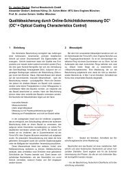


![Download PDF [5,37 MB] - MTU Aero Engines](https://img.yumpu.com/21945461/1/190x125/download-pdf-537-mb-mtu-aero-engines.jpg?quality=85)