PVA36 POWER VENT ADAPTOR KIT INSTALLATION ...
PVA36 POWER VENT ADAPTOR KIT INSTALLATION ...
PVA36 POWER VENT ADAPTOR KIT INSTALLATION ...

Create successful ePaper yourself
Turn your PDF publications into a flip-book with our unique Google optimized e-Paper software.
Included in this kit:<br />
W500-0431 Plate, restrictor<br />
W750-0127 Wire, 14” jumper<br />
W750-0197 Wire harness, unit (Electrical Box)<br />
W750-0211 Wire, thermostat<br />
W660-0078 Switch, Double Pole<br />
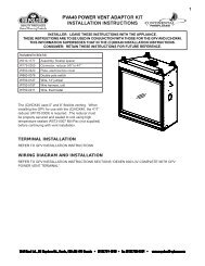
<strong>PVA36</strong> <strong>POWER</strong> <strong>VENT</strong> <strong>ADAPTOR</strong> <strong>KIT</strong><br />
<strong>INSTALLATION</strong> INSTRUCTIONS<br />
INSTALLER: LEAVE THESE INSTRUCTIONS WITH THE APPLIANCE.<br />
THESE INSTRUCTIONS ARE TO BE USED IN CONJUNCTION WITH THOSE FOR THE GPV AND THE<br />
APPLIANCE.<br />
THIS INFORMATION SUPERSEDES THAT IN THE APPLIANCE <strong>INSTALLATION</strong> INSTRUCTIONS.<br />
CONSUMER: RETAIN THESE INSTRUCTIONS FOR FUTURE REFERENCE.<br />
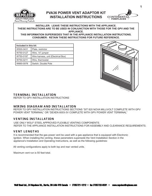
TERMINAL <strong>INSTALLATION</strong><br />
REFER TO GPV <strong>INSTALLATION</strong> INSTRUCTIONS<br />
BGD ILLUSTRATED<br />
WIRING DIAGRAM AND <strong>INSTALLATION</strong><br />
REFER TO GPV <strong>INSTALLATION</strong> INSTRUCTIONS SECTIONS “SIT 820 NOVA MILLIVOLT COMPLETE WITH GPV<br />
<strong>POWER</strong> <strong>VENT</strong> TERMINAL” OR “DEXEN 6003-3V COMPLETE WITH GPV <strong>POWER</strong> <strong>VENT</strong> TERMINAL”<br />
<strong>VENT</strong>ING <strong>INSTALLATION</strong><br />
USE ONLY WOLF STEEL APPROVED FLEXIBLE <strong>VENT</strong>ING COMPONENTS.<br />
REFER TO THE APPLIANCE <strong>INSTALLATION</strong> INSTRUCTIONS FOR ASSEMBLY AND CLEARANCE REQUIREMENTS.<br />
<strong>VENT</strong> LENGTHS<br />
It is recommended that the gas power vent be used with a gas appliance that is equipped with Electronic<br />
Ignition. When installing the venting, these parameters supersede the Vent Installation Section in the<br />
appliance's Installation and Operating Instructions, as well as the following guidelines:<br />
All venting confi gurations apply to both top and rear vented units.<br />
Maximum vent run is 50 feet total.<br />
Wolf Steel Ltd., 24 Napoleon Rd., Barrie, ON L4M 4Y8 Canada • (705)721-1212 • fax (705)722-6031 • www.napoleonfireplaces.com<br />
1
2<br />
SIMPLE REAR <strong>VENT</strong><br />
MAX H MIN H<br />
50 FEET 10 FEET<br />
SIMPLE TOP <strong>VENT</strong><br />
MAX H+V MIN H+V MAX ELBOWS<br />
50 FEET 10 FEET SIX 90°<br />
MULTI ELBOW<br />
Multi-elbow installations are possible up to a maximum of six 90°.<br />
MAX<br />
V1+V2+V3+<br />
H1+H2+H3<br />
MIN<br />
V1+V2+V3+<br />
H1+H2+H3<br />
MAX<br />
ELBOWS<br />
50 FEET 10 FEET SIX 90°<br />
DOWNWARD VERTICAL <strong>VENT</strong>ING<br />
Downward venting installations are only allowed when the<br />
appliances is set to Intermittent Pilot Ignition (I.P.I.) Electronic<br />
Ignition (E.I.). If an anti-condensation switch is being used,<br />
downward vertical venting is not allowed.<br />
MAX<br />
H1+H2+V<br />
MIN<br />
H1+H2+V<br />
MAX D MAX<br />
ELBOWS<br />
50 FEET 10 FEET 8 FEET SIX 90°<br />
Wolf Steel Ltd., 24 Napoleon Rd., Barrie, ON L4M 4Y8 Canada • (705)721-1212 • fax (705)722-6031 • www.napoleonfireplaces.com<br />
H 1
RESTRICTOR PLATE <strong>INSTALLATION</strong><br />
To ensure proper appliance operation, a restrictor plate (supplied) is<br />
required for either top or rear exit venting.<br />
IMPORTANT! The restrictor plate (supplied) has a knockout which<br />
must remain when used with the BGD/BCDV36. This knockout must<br />
be removed when installed in the GD/CDV36.<br />
1. Remove all obstructing components i.e.: brick panels, logs, baffle,<br />
etc.<br />
2. Install the restrictor plate as shown in Figure 6 over the opening.<br />
3. Re-install all the components removed in Step 1.<br />
<strong>VENT</strong>URI ADJUSTMENT<br />
The factory set openings must be reset according to the chart below:<br />
Closing the air shutter will cause a more yellow flame, but can lead to carboning.<br />
Opening the air shutter will cause a more blue flame, but can cause flame lifting<br />
from the burner ports. The flame may not appear yellow immediately; allow 15 to 30<br />
minutes for the final flame color to be established.<br />
AIR SHUTTER ADJUSTMENT MUST ONLY BE DONE BY A QUALIFIED<br />
INSTALLER!<br />
<strong>VENT</strong>URI ADJUSTMENT CHART<br />
FUEL GD/CDV36 BGD/BCDV36(CF)(G)<br />
NG 1/16” 0”<br />
LP 1/4” 1/8”<br />
KNOCKOUT<br />
RESTRICTOR PLATE<br />
TOP <strong>VENT</strong> BGD/BCDV36 ILLUSTRATED<br />
AIR<br />
SHUTTER<br />
OPENING<br />
W415-0765 / A / 11.24.09<br />
Wolf Steel Ltd., 24 Napoleon Rd., Barrie, ON L4M 4Y8 Canada • (705)721-1212 • fax (705)722-6031 • www.napoleonfireplaces.com<br />
3