concentric vent termination kit installation instructions
concentric vent termination kit installation instructions
concentric vent termination kit installation instructions

Create successful ePaper yourself
Turn your PDF publications into a flip-book with our unique Google optimized e-Paper software.
Advanced Heating and Hot Water Systems<br />
P.O. Box 429 ∙ 120 Braley Road ∙ East Freetown, MA 02717 ∙ 508-763-8071∙ Fax: 508-763-3769<br />
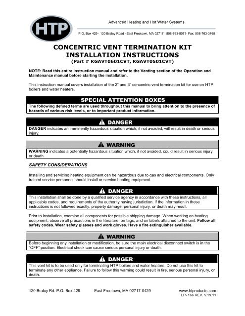
CONCENTRIC VENT TERMINATION KIT<br />
INSTALLATION INSTRUCTIONS<br />
(Part # KGAVT0601CVT, KGAVT0501CVT)<br />
NOTE: Read this entire instruction manual and refer to the Venting section of the Operation and<br />
Maintenance manual before starting the <strong>installation</strong>.<br />
This instruction manual covers <strong>installation</strong> of the 2” and 3” <strong>concentric</strong> <strong>vent</strong> <strong>termination</strong> <strong>kit</strong> for use on HTP<br />
boilers and water heaters.<br />
The following defined terms are used throughout this manual to bring attention to the presence of<br />
hazards of various risk levels, or to important product information.<br />
DANGER indicates an imminently hazardous situation which, if not avoided, will result in death or serious<br />
injury.<br />
WARNING indicates a potentially hazardous situation which, if not avoided, could result in serious injury<br />
or death.<br />
SAFETY CONSIDERATIONS<br />
Installing and servicing heating equipment can be hazardous due to gas and electrical components. Only<br />
trained service personnel should install or service heating equipment.<br />
This <strong>installation</strong> shall be done by a qualified service agency in accordance with these <strong>instructions</strong>, all<br />
applicable codes, and requirements of the authority having jurisdiction. If the information in these<br />
<strong>instructions</strong> is not followed exactly, property damage, personal injury, or death may result.<br />
Prior to <strong>installation</strong>, examine all components for possible shipping damage. When working on heating<br />
equipment, observe all precautions in the literature, on tags, and on labels attached to the unit. Follow all<br />
safety codes. Wear safety glasses and work gloves. Have a fire extinguisher available.<br />
Before beginning any <strong>installation</strong> or modification, be sure the main electrical disconnect switch is in the<br />
“OFF” position. Electrical shock can cause serious personal injury or death.<br />
This <strong>vent</strong> <strong>kit</strong> is to be used only for terminating HTP boilers and water heaters. Do not use this <strong>kit</strong> to<br />
terminate any other appliance. Failure to follow this warning could result in fire, serious personal injury, or<br />
death.<br />
120 Braley Rd. P.O. Box 429 East Freetown, MA 02717-0429 www.htproducts.com<br />
LP- 166 REV. 5.19.11
Field supplied pipe and fittings are required to complete the <strong>installation</strong>. The combustion air and <strong>vent</strong> pipe<br />
fittings must conform to American National Standards Institute (ANSI) and American Society for Testing<br />
and Materials (ASTM) standards D1785 (schedule-40 PVC), D2665 (PVC-DWV), D2441 (SDR-21 and<br />
SDR 26 PVC), D2661 (ABS DWV), or F628 (schedule-40 ABS). Pipe cement and primer must conform to<br />
ASTM standards D2564 (PVC) or D2235 (ABS).<br />
In Canada, construct all combustion air inlet and exhaust <strong>vent</strong> pipes for this unit with CSA or ULC certified<br />
schedule-40 PVC, PVC-DWV pipe and pipe cement.<br />
A. ROOF TERMINATION<br />
1. Determine the best location for the <strong>termination</strong> <strong>kit</strong>.<br />
NOTE: A roof <strong>termination</strong> is less susceptible to<br />
damage. It has reduced chances for intake<br />
contaminants and less visible <strong>vent</strong> vapors.<br />
2. Cut a hole in the roof 4” in diameter for 2”<br />
<strong>concentric</strong> <strong>vent</strong>, or 5” in diameter for 3” <strong>concentric</strong><br />
<strong>vent</strong> <strong>kit</strong>.<br />
3. Partially assemble <strong>concentric</strong> <strong>vent</strong> <strong>termination</strong> <strong>kit</strong>.<br />
a. Cement Y <strong>concentric</strong> fitting to larger<br />
diameter <strong>kit</strong> pipe (see Fig. 1).<br />
b. Cement rain cap to smaller diameter <strong>kit</strong><br />
pipe (see Fig. 1).<br />
Do not operate the appliance with rain cap removed. Re-circulation of combustion products may occur.<br />
Water may also collect inside larger combustion air pipe and flow to burner enclosure. Operating<br />
appliance without rain cap could result in product damage, improper operation, personal injury, or death.<br />
4. Install Y <strong>concentric</strong> fitting and pipe assembly<br />
through the hole in the roof and field supplied<br />
boot/flashing. NOTE: Do not allow insulation or<br />
other material to accumulate inside the pipe<br />
assembly when installing through the hole.<br />
5. Secure assembly to roof structure as shown in<br />
Fig. 4 using field supplied metal strapping or<br />
equivalent support material.<br />
NOTE: Ensure <strong>termination</strong> height is above the roof<br />
surface or anticipated snow level (1’ in USA or 1 ½’<br />
in Canada) as shown in Fig. 3.<br />
NOTE: If assembly is too short to meet height<br />
requirements, the two pipes supplied in the <strong>kit</strong> may<br />
be replaced by using same diameter, field supplied<br />
SDR-26 PVC (D2241) pipe. Do not extend<br />
dimension D more than 60” (See Fig. 2.) DO NOT<br />
USE COUPLINGS TO EXTEND PIPE.<br />
Figure 1 – Kit Components<br />
Figure 2 – Concentric Vent Dimensional Drawing<br />
NOTE: When shortening the length of the <strong>concentric</strong> <strong>vent</strong>, the inner pipe is longer than the outer pipe.<br />
Make sure you cut the same amount from each pipe. DO NOT make the pipes equal in length.<br />
2
6. Install rain cap and small<br />
diameter pipe assembly in roof<br />
penetration assembly. Ensure<br />
small diameter pipe is cemented<br />
and bottomed in Y <strong>concentric</strong><br />
fitting.<br />
7. Cement air inlet and exhaust<br />
<strong>vent</strong> pipes to <strong>concentric</strong> <strong>vent</strong><br />
<strong>termination</strong> assembly. See Fig.<br />
4 for proper pipe attachment.<br />
8. Operate boiler through a<br />
heating cycle to ensure air inlet<br />
and exhaust <strong>vent</strong> pipes are Figure 3 – Roof Termination<br />
properly connected to <strong>concentric</strong> <strong>vent</strong><br />
<strong>termination</strong> connections.<br />
NOTE: Multiple vertical <strong>vent</strong>ing is not<br />
allowed.<br />
It is very important to properly glue all joints.<br />
Failure to do so can result in property damage,<br />
serious personal injury, or death.<br />
B. SIDE WALL TERMINATION<br />
1. Determine the best location for the<br />
<strong>termination</strong> <strong>kit</strong>.<br />
a. Position <strong>termination</strong> <strong>kit</strong> where <strong>vent</strong><br />
Figure 4 – Roof Installation<br />
vapors will not damage plants, shrubs,<br />
air conditioning equipment, or the existing<br />
structure.<br />
b. Position <strong>termination</strong> <strong>kit</strong> so it will not be<br />
affected by wind (which may cause recirculation<br />
of combustion products), airborne leaves, light<br />
snow, or fertilizer.<br />
c. Position <strong>termination</strong> <strong>kit</strong> where it will not be<br />
subjected to damage from foreign objects, such<br />
as stones, balls, etc.<br />
d. Position <strong>termination</strong> <strong>kit</strong> where the <strong>vent</strong> noise<br />
will not be objectionable to abutters.<br />
2. Cut a hole in the sidewall 4” in diameter for 2”<br />
<strong>concentric</strong> <strong>vent</strong> <strong>kit</strong>, or 5” in diameter for 3” <strong>concentric</strong><br />
<strong>vent</strong> <strong>kit</strong>.<br />
3. Partially assemble <strong>concentric</strong> <strong>vent</strong> <strong>termination</strong> <strong>kit</strong>.<br />
a. Cement the Y <strong>concentric</strong> fitting to larger<br />
diameter <strong>kit</strong> pipe (see Fig. 1).<br />
b. Cement the rain cap to the smaller diameter<br />
<strong>kit</strong> pipe (see Fig. 1).<br />
Figure 5 – Sidewall Termination<br />
3
4. Install Y <strong>concentric</strong> fitting and pipe assembly through the hole.<br />
NOTE: Do not allow insulation or other materials to<br />
accumulate inside pipe assembly when installing<br />
through hole.<br />
5. Install rain cap and small diameter pipe assembly<br />
in Y <strong>concentric</strong> fitting and large pipe assembly.<br />
Ensure small diameter pipe is bottomed and<br />
cemented in Y <strong>concentric</strong> fitting.<br />
6. Secure assembly to structure using field supplied<br />
metal strapping or equivalent support material (see<br />
Fig. 6).<br />
NOTE: Ensure <strong>termination</strong> location clearance<br />
dimensions are as shown in Fig. 5.<br />
Figure 6 – Sidewall Attachment<br />
NOTE: If assembly needs to be extended to allow<br />
sidewall thickness requirement, the two pipes supplied in the <strong>kit</strong> may be replaced by using the same<br />
diameter, field supplied SDR-26 (D2241) pipe. Do not extend Dimension D to more than 60” (see Fig. 2).<br />
DO NOT USE COUPLINGS TO EXTEND PIPE.<br />
7. Cement air inlet and exhaust <strong>vent</strong> pipes to <strong>concentric</strong><br />
<strong>vent</strong> <strong>termination</strong> assembly. See Fig. 6 for proper pipe<br />
attachment.<br />
8. Operate boiler/heater through a heating cycle to ensure<br />
air inlet and exhaust <strong>vent</strong> pipes are properly connected to<br />
<strong>concentric</strong> <strong>vent</strong> <strong>termination</strong> connections.<br />
9. Allow 8” center-to-center distance between <strong>concentric</strong><br />
<strong>vent</strong> <strong>termination</strong>s on multiple boiler <strong>installation</strong>s (see Fig.<br />
7).<br />
Figure 7 – Multiple Boiler Installations<br />
4<br />
LP-166 Rev. 5.19.11