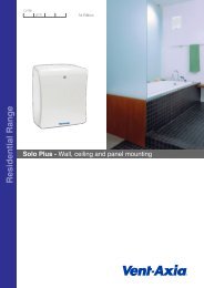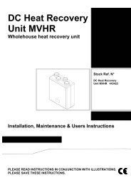
COMBINED STORAGE AND CONVECTOR HEATER - Vent-Axia
COMBINED STORAGE AND CONVECTOR HEATER - Vent-Axia
COMBINED STORAGE AND CONVECTOR HEATER - Vent-Axia

You also want an ePaper? Increase the reach of your titles
YUMPU automatically turns print PDFs into web optimized ePapers that Google loves.
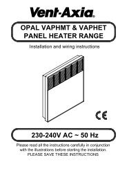
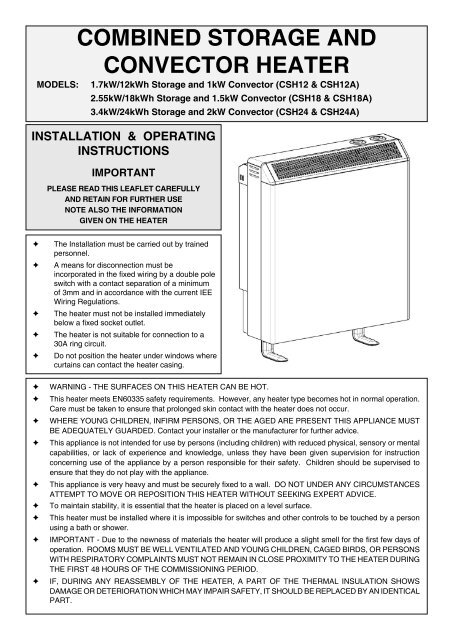
<strong>COMBINED</strong> <strong>STORAGE</strong> <strong>AND</strong><br />
<strong>CONVECTOR</strong> <strong>HEATER</strong><br />
MODELS: 1.7kW/12kWh Storage and 1kW Convector (CSH12 & CSH12A)<br />
2.55kW/18kWh Storage and 1.5kW Convector (CSH18 & CSH18A)<br />
3.4kW/24kWh Storage and 2kW Convector (CSH24 & CSH24A)<br />
INSTALLATION & OPERATING<br />
INSTRUCTIONS<br />
IMPORTANT<br />
PLEASE READ THIS LEAFLET CAREFULLY<br />
<strong>AND</strong> RETAIN FOR FURTHER USE<br />
NOTE ALSO THE INFORMATION<br />
GIVEN ON THE <strong>HEATER</strong><br />
The Installation must be carried out by trained<br />
personnel.<br />
A means for disconnection must be<br />
incorporated in the fi xed wiring by a double pole<br />
switch with a contact separation of a minimum<br />
of 3mm and in accordance with the current IEE<br />
Wiring Regulations.<br />
The heater must not be installed immediately<br />
below a fi xed socket outlet.<br />
The heater is not suitable for connection to a<br />
30A ring circuit.<br />
Do not position the heater under windows where<br />
curtains can contact the heater casing.<br />
WARNING - THE SURFACES ON THIS <strong>HEATER</strong> CAN BE HOT.<br />
This heater meets EN60335 safety requirements. However, any heater type becomes hot in normal operation.<br />
Care must be taken to ensure that prolonged skin contact with the heater does not occur.<br />
WHERE YOUNG CHILDREN, INFIRM PERSONS, OR THE AGED ARE PRESENT THIS APPLIANCE MUST<br />
BE ADEQUATELY GUARDED. Contact your installer or the manufacturer for further advice.<br />
This appliance is not intended for use by persons (including children) with reduced physical, sensory or mental<br />
capabilities, or lack of experience and knowledge, unless they have been given supervision for instruction<br />
concerning use of the appliance by a person responsible for their safety. Children should be supervised to<br />
ensure that they do not play with the appliance.<br />
This appliance is very heavy and must be securely fi xed to a wall. DO NOT UNDER ANY CIRCUMSTANCES<br />
ATTEMPT TO MOVE OR REPOSITION THIS <strong>HEATER</strong> WITHOUT SEEKING EXPERT ADVICE.<br />
To maintain stability, it is essential that the heater is placed on a level surface.<br />
This heater must be installed where it is impossible for switches and other controls to be touched by a person<br />
using a bath or shower.<br />
IMPORTANT - Due to the newness of materials the heater will produce a slight smell for the fi rst few days of<br />
operation. ROOMS MUST BE WELL VENTILATED <strong>AND</strong> YOUNG CHILDREN, CAGED BIRDS, OR PERSONS<br />
WITH RESPIRATORY COMPLAINTS MUST NOT REMAIN IN CLOSE PROXIMITY TO THE <strong>HEATER</strong> DURING<br />
THE FIRST 48 HOURS OF THE COMMISSIONING PERIOD.<br />
IF, DURING ANY REASSEMBLY OF THE <strong>HEATER</strong>, A PART OF THE THERMAL INSULATION SHOWS<br />
DAMAGE OR DETERIORATION WHICH MAY IMPAIR SAFETY, IT SHOULD BE REPLACED BY AN IDENTICAL<br />
PART.
INSTALLATION INSTRUCTIONS<br />
The heater will arrive<br />
separately from its<br />
storage bricks, the<br />
following bricks will<br />
be required.<br />
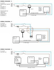
Circuit Diagram<br />
PREPARATION<br />
CSH12 & CSH12A - 8 bricks<br />
CSH18 & CSH18A - 12 bricks<br />
CSH24 & CSH24A - 16 bricks<br />
WARNING - This appliance must be earthed.<br />
Only heat resisting cable (min. rating T85) should be used.<br />
The wires in the mains cable will be coloured as follows;<br />
GREEN & YELLOW - EARTH<br />
BLUE - NEUTRAL<br />
BROWN - LIVE<br />
SUGGESTED FIXINGS<br />
SOLID BRICK/BLOCK - No. 10 Size plastic inserts, 8mm<br />
drill bit. Drill hole 15mm deeper than plastic insert length.<br />
PLASTERBOARD - If possible locate studding and use<br />
No. 10 woodscrews directly into the wood, otherwise M5<br />
rawlplug intersets are suitable.<br />
NOTE:FOR ALL OTHER WALL TYPES (e.g. Timer frame<br />
and follow concrete) SEEK SPECIALIST ADVICE.<br />
1.<br />
FIXING ASSEMBLY<br />
ENSURE THAT FIXING KIT <strong>AND</strong> FEET HAVE BEEN<br />
LOCATED BEFORE DISPOSING OF PACKAGING.<br />
2. Fit the feet with the open end of the foot to the front<br />
of the heater. Secure each foot using the two taptite<br />
screws provided.<br />
2.<br />
3.<br />
SH(A) MODELS ONLY - The Room Sensor is located<br />
at the rear of the right hand side of the heater. Carefully<br />
slide the sensor plate down from its transit position to its<br />
operational position.<br />
3.<br />
4. Place the heater on its feet and in the desired position<br />
against the wall. Ensure the heater is based on a fi rm level surface<br />
at least 75mm from any end wall and at least 250mm below any<br />
shelf or similar projection. Cut away any gripper rod or carpet<br />
which would prevent the heater sitting fi rmly on the fl oor.<br />
4.<br />
5. Mark the position of the two outside corners of the wall<br />
bracket with the heater pushed tight against the wall. Remove<br />
the wall bracket from the heater by removing the screw at each<br />
end. Place the heater to one side and reposition the bracket<br />
against the wall using the corner marks for alignment.<br />
Four fi xing positions must be chosen for the 24, three for<br />
the 18 and two for the 12. Mark the positions for the fi xing<br />
holes - two at the extreme ends and the others spaced evenly<br />
between them. Remove the bracket from the wall, drill the<br />
holes in the positions marked, and insert suitable fi xings<br />
previously described. Secure the wall bracket to the wall.<br />
5.<br />
6. If mains connection is to be made from the left hand<br />
side, at this point the mains lead must be secured to the<br />
back of the heater using ties provided in the fi xing kit.<br />
6.<br />
Transit Position Operational Position<br />
7. THE FOLLOWING MUST BE APPLIED WHEN<br />
FIXING THE <strong>HEATER</strong> TO THE WALL BRACKET<br />
i) If no skirting board is present secure the heater through<br />
the wall bracket slots closest to the wall.<br />
ii) If 100mm (4in.) skirting is present secure the heater<br />
through the outer slots.<br />
iii) If skirting taller than 150mm (6in.) is present this must<br />
be reduced to 150mm (6in.) over the entire width of the<br />
heater plus 25mm (1in.) at each end.<br />
Do not fully tighten these screws until the bricks are loaded<br />
into the heater as some settling of the heater may occur.<br />
NOTE: NEVER REMOVE THESE SCREWS WITHOUT<br />
FIRST UNLOADING THE <strong>HEATER</strong>.
7.<br />
8. Remove the front panel by removing the two self tapping<br />
screws along its bottom edge. With hands positioned<br />
on each side of the panel, lift upwards to unhook the top edge<br />
whilst pressing down on the top panel with your thumbs.<br />
Ensure the convector element is not damaged when placing<br />
this panel to one side.<br />
8.<br />
9. Remove the inner front panel be removing the screws<br />
along its top and sides. As the front insulation is<br />
attached care must be taken when lifting this panel from<br />
the heater and placing it to one side. Remove the internal<br />
packing by sliding it up and off the elements taking care not<br />
to damage the insulation.<br />
9. 10.<br />
10. Remove one element to allow access for the back row<br />
of bricks. On the 24 remove the element to the right<br />
of centre, on the 18 remove the central element, on the 12<br />
the left hand element should be removed.<br />
Loosen the two screws securing the element tails in the ceramic<br />
connector block, and lift the element up and out of the heater.<br />
11. Carefully fi t the bottom row of the back layer of bricks<br />
placing the two end bricks in position fi rst with the<br />
recess towards the element. Fit the top row of bricks also<br />
with the recess towards the element.<br />
12. Refi t the element which has been removed by feeding<br />
the tails down through the hole in the base insulation and<br />
into the connector block. Ensure the element is fully pushed<br />
home then securely tighten the two screws in the block.<br />
12.<br />
13. Fit the front layer of bricks again with the recess towards<br />
the element. The complete core will comprise:<br />
12 - 2 x 4 Brick Columns<br />
18 - 3 x 4 Brick Columns<br />
24 - 4 x 4 Brick Columns<br />
14. Replace the inner front complete with insulation by<br />
locating its bottom edge behind the front lip of the chassis<br />
and inserting retaining screws along the top and both sides.<br />
15. Check that the fl ap mechanism operates freely on its<br />
hinges and that with the output control set to 1 the<br />
fl ap is correctly seated in its closed position.<br />
16. Connection of Supply to Storage - Feed the mains<br />
cable through the cable clamp and make connections<br />
as marked on the heater. Pull back any slack through the<br />
clamp and tighten clamping screw.<br />
WARNING - This appliance must be earthed.<br />
16.<br />
RESTRICTED SUPPLY<br />
17. Connection of supply to Convector is through a<br />
cable clamp in the case of the front panel.<br />
Connect the wires as detailed below, pull back any slack<br />
through the cable clamp and tighten clamping screws, see<br />
picture 16.<br />
17.<br />
UNRESTRICTED<br />
SUPPLY<br />
18. Replace the outer<br />
front panel and grille<br />
by hooking the grille into<br />
its retaining slot on the top<br />
panel and lowering it into<br />
position. Secure the front<br />
panel with two self tapping<br />
screws.<br />
18.<br />
19. Check that the screws securing the heater to the wall<br />
bracket have been fully tightened.<br />
IT IS ESSENTIAL THAT ALL SCREWS ARE REPLACED<br />
TO ENSURE EARTH CONTINUITY.<br />
Once installed do not attempt to reposition the heater without<br />
fi rst obtaining the services of a competent electrician.
OPERATING INSTRUCTIONS<br />
OPERATION<br />
Your CSH(A) heater combines the economy of a storage<br />
heater with the convenience of a convector heater.<br />
The storage heater takes in energy, when electricity tariffs<br />
are low and dissipates it when tariffs are normal.<br />
The convector heater provides an instant boost on<br />
demand from normal tariff electricity.<br />
SAFETY INSTRUCTIONS<br />
1. <strong>Vent</strong>ilate rooms well during commissioning.<br />
2. Do not move the heater in any way once installed without the<br />
services of a competent electrician.<br />
3. Do not cover the heater with clothing etc. at any time or position<br />
furniture close to or against the heater.<br />
4. Ensure a clearance of at least 150mm between heaters and<br />
curtains.<br />
5. Should your heater fail to operate either employ the services<br />
of a competent electrician or contact your supplier.<br />
ALSO REFER TO COVER PAGE<br />
COMMISSIONING<br />
Set both the Input Control and the Output Control to 6 and<br />
leave the heater for 48 hours.<br />
Following the commissioning period adjust the controls as<br />
stated below.<br />
SETTING THE CONTROLS<br />
The storage controls are located on the top panel. The<br />
convector controls are located at the top of the front panel’s<br />
right side.<br />
CONTROL FUNCTIONS<br />
THE INPUT CONTROL<br />
For models CSH12A, CSH18A and CSH24A only:<br />
This heater is fi tted with a user adjustable automatic input control which<br />
varies the charge taken in response to weather conditions taking into<br />
account the amount of energy already stored in the heater.<br />
Set at 6 the heater takes maximum charge and at 1 the heater takes a<br />
minimum charge at any room temperature. The casing of the heater,<br />
particularly in late evening, may feel cool, this is quite normal. The input<br />
control may require a few days experimentation before your comfort<br />
level is established.<br />
Initially set the control to 4, the following evening if the room is too warm<br />
reduce to 3 or if it is too cool increase to 5. On subsequent evenings<br />
adjust by half divisions until our comfort level is achieved.<br />
Having established the setting the input will automatically carry the<br />
amount of heat stored to compensate for weather variations.<br />
For models CSH12, CSH18 and CSH24 only:<br />
Initially set the input to 4. If the heater does not maintain a<br />
satisfactory room temperature the following day this setting should<br />
be increased. Conversely if the room temperature is too high this<br />
setting should be reduced.<br />
The input control should only require seasonal adjustments.<br />
THE OUTPUT CONTROL<br />
Most of the stored heat is radiated from the casing during the<br />
discharge period. However, some of the heat is emitted through<br />
the grille at the top of the heater and this additional heat (boost)<br />
is regulated by the Output Control.<br />
With this set to 6 the boost begins in the early afternoon. Turning<br />
the control towards 1 will progressively delay the commencement<br />
of the boost. At 3 the boost will start in the evening. Once set, the<br />
boost will repeat itself automatically day after day.<br />
If no boost is required, e.g. when the room will be unoccupied<br />
for along period, set the Output Control to 1. With the control in<br />
this position, the heater will take in less energy during the next<br />
charging up period.<br />
<strong>CONVECTOR</strong> <strong>HEATER</strong><br />
<strong>CONVECTOR</strong> <strong>HEATER</strong> CONTROLS<br />
The convector is selected by an on/off rocker switch which<br />
illuminates when switched on ‘1’. With the switch on, the convector<br />
element shall be cycled on and off by the room thermostat. With<br />
the switch off “0” the convector will not run. The room thermostat<br />
knob is marked 1 to 5. The higher the setting number chosen, the<br />
higher the level at which the room temperature will be controlled.<br />
Your comfort level can easily be established by gradually adjusting<br />
the thermostat until the required room temperature is maintained.<br />
CLEANING<br />
To maintain the appearance of the heater wipe occasionally with<br />
a dry cloth when the heater is cool.<br />
Do not use abrasive powders or furniture polish.<br />
Discoloration of wall fi nishes can sometimes occur immediately<br />
above a storage heater due to the properties of some paints and<br />
decorating materials or the presence of environmental impurities<br />
in the air (such as soot or incense generated for the burning of<br />
candles, etc.).<br />
RECYCLING<br />
For electrical products sold within the European<br />
Community. At the end of the electrical products useful<br />
life it should not be disposed of with household waste.<br />
Please recycle where facilities exist. Check with your<br />
Local Authority or retailer for recycling advice in your country.<br />
438941A SUPPLIED BY APL 87659 : 1 08.2008