Die Cast Chill Vents - DME
Die Cast Chill Vents - DME
Die Cast Chill Vents - DME

Create successful ePaper yourself
Turn your PDF publications into a flip-book with our unique Google optimized e-Paper software.
1<br />
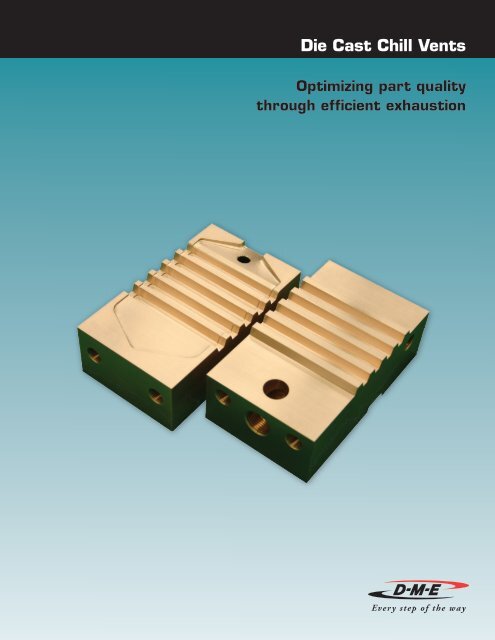
<strong>Die</strong> <strong>Cast</strong> <strong>Chill</strong> <strong>Vents</strong><br />
Optimizing part quality<br />
through efficient exhaustion<br />
1
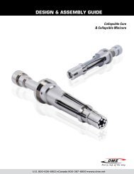
<strong>Chill</strong> Vent Features & Benefits<br />
D-M-E<br />
<strong>Die</strong> <strong>Cast</strong> <strong>Chill</strong> <strong>Vents</strong><br />
• <strong>Chill</strong> vents are often used with permanent molds for die casting light<br />
metals such as aluminum and magnesium. The chill vent functions as a<br />
means of efficiently exhausting residual air and/or gas from the inside to<br />
the outside of a die cast mold cavity.<br />
• <strong>Chill</strong> vents minimize the spouting of molten metal and reduce flashing<br />
when charging molten metal into the die cavity.<br />
• If residual air and/or gas remains in the die cavity, the result may be gas<br />
holes in the castings that degrade product quality.<br />
• Gas exhaust passage design is generally shaped in a zigzag manner to<br />
ensure that after the gas has been exhausted outside of the chill vent,<br />
the molten metal will be chilled in the zigzag passage before it is flashed<br />
outside of the permanent mold. However, since molten metal flows<br />
under high pressure, it is difficult to completely prevent flashing even by<br />
increasing the length of the chill vent.<br />
Why <strong>Chill</strong> <strong>Vents</strong>?<br />
• Tool steels, although high in hardness, have low thermal conductivity, and, therefore, cannot rapidly remove heat from nonsolidified<br />
molten metal before flashing occurs.<br />
• Since both high hardness and superior thermal conductivity are critical requisites in achieving accelerated cooling of molten metal<br />
under high pressure, it has been considered that copper alloys would provide superior thermal conductivity. However, few copper<br />
alloys provide both thermal conductivity and hardness in combination sufficient to withstand the pressure that results in die casting<br />
molten metal.<br />
• Additionally, copper alloys are generally difficult to use for molds brought into contact with molten metal because they are easily<br />
dissolved by light metal alloys compared to tool steel.<br />
• Conventional chill vent material has been predominantly made of tool steel, typically the same as the permanent mold cavity. It is<br />
necessary that the chill vent be as hard as the permanent mold cavity due to the high-pressure condition that develops when the<br />
molten metal is charged into the chill vent.<br />
Why Beryllium Copper?<br />
• Only one alloy, beryllium copper, can provide both the hardness and<br />
thermal conductive properties required for use as a chill vent in<br />
aluminum and/or magnesium die casting.<br />
• Beryllium copper also provides the benefit of causing a passivestate<br />
oxide film to be formed on the surface of the chill vent, thereby<br />
preventing dissolution by light metal alloys.<br />
• These factors provide an effective means of exhausting air and gases<br />
outside the mold without being dissolved while chilling the molten<br />
metal before flashing occurs.<br />
• As a further consideration, the addition of water cooling pipes in<br />
the chill vent will serve to improve the overall cooling power which<br />
can result in a shortening of the length of the gas exhaust passage,<br />
leading to a smaller chill vent, thus increasing die space.<br />
U.S. 800-626-6653 n Canada 800-387-6600 n www.dme.net<br />
2
3<br />
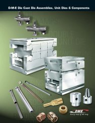
Reduces Porosity<br />
D-M-E<br />
<strong>Die</strong> <strong>Cast</strong> <strong>Chill</strong> <strong>Vents</strong><br />
• Large vent gap promotes better venting<br />
(3-8 times better than conventional H13)<br />
• Longer effective vacuum time since the metal always freezes in the vent<br />
(Avoids the time lag caused by the vacuum valve)<br />
Cuts Downtime & Maintenance Costs<br />
with Vacuum Machine<br />
D-M-E <strong>Chill</strong> <strong>Vents</strong> can be used with a vacuum machine in place of the vacuum<br />
valve, reducing maintenance cost, downtime and porosity.<br />
• Protects vacuum system from molten aluminum<br />
– Vacuum valve can be replaced with a D-M-E chill vent<br />
– High solidification rate prevents aluminum from entering the vacuum equipment<br />
• Easy to use<br />
– Its simple structure requires no special knowledge or technique<br />
Minimizes Sticking<br />
• Copper doesn’t promote a chemical reaction with aluminum compared with H13<br />
• The thicker waffle from the large vent gap is easily removed, and is higher<br />
quality scrap<br />
• Low surface temperature due to high conductivity further avoids sticking<br />
Compatible with Vacuum Machine<br />
Saves <strong>Die</strong> Space<br />
The size of vent area can be half that needed for H13 due to higher solidification performance. This reduce the total die area.<br />
Why D-M-E <strong>Chill</strong> <strong>Vents</strong>?<br />
1) Made of Hard Copper Alloy (Beryllium Copper)<br />
• No reaction with aluminum No “Sticking”<br />
• *H13 reacts with aluminum Causes “Sticking”<br />
2) High Thermal Conductivity<br />
*Beryllium copper is seven times more conductive than H13 for faster<br />
chilling and faster solidification of the molten alloy.<br />
*Allows a larger vent gap (1.4 to 1.8 times larger than H13) for better gas<br />
exhaustibility (3 to 8 times more than H13) to reduce porosity!<br />
Vent gap<br />
H13 0.020”(0.5 mm)<br />
D-M-E<br />
0.028”– 0.043” (0.7–1.1 mm)<br />
D-M-E <strong>Chill</strong>-Vent installed<br />
in place of vacuum valve<br />
Overflow<br />
<strong>Cast</strong>ing<br />
Product<br />
(Plunger)<br />
U.S. 800-626-6653 n Canada 800-387-6600 n www.dme.net<br />
Air<br />
Vacuum System<br />
Vacuum Pump<br />
(<strong>Die</strong>)<br />
Solidify Eruption!<br />
D-M-E C/V H13 C/V<br />
Product Availability<br />
• Copper Alloy (Beryllium Copper)<br />
supplied by NGK Beryl Co./<br />
NGK Metals Corp.<br />
• All copper alloy recommended<br />
for A390, zinc and all alloys<br />
• Vacuum/non-vacuum type<br />
• Custom designs are welcome
D-M-E<br />
<strong>Die</strong> <strong>Cast</strong> <strong>Chill</strong> <strong>Vents</strong><br />
IMPORTANT SAFETY INFORMATION<br />
DANGER<br />
BEFORE USING THIS PRODUCT, REFER TO IMPORTANT SAFETY INFORMATION AT MANUFACTURER’S WEBSITE:<br />
http://www.ngkmetals.com/index.cfm/m/19<br />
ADDITIONAL INFORMATION MAY BE FOUND AT:<br />
http://www.osha.gov/dts/hib/hib_data/hib19990902.html<br />
READ ALL INSTRUCTIONS BEFORE HANDLING THIS PRODUCT INCLUDING THE MSDS.<br />
INSTALLATION INSTRUCTIONS<br />
ITEM<br />
NUMBER<br />
POCKET DIMENSIONS<br />
“Xp”<br />
+ 0.030 / + 0.010<br />
(+ 0.0012 / + 0.0004”)<br />
“Yp”<br />
+ 0.030 / + 0.010<br />
(+ 0.0012 /+ 0.0004”)<br />
VSCL7US 135.000 (5.3150”) 80.000 (3.1496”)<br />
VLCL7US 175.000 (6.8998”) 90.000 (3.5433”)<br />
VECL7US 185.000 (7.2835”) 100.000 (3.9370”)<br />
Dimensions shown are in millimeters (inches).<br />
ITEM<br />
NUMBER<br />
VSCL7US<br />
VLCL7US<br />
VECL7US<br />
“X“<br />
+ 0 / – 0.06<br />
(+ 0 / – 0.003”)<br />
135.00<br />
(5.315”)<br />
175.00<br />
(6.890”)<br />
185.00<br />
(7.283”)<br />
“Y”<br />
+ 0 / – 0.05<br />
(+ 0 / – 0. 02”)<br />
80.00<br />
(3.150”)<br />
90.00<br />
(3.543”)<br />
100.00<br />
(3.937”)<br />
THIS INSTRUCTION IS TO BE PROVIDED TO THE END USER.<br />
”Z”<br />
+ 0.05 / – 0<br />
(+ 0.002 / – 0”)<br />
50.00<br />
(1.968”)<br />
50.00<br />
(1.968”)<br />
50.00<br />
(1.968”)<br />
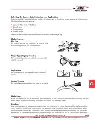
CHILL VENT POCkET DETAIL<br />
Zp<br />
“Zp”<br />
SEE<br />
POCKET<br />
NOTES<br />
POCkET NOTES:<br />
• Perpendicularity and parallelism of pockets must be machined such that <strong>Chill</strong> Vent insert<br />
halves mate after installation without gaps between insert halves.<br />
• Corner radii of <strong>Chill</strong> Vent insert pockets are to be machined to suit dimensions shown.<br />
• All surfaces of pocket to have a surface finish no greater than 0.8 μm (micrometers).<br />
Check for burrs.<br />
• For Zp, use shim pack to accommodate flushness. Flushness tolerance must be + 0.05/– 0<br />
(+ 0.002/– 0”). Zp must be greater than Z (applies to both insert halves and pockets).<br />
CHILL VENT DIMENSIONS<br />
Ø D1<br />
+ 0.02 / – 0<br />
(+ 0.00 / – 0”)<br />
Yp<br />
10.00<br />
(0.394”)<br />
10.00<br />
(0.394”)<br />
10.00<br />
(0.394”)<br />
”P”<br />
26.0<br />
(1.02”)<br />
30.0<br />
(0.18”)<br />
35.0<br />
(1.38”)<br />
”k”<br />
+/– 0.046<br />
(+/– 0.0018”)<br />
55.00<br />
(2.165”)<br />
65.00<br />
(2.559”)<br />
65.00<br />
(2.559”)<br />
U.S. 800-626-6653 n Canada 800-387-6600 n www.dme.net<br />
”B”<br />
40.0<br />
(1.575”)<br />
60.0<br />
(2.36”)<br />
60.0<br />
(2.36”)<br />
SCREW<br />
THREAD<br />
5/16 – 18<br />
UNC<br />
1/2 – 13<br />
UNC<br />
1/2 – 13<br />
UNC<br />
“L1”<br />
20.00<br />
(0.787”)<br />
25.00<br />
(0.984”)<br />
25.00<br />
(0.984”)<br />
Xp<br />
(Example pocket for<br />
one half of <strong>Chill</strong> Vent<br />
Insert Assembly)<br />
”F1 “<br />
× THREAD<br />
DEPTH<br />
1/2 – 14<br />
× 10.0<br />
3/4 – 14<br />
× 12.0<br />
3/4 – 14<br />
× 12.0<br />
NPT<br />
(0.39)<br />
NPT<br />
(0.47)<br />
NPT<br />
(0.47)<br />
Ø D2 “T”<br />
18.00<br />
(0.709”)<br />
23.00<br />
(0.906”)<br />
23.00<br />
(0.906”)<br />
45.00<br />
(1.772”)<br />
45.00<br />
(1.772”)<br />
50.00<br />
(1.968”)<br />
Yp<br />
4
5<br />
CHILL VENT INSERT – DETAIL<br />
TOP HALF<br />
NOTE: Dimensions shown are in millimeters (inches).<br />
13.6 (2)<br />
(.54)<br />
SHARP<br />
CORNER<br />
INSTALLATION NOTES:<br />
• 10mm DIN Ejector Pin to be used with this<br />
product<br />
• Key slots provided on product as shown.<br />
Customer is responsible for keying product.<br />
• Tap threads are provided in product for<br />
retaining screws. Customer to supply screws.<br />
• Customer to supply NPT pipe fittings.<br />
High temperature pipe thread sealant is<br />
recommended to be used with this product.<br />
• Once installed, <strong>Chill</strong> Vent insert halves<br />
must align properly to achieve good seal-off<br />
between mating surfaces. Use a blue-off<br />
compound to check for proper fit. Adjust<br />
shim pack accordingly during installation<br />
until desired mating seal-off is achieved.<br />
NOTICE:<br />
D-M-E shall not be liable for misuse<br />
or failure to follow the enclosed<br />
instructions and specifications. D-M-E<br />
hereby disclaims all implied warranties,<br />
including merchantability and fitness<br />
for a particular purpose. In no event<br />
shall D-M-E be responsible for loss of<br />
use, revenue or profit, or for incidental<br />
or consequential damages.<br />
D-M-E<br />
<strong>Die</strong> <strong>Cast</strong> <strong>Chill</strong> <strong>Vents</strong><br />
Z<br />
T<br />
K<br />
BOTTOM HALF<br />
20.0<br />
(.79)<br />
5.00<br />
(.197)<br />
5.00 REF<br />
(.197)<br />
22.0<br />
(.87)<br />
R3.0<br />
(.12)<br />
20.00 ± 0.08<br />
(.787 ± .002)<br />
SCREW<br />
THREAD<br />
U.S. 800-626-6653 n Canada 800-387-6600 n www.dme.net<br />
B<br />
SHARP<br />
CORNER<br />
1.0 x 45 DEG<br />
(. 04)<br />
15.00 ± 00.06<br />
(.591 ± .002)<br />
T<br />
X<br />
20.0<br />
(.79)<br />
L1<br />
0.5 (Max) × 45 DEG (.12)<br />
R0.51<br />
(. 020)<br />
K<br />
Ø D1<br />
Ø D2<br />
X<br />
6.00<br />
(.236)<br />
B<br />
P<br />
P<br />
F1<br />
1/4 – 18 NPT<br />
Thread Depth<br />
– 8.0 (.32)<br />
(2)<br />
Y<br />
18.6<br />
(.73)<br />
20.0<br />
(.79)<br />
20.00±0.06<br />
(.787±002)<br />
SCREW<br />
THREAD<br />
P P<br />
20.0<br />
(.79)<br />
Y<br />
Z<br />
1/4 –18 NPT<br />
Thread Depth<br />
– 8.0 (.32)<br />
(2)
D-M-E, an essential resource to the<br />
customers it serves worldwide, offers<br />
the industry’s broadest range of<br />
market-leading products, unsurpassed<br />
knowledge and expertise, a global<br />
logistics infrastructure that ensures<br />
speed and accuracy, and a support<br />
organization unrivaled for its ability<br />
to assist customers when and where<br />
they need it. A complete line of unit<br />
dies, die components, hot runner<br />
systems, control systems, mold bases,<br />
MUD quick-change mold systems,<br />
mold components, moldmaking and<br />
molding supplies, cold runner systems<br />
for elastomers, and technical services<br />
helps customers compete every step of<br />
the way.<br />
See the complete line of D-M-E die cast die assemblies, unit dies and components at<br />
www.dme.net/dme/resources/catalog.html<br />
or D-M-E call Customer Service to request a printed catalog.<br />
World Headquarters<br />
D-M-E Company<br />
29111 Stephenson Highway<br />
Madison Heights, MI 48071<br />
800-626-6653 toll-free tel<br />
248-398-6000 tel<br />
888-808-4363 toll-free fax<br />
www.dme.net web<br />
sales@dme.net e-mail<br />
D-M-E of Canada, Ltd.<br />
6210 Northwest Drive<br />
Mississauga, Ontario<br />
Canada L4V 1J6<br />
800-387-6600 toll-free tel<br />
905-677-6370 tel<br />
800-461-9965 toll-free fax<br />
dme_canada@dme.net e-mail<br />
D-M-E Europe<br />
D-M-E Belgium C.V.B.A.<br />
Industriepark Noord<br />
B-2800 Mechelen<br />
Belgium<br />
32-15-215011 tel<br />
32-15-218235 fax<br />
sales@dmeeu.com e-mailCV-8/09