A SILICON STRIP VERTEX DETECTOR FOR THE MARK II ...
A SILICON STRIP VERTEX DETECTOR FOR THE MARK II ...
A SILICON STRIP VERTEX DETECTOR FOR THE MARK II ...

You also want an ePaper? Increase the reach of your titles
YUMPU automatically turns print PDFs into web optimized ePapers that Google loves.
_P_<br />
SLAC - PUB - 4400<br />
SCIPP87/89<br />
August 1987<br />
(N)<br />
A <strong>SILICON</strong> <strong>STRIP</strong> <strong>VERTEX</strong> <strong>DETECTOR</strong> <strong>FOR</strong> <strong>THE</strong><br />
<strong>MARK</strong> <strong>II</strong> EXPERIMENT AT <strong>THE</strong> SLAC LINEAR COLLIDER*<br />
ALAN LITKE, CHRIS ADOLPHSEN,<br />
ANDREAS S. SCHWARZ, MICHAL TURALA t and ALAN STEINER<br />
Santa Cruz Institute for Particle Physics<br />
University of California, Santa Cruz, CA 95061<br />
ALAN BREAK~TONE AND SHERWOOD PARKER<br />
University of Hawaii, Honolulu, HI 96822<br />
VERA LATH<br />
Stanford Linear Accelerator Center<br />
Stanford University, Stanford, CA Qd305<br />
BRUCE BARNETT, PAUL DAUNCEY, AND DAVID DREWER<br />
Johns Hopkins University, Baltimore, MD 21218<br />
Abstract<br />
The design and status of a silicon strip vertex detector for the Mark <strong>II</strong> ex-<br />
periment at the SLAC Linear Collider are described.<br />
Presented at the International Conference on Advances in Experimental<br />
Methods for Colliding Beam Physics, March Q-19, 1987<br />
- -- L..<br />
* Work rapported by the Department of Energy, Contracts DE-AC03-76SF00515<br />
DlGAA03-76SFOOO34 and DELAC03-83ER-40103, and the National Science Foundation<br />
grant 84 04 562.<br />
t Viaitor from the In&itate of Nuclear Phyrics, Krakow, Poland
i ,;’ 1; Introduction<br />
. In the near future the Mark <strong>II</strong> experiment will begin the study of the Z”<br />
-1.<br />
at the SLAC Linear Collider (SLC). In order to study the decays of the Z” to<br />
short-lived particles, we are developing a silicon strip vertex detector (SSVD) for<br />
use in the Mark <strong>II</strong> detector. The physics motivation and preliminary design for<br />
the SSVD have been given in ref. [l]; in this paper we will describe the present<br />
design and status of this device.<br />
We note that the SLC is a very good place for a high precision vertex detector.<br />
First and foremost, there is the potential for wonderful physics, as the Mark <strong>II</strong><br />
experiment at the SLC is expected to provide the first detailed look at the 2”.<br />
Second, the SLC is designed to have a small beam spot (u=,~ = 2 pm; a, = 1<br />
mm) which should allow for a precise localization of the primary vertex. Third,<br />
there will be a small beam pipe radius (r = 2.6 cm). A vertex detector placed<br />
just outside the beam pipe will have a small lever arm for track extrapolation and<br />
multiple scattering, and thus, potentially, a small error on the impact parameter<br />
measurement. Moreover, a small radius device needs to cover only a relatively<br />
small area, which is a feature of particular importance for a silicon detector. (The<br />
SSVD will cover a total area of 500 cm2 in three layers). Finally, the low beam<br />
crossing frequency of the SLC (5180 Hz) implies a low duty cycle and therefore<br />
low power consumption for the read-out electronics.<br />
We further note that the SSVD is complementary to the Mark <strong>II</strong> vertex drift<br />
chamber (VDC), described in ref. [2], which is located at a larger radius. The<br />
VDC measures track angles precisely with a long lever arm, and provides good<br />
pattern recognition capabilities with many hits per track. The SSVD provides<br />
a few high precision points very close to the interaction region and very good 4<br />
- two-track separation. 1
2.. Design Constraints and Goals<br />
i ,c- . . _<br />
. In this section we list some of the constraints and goals that motivated our<br />
: -‘- _<br />
_T_<br />
- a...-<br />
design:<br />
(4<br />
(b)<br />
(4<br />
(4<br />
In order to achieve high efficiency in the detection of charm and bottom<br />
particles, the impact parameter resolution should be 520 pm for particle<br />
momenta above l-2 GeV/c.<br />
The SSVD must fit into the available (small) space. This space consists of<br />
a well in the beam pipe with a 2.6 cm radius and a length of 28 cm. The<br />
outer radius is limited by the inner wall of the vertex drift chamber at 4.4<br />
cm.<br />
The solid angle coverage should be -80% of 4n sr so as to correspond to<br />
the good tracking region of the central drift chamber.<br />
In order to reduce multiple scattering, gamma conversions, and particle<br />
interactions, the amount of material should be minimized.<br />
(e) The detector and the associated read-out electronics must be able to with-<br />
stand the radiation environment of the SLC. The calculated dosage is 20<br />
rads/year for normal SLC operation (31. However, background levels are<br />
notoriously difficult to calculate (especially for a new machine design such<br />
as the SLC), so we would like our detector system to be radiation resis-<br />
tant at levels at least two to three orders of magnitude higher than the<br />
calculated value.<br />
(f) The tracking efficiency should be high and track angles should be measured<br />
for matching to tracks observed in the vertex and central drift chambers.<br />
Track-angle matching will reduce the background due to accidental hits in ;<br />
the SSVD. Thus at least two separated tracking layers are required.<br />
- L<br />
,’ and<br />
(g) For high tr ac k ing efficiency in the jet-like events expected in 2” decays, the<br />
track separation resolution (in azimuthal projection) should be better than<br />
3
i<br />
5 -rnr* At the inner radius of the SSVD, this corresponds to a two-track<br />
. spatial separation of 5150 pm.<br />
- -.a--<br />
-1.<br />
In order to satisfy the severe design constraints and goals given above, we<br />
have adopted a solution in which we will use silicon microstrip detectors read out<br />
with a custom-designed integrated circuit (the “Microplex” chip [4]). A custom<br />
read-out chip is required as the space constraints rule out the option of using<br />
conventional electronics.<br />
There is one desirable goal-two-dimensional coordinate information-which<br />
we will not attempt to implement in this first-generation colliding beam silicon<br />
vertex detector. Only azimuthal cooordinates will be available.<br />
3. Beam Test Results<br />
In order to confirm that our proposed detector technology is capable of meet-<br />
ing the requirements on spatial resolution, two-track separation, efficiency, and<br />
separation between signal and noise that we will require in the final vertex detec-<br />
tor, we constructed a telescope of three fixed-target-style silicon detectors. Each<br />
detector had strips of 25 pm pitch read out with two Microplex read-out chips.<br />
This telescope was tested in a 15 GeV e+ beam at SLAC with tracks at normal<br />
incidence. These tests are described in reference [5]; here we give only a brief<br />
summary of the results:<br />
- the efficiency of a single detector was (QQ.QQ~O.Oi)%;<br />
- the background noise rate was less than lo-’ per strip per event;<br />
- the ratio of the- total signal to the noise in a single channel was 17:l;<br />
- - the spatial resolution was better than 5 pm; and<br />
- the two-track separation resolution was better than 150 pm, with no dete-<br />
rioration in spatial resolution.<br />
Encouraged by these results, we proceeded with the design of the SSVD.<br />
4<br />
c
i ;- 4. The Sjlicon Strip Vertex Detector<br />
: -‘- _<br />
4.1 General Plan<br />
The basic layout of the SSVD is shown in Fig. 1. It consists of 3 layers of<br />
silicon detector modules with 12 modules per layer and 512 strips per module<br />
for a total of over 18,000 channels. The layer radii are 30, 34, and 38 mm, and<br />
angles relative to the beam axis down to 40’ are covered.<br />
4.2 The Silicon Detector Module<br />
Fig. 2 shows the plan for a detector module. The silicon detector is wire-<br />
bonded to four Microplex read-out chips, two at each end. Each Microplex chip<br />
reads out 128 alternate detector strips.<br />
For ease of installation in the mechanical support structure, as well as in the<br />
Mark <strong>II</strong> detector, and to avoid possible ground loop problems, there is only a<br />
single external cable which enters the module at one end. This cable carries the<br />
control, calibration, output, and power lines for the read-out electronics, as well<br />
as the bias voltage for the detector. A shielded thin flat cable, fabricated from<br />
4.3 pm thick copper laminated on 25 pm kapton, brings signals from one end of<br />
the detector to the other. A particle at normal incidence will pass through 0.15%<br />
radiation lengths (r.1.) for this cable plus 0.32% r.1. for the silicon detector, for<br />
a total of 0.47% r.1. per layer.<br />
The hybrid circuit contains a differential amplifier and line-driver for the<br />
multiplexed output signals. In addition, a bank of capacitors and a power switch<br />
supply the pulsed power at each beam-crossing for the analog section of the<br />
Microplex chips.<br />
.4.2.1 The Silicon Microstrip Detectors<br />
A description of the three silicon detector types (one for each layer) is given in<br />
Table 1. In order to cover production angles down to 40°, active detector lengths<br />
5<br />
c
;- up to 90 mm are required. Thus to avoid the problems associated with connect-<br />
. . _<br />
ing two short detectors together to form a longer detector, we proceeded with<br />
the development of detector fabrication on 4-inch diameter wafers. Previously,<br />
fabrication was only available on wafers up to 3 inches in diameter.<br />
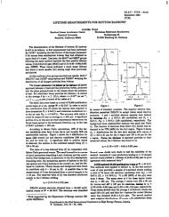
We have recently tested a batch of twelve prototype silicon detectors (four<br />
of each size) fabricated on &inch wafers [6]. The leakage current per strip Ilecrk<br />
was measured at a bias voltage about 10 V above the depletion voltage and at a<br />
temperature of 25OC.<br />
We consider a strip to be acceptable provided that &k 5 200 nA; above<br />
this value of leakage current, the shot noise contribution begins to become non-<br />
negligible, and the dynamic range of our electronics is exceeded. We find that<br />
99.9% of the strips are acceptable. Moreover, 99% of the strips have &,,k 5 10<br />
nA. Hence our testing so far indicates that satisfactory detectors up to 9 cm in<br />
active length can be made.<br />
We have also investigated the effects of radiation on detector leakage current.<br />
A single layer-3 detector was irradiated up to 220 krad in a s°Co radiation well.<br />
There was no detector bias voltage applied during the irradiation. We found<br />
that the strip leakage current increased linearly at the rate of = 90 nA per Mrad.<br />
Taking account of the strip volume (this is useful if the damage is a bulk effect) we<br />
can express the leakage current increase as k: 10m4 A per cm3 per Mrad. These<br />
results imply that radiation exposures up to two Mrad should give acceptable<br />
strip leakage currents.<br />
4.2.2 The Micropkz Integrated Circuit<br />
-<br />
The Microplex read-out chip contains 128 channels of charge-sensitive amplie<br />
fiers with multiplexed analog output. The design has evolved from the original<br />
one (version 1 -described in ref. [4]) t o include double-correlated sampling (ver-<br />
sion 2-see ref. [7]), as well as options for sparse-field read-out and rapid turn-on<br />
6
i ,;’ of the amplifiers (version 3). The fabrication technology is NMOS using 5 pm<br />
. design rules.<br />
- -<br />
_??_<br />
We have investigated the radiation hardness of chip versions 1 and 2. The<br />
results are presented in reference [8]. Briefly: with all power off, three out of four<br />
chips survived more than one Mrad exposure in a ‘%o radiation well, but the<br />
fourth chip died after 74 krad; with power on the analog section of the circuit<br />
(but not the digital section), chip failure occurred after exposures in the range of<br />
2.5 to 32 krad on a sample of 8 chips. The radiation hardness properties of chip<br />
version 3 are now under investigation. As version 3 was fabricated at a different<br />
silicon foundry than versions 1 and 2, its resistance to radiation due to processing<br />
may be different.<br />
4.3 Mechanical Support and Alignment<br />
In order to capitalize on the intrinsic detector module spatial resolution of<br />
55 pm, it is necessary to have.a mechanical support structure, in conjunction<br />
with an alignment strategy, that will provide known and stable positions of each<br />
module to much better than 5 pm. We do not intend that the mechanical sup-<br />
port structure should set the placement of the modules to very high precision;<br />
this would be very difficult and costly to achieve. Instead, the support structure<br />
should provide moderate placement accuracy (-12 pm) with high placement sta-<br />
bility (~2 pm). The actual positions of the modules are then measured to high _<br />
precision (-2 pm) with the alignment procedure described in section 4.3.2.<br />
1.3.1 The Mechanical Support Structure<br />
Fig. 3 shows a photograph of the mechanical support structure. The SSVD<br />
will be made from two hemi-cylmdrical structures; these will be independently<br />
mounted on the beampipe with a three-point suspension. Each hemi-cylinder<br />
will be composed of slotted aluminum end-pieces (fabricated with electrodis-<br />
charge machining), plus inner and outer beryllium shells (each approximately<br />
7<br />
--<br />
_
i ,c-’ 0;11% r.1. thick). A detector module will be inserted into opposing slots in the<br />
. two endpieces. Two compressed-spring fixtures, ‘one glued onto each end of the<br />
module, will locate and hold the module in the slots. With this system, we expect<br />
to obtain relative positions of the modules which will be accurate in the azimuthal<br />
direction to better than 12 pm, and which will have a long-term stability better<br />
t&m 2 pm.<br />
1.3.2 Alignment<br />
The basic elements to be aligned are the 36 detector modules, not the 18,000<br />
individual strips. The inter-alignment of the 512 strips on an individual silicon<br />
detector is provided by the photolithographic process, as developed for integrated<br />
circuit fabrication, and is accurate to better than 1 pm over the detector area.<br />
This brings an enormous simplification to the alignment procedure.<br />
The initial step in the alignment strategy concerns the relative alignment<br />
of the 18 modules that make up one of the two hemi-cylindrical sections of the<br />
SSVD. This will be achieved by (a) optical position measurement of the modules<br />
during the assembly; (b) relative position measurements for the completed system<br />
using a high energy charged particle beam or a collimated x-ray beam; and (c)<br />
checks on the alignment, after installation in the Mark <strong>II</strong> detector, with tracks<br />
from Z” decays.<br />
-The next step is the alignment of the SSVD hemi-cylinders relative to the<br />
vertex and central drift chambers (VDC and CDC). This will be done with high<br />
momentum tracks from 2” decays and cosmic rays. In order to compensate<br />
_T_ for possible movement of the SSVD with respect to the VDC and CDC during -<br />
--the<br />
time necessary to accumulate.enough tracks to give the desired accuracy, the<br />
- i* relative position of the SSVD and VDC will be monitored with capacitive probes.<br />
These probes will be mounted on the outside of the SSVD and will match with<br />
ground pads placed on the inner wall of the VDC.<br />
8
i ;” - The final step is the measurement of the position of the interaction point<br />
.<br />
(IP). This can only be done with Z” decays, using tracks that originate from the<br />
primary vertex. The events Z” + e+e- or p+p- are particularly suitable for this<br />
purpose. The electron and muon tracks are (a) guaranteed to come from the IP<br />
and (b) have very high momentum (46 GeV/c) which reduces the error on track<br />
extrapolation due to multiple scattering to a negligible amount.<br />
One further point needs to be mentioned concerning the IP position mea-<br />
surement. Although the IP is only 2 pm in radius, the stability of its position is<br />
unknown. The SLC feedback system that keeps the electron and positron beams<br />
in collision, only insures that the two beams have a small relative displacement;<br />
there is nothing to prevent the beams from moving together. Therefore, changes<br />
in the IP position may need to be measured with beam position monitors placed<br />
near the IP [9].<br />
- 4.4 Impact Parameter Resolution<br />
.=<br />
The expected impact parameter resolution ob for the SSVD (using the hits<br />
from the VDC and CDC as well), as a function of track momentum p, is shown in<br />
fig. 4. This is for particles at a production angle of 90’. The calculation is based<br />
on the SSVD geometry and material, and assumes an intrinsic spatial resolution<br />
of 5 pm. It also takes account of the 0.36% r.1. thickness for the beam pipe.<br />
The curve shown in fig. 4 is specified by:<br />
with p expressed in units of GeV/c and ob given in pm. -The “5” comes from<br />
- the intrinsic resolution and the %7/p” is due to multiple scattering. This result<br />
‘satisfies the design goal for ob as given in point 2a.<br />
5. Status and Summary<br />
-
i ,c-’ - Fizqd Target Style Detectors: a telescope of three detectors has been tested in<br />
. a beam and gave clean separation between signal and noise, a spatial resolution<br />
better than 5 pm, and a two-track separation better than 150 pm. One of these<br />
silicon detectors was placed at the center of the Mark <strong>II</strong> detector and successfully<br />
took data on cosmic ray events.<br />
The Silicon Detector Module: all the separate parts for a number of proto-<br />
types are in hand and working, including silicon detectors fabricated from 4-inch<br />
diameter wafers. A prototype module is being assembled and will soon be tested<br />
both electrically, and with 60 keV x-rays from an 241Am source (60 keV corre-<br />
sponds to 77% of the signal from a minimum ionizing particle at normal inci-<br />
dence). The effects of radiation damage on the custom-designed read-out chips<br />
are being studied.<br />
Mechanical Support and Alignment: a prototype set of slotted aluminum<br />
end-pieces has been made with electrodischarge machining. Compressed-spring<br />
fixtures for holding the silicon detector modules in the slots are being tested. A<br />
prototype capacitive probe system for monitoring the changes in relative position<br />
of the SSVD and the vertex drift chamber is being assembled.<br />
The Silicon Strip Vertez Detector: there are many challenges ahead but we<br />
expect to have the final SSVD ready for installation in the Mark <strong>II</strong> detector at<br />
the SLC by the spring of 1988.<br />
Acknowledgements<br />
We warmly acknowledge the engineering and design help of Walter Nilsson<br />
(U.C. Santa Cruz), Leonardus Hubbeling (CERN), Michael Studzinski and An-<br />
_e_ negret Wagner (SLAC).<br />
- .- L.<br />
10<br />
;<br />
-
i ,c- Rizferepcp<br />
[l] Proposal for the Addition of a Silicon p-strip Detector to the Mark <strong>II</strong> Detec-<br />
tor at the SLC, by the Mark <strong>II</strong> Collaboration, SLAC Proposal (September,<br />
1985) unpublished.<br />
[2] K. Hayes, Nucl. Instr. and Methods, this issue.<br />
[3] T. Himel, p rivate communication<br />
[4] J.T. Walker et al., Nucl. Instrum. & Methods 226, (1984) 200.<br />
IS] C. Adolphsen et al., Nucl. Instrum. & Methods A253, (1987) 444.<br />
(61 These prototype detectors were fabricated by Hamamatsu Photonics K.K.,<br />
Hamamatsu City, Japan.<br />
[7] G. Anzivino et al., Nucl. Instrum. & Methods A243, (1986) 153.<br />
- (81 A. Breakstone et al., IEEE Trans. Nucl. Sci. NS-34(1987) 491.<br />
[9] D. Burke et al., Proceedings of the Second Mark <strong>II</strong> Workshop on SLC<br />
Physics, SLAC-Report-306 (1986) 420.<br />
11
i ,c- Figure Captions<br />
_z.<br />
-.-<br />
1. The layout of the Silicon Strip Vertex Detector.<br />
2. The plan for a silicon detector module.<br />
3. A photograph of the prototype mechanical support structure. Shown from<br />
left to right are a simplified dummy detector module, two slotted end pieces<br />
joined by an inner shell, and an outer shell.<br />
4. The impact parameter resolution ob as a function of the track momentum.<br />
The tracks are produced at 90’ and are measured in the SSVD as well as<br />
in the central and vertex drift chambers.<br />
12
i ,c-<br />
.<br />
Table 1<br />
Proper&s*-of Prototype Cinch Silicon Detectors<br />
Detector Property layer 1 layer 2 layer 3 units<br />
layer radius<br />
strip pitch<br />
number of strips<br />
active length<br />
total length<br />
active width<br />
total width<br />
thickness<br />
strip width<br />
depletion voltage<br />
capacitance*<br />
(to other strips)<br />
capacitance*<br />
(to backplane)<br />
* calculated.<br />
30 34 38<br />
25 29 33<br />
512 512 512<br />
72 82 90<br />
75 85 94<br />
13 15 17<br />
14 16 18<br />
300 300 300<br />
8 8 8<br />
- 50 - 50 - 50<br />
8.2 8.8 9.3<br />
0.6 0.8 1.0<br />
13<br />
Pm<br />
mm<br />
mm<br />
mm<br />
mm<br />
Pm<br />
pm<br />
V<br />
PP<br />
PP
3-07 1 cm<br />
Vertex Drift Chamber<br />
( Inner Wall 1<br />
Beam Pipe<br />
Fig. 1<br />
5710Al
Fig. 2<br />
3-07<br />
5710~2
Fig. 3
_=.<br />
-<br />
80<br />
60<br />
b” 40<br />
4-87<br />
20<br />
0<br />
0 2 4 6 8 IO<br />
Momentum (GeVk) 5710A3<br />
Fig. 4