Vibration Analysis of Tread Brake Block in the ... - university press
Vibration Analysis of Tread Brake Block in the ... - university press
Vibration Analysis of Tread Brake Block in the ... - university press

You also want an ePaper? Increase the reach of your titles
YUMPU automatically turns print PDFs into web optimized ePapers that Google loves.
Abstract— This paper deals with <strong>the</strong> frequency analysis <strong>of</strong> <strong>the</strong><br />
abnormal vibration <strong>in</strong> <strong>the</strong> specific speed range when <strong>the</strong> tread brake<br />
test is applied <strong>in</strong> <strong>the</strong> brake dynamometer. Generally brake system <strong>of</strong><br />
railway vehicles has a crucial role for <strong>the</strong> safety as well as rid<strong>in</strong>g<br />
quality <strong>of</strong> passengers. And dynamometer tests are widely used to<br />
evaluate <strong>the</strong> friction and wear performance <strong>of</strong> railroad friction<br />
composition brake shoes <strong>in</strong>clud<strong>in</strong>g <strong>the</strong> emergence brake, cont<strong>in</strong>uous<br />
brake, and so on. Experiments on <strong>the</strong> brake dynamometer for <strong>the</strong> high<br />
speed tra<strong>in</strong> are provided to illustrate <strong>the</strong> frequency analysis <strong>of</strong> <strong>the</strong><br />
abnormal vibration <strong>in</strong> vehicle speed at 140 [km/h] and 70 [km/h]<br />
under <strong>the</strong> 920 [mm] wheel diameter us<strong>in</strong>g <strong>the</strong> 3-axis accelerometers.<br />
Keywords— <strong>Tread</strong> <strong>Brake</strong>, <strong>Brake</strong> Dynamometer, Railway Vehicle,<br />
3-Axis Accelerometers.<br />
G<br />
INTERNATIONAL JOURNAL OF SYSTEMS APPLICATIONS, ENGINEERING & DEVELOPMENT<br />
Issue 1, Volume 5, 2011<br />
<strong>Vibration</strong> <strong>Analysis</strong> <strong>of</strong> <strong>Tread</strong> <strong>Brake</strong> <strong>Block</strong> <strong>in</strong> <strong>the</strong><br />
<strong>Brake</strong> Dynamometer for <strong>the</strong> High Speed Tra<strong>in</strong><br />
I. INTRODUCTION<br />
ENERALLY brake system <strong>of</strong> railway vehicles has a crucial<br />
role for <strong>the</strong> safety as well as rid<strong>in</strong>g quality <strong>of</strong><br />
passengers[1]-[3]. Dur<strong>in</strong>g <strong>the</strong> early 19th century various<br />
attempts were made to get away from <strong>the</strong> concept <strong>of</strong> vehicle<br />
brakes which had to be <strong>in</strong>dividually controlled and provide a<br />
tra<strong>in</strong> brake with one po<strong>in</strong>t <strong>of</strong> control. A scheme <strong>of</strong> 1840 had a<br />
cha<strong>in</strong> which ran along <strong>the</strong> tra<strong>in</strong> to <strong>the</strong> guard's position at <strong>the</strong> rear<br />
where it was wound round a drum. To apply <strong>the</strong> brake <strong>the</strong> drum<br />
was lowered until it touched an axle, caus<strong>in</strong>g it to rotate and<br />
tighten <strong>the</strong> cha<strong>in</strong>. Levers connected to <strong>the</strong> cha<strong>in</strong> applied <strong>the</strong><br />
brakes In addition, as railways developed dur<strong>in</strong>g <strong>the</strong> mid 18th<br />
century, <strong>the</strong>re were a number <strong>of</strong> accidents caused by tra<strong>in</strong>s<br />
becom<strong>in</strong>g uncoupled (a breakaway) or just fail<strong>in</strong>g to stop.<br />
Sometimes, breakaways ran down a grade and collided with <strong>the</strong><br />
follow<strong>in</strong>g tra<strong>in</strong> or tra<strong>in</strong>s became parted and <strong>the</strong> second half ran<br />
<strong>in</strong>to <strong>the</strong> front half after <strong>the</strong> crew had stopped it because <strong>the</strong>y had<br />
noticed <strong>the</strong> uncoupl<strong>in</strong>g. The traditional form <strong>of</strong> wheel tread<br />
brake consist<strong>in</strong>g <strong>of</strong> a block <strong>of</strong> friction material which could be<br />
cast iron, wood or a composition material hung from a lever and<br />
be<strong>in</strong>g <strong>press</strong>ed aga<strong>in</strong>st <strong>the</strong> wheel tread by air <strong>press</strong>ure <strong>in</strong> <strong>the</strong> air<br />
brake or atmospheric <strong>press</strong>ure <strong>in</strong> <strong>the</strong> case <strong>of</strong> <strong>the</strong> vacuum brake.<br />
Dynamometers are a device for measur<strong>in</strong>g <strong>the</strong> torque, force,<br />
or power available from a rotat<strong>in</strong>g shaft. The shaft speed is<br />
measured with a tachometer, while <strong>the</strong> turn<strong>in</strong>g force or torque <strong>of</strong><br />
<strong>the</strong> shaft is measured with a scale or by ano<strong>the</strong>r method. The<br />
first dynamometer was designed to measure <strong>the</strong> brake<br />
horsepower <strong>of</strong> a motor. This <strong>in</strong>vention was <strong>the</strong> work <strong>of</strong> an<br />
M<strong>in</strong>-Soo Kim<br />
1<br />
eng<strong>in</strong>eer, Gaspard. He <strong>in</strong>vented <strong>the</strong> Prony <strong>Brake</strong> Dynamometer<br />
<strong>in</strong> 1821 <strong>in</strong> Paris. Variations <strong>of</strong> this dynamometer are still <strong>in</strong> use<br />
today.<br />
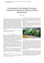
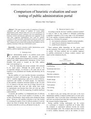
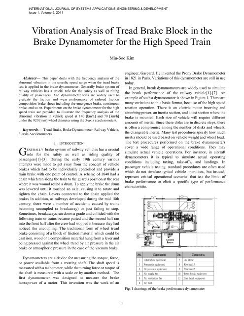
In general, break dynamometers are widely used to simulate<br />
<strong>the</strong> break performance <strong>of</strong> <strong>the</strong> railway vehicle[4]-[7]. An<br />
example <strong>of</strong> such a dynamometer is shown <strong>in</strong> Figure 1. There are<br />
many variations to this basic format, because <strong>of</strong> <strong>the</strong> high speed<br />
rotation operation. There is an electric motor <strong>in</strong>sert<strong>in</strong>g and<br />
absorb<strong>in</strong>g power, an <strong>in</strong>ertia section, and a test section where <strong>the</strong><br />
brake is mounted. Each size <strong>of</strong> vehicle will require different<br />
amounts <strong>of</strong> <strong>in</strong>ertia. S<strong>in</strong>ce <strong>the</strong>se disks are <strong>in</strong> discrete steps, <strong>the</strong>re<br />
is <strong>of</strong>ten a compromise among <strong>the</strong> number <strong>of</strong> disks and wheels,<br />
<strong>the</strong> changeable <strong>in</strong>ertia. Many test procedures specify how much<br />
<strong>in</strong>ertia should be used based on vehicle weight and wheel load.<br />
The test procedures performed on <strong>the</strong> brake dynamometers<br />
cover a wide range <strong>of</strong> operational conditions. They may<br />
simulate actual vehicle operations. For <strong>in</strong>stance, <strong>in</strong> aircraft<br />
dynamometers it is typical to simulate actual operat<strong>in</strong>g<br />
conditions <strong>in</strong>clud<strong>in</strong>g tax<strong>in</strong>g, take-<strong>of</strong>fs, and land<strong>in</strong>gs. In<br />
passenger vehicle test<strong>in</strong>g, standard procedures are <strong>of</strong>ten used<br />
which do not simulate typical vehicle operations, but <strong>in</strong>stead,<br />
represent critical operational scenarios that test <strong>the</strong> limits <strong>of</strong><br />
brake performance or elicit a specific type <strong>of</strong> performance<br />
characteristic.<br />
Fig. 1 draw<strong>in</strong>gs <strong>of</strong> <strong>the</strong> brake performance dynamometer
INTERNATIONAL JOURNAL OF SYSTEMS APPLICATIONS, ENGINEERING & DEVELOPMENT<br />
Issue 1, Volume 5, 2011<br />
This paper conta<strong>in</strong>s <strong>the</strong> frequency analysis <strong>of</strong> <strong>the</strong> abnormal<br />
vibration <strong>in</strong> vehicle speed at 140 [km/h] and 70 [km/h]<br />
consider<strong>in</strong>g <strong>the</strong> 920 [mm] wheel diameter based on <strong>the</strong> 3-axis<br />
accelerometers.<br />
This paper is organized as follows. Section 2 overviews a<br />
brake dynamometer. Section 3 describes <strong>the</strong> experiment<br />
environment for <strong>the</strong> tread brake for analyz<strong>in</strong>g <strong>the</strong> abnormal<br />
vibration when <strong>the</strong> tread brake is applied. Section 4 shows <strong>the</strong><br />
experiment results. The ma<strong>in</strong> conclusions are <strong>the</strong>n summarized<br />
<strong>in</strong> section 5.<br />
II. BRAKE DYNAMOMETER<br />
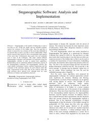
A dynamometer consists <strong>of</strong> <strong>the</strong> follow<strong>in</strong>g ma<strong>in</strong> elements.<br />
The drive-tra<strong>in</strong> consists <strong>of</strong> <strong>the</strong> follow<strong>in</strong>g elements: motor,<br />
<strong>in</strong>terchangeable flywheels and brake disk. The flywheels and<br />
brake disk is matched to <strong>the</strong> part number to be tested.<br />
The test bed consist <strong>of</strong> <strong>the</strong> follow<strong>in</strong>g elements: caliper &<br />
adapter, power transfer axle, load bear<strong>in</strong>g arm and load cell to<br />
calculate <strong>the</strong> break<strong>in</strong>g force.<br />
Fig. 2 brake performance dynamometer for high speed tra<strong>in</strong><br />
<strong>Brake</strong> dynamometer is designed to simulate <strong>the</strong> brake<br />
characteristic <strong>of</strong> <strong>the</strong> high speed tra<strong>in</strong>, and has a function <strong>of</strong><br />
record <strong>the</strong> data which can be reproduced and help to analyze and<br />
compare <strong>the</strong> experimental object, and also is used to develop<br />
and test <strong>the</strong> brake system.<br />
The expected effect and practical scheme <strong>of</strong> <strong>the</strong> brake<br />
dynamometer are follow<strong>in</strong>gs:<br />
(1) Development <strong>of</strong> <strong>the</strong> brake, disk-pad, wheel and brake<br />
system <strong>of</strong> <strong>the</strong> high-speed & conventional tra<strong>in</strong><br />
(2) Test and performance evaluation <strong>of</strong> <strong>the</strong> brake system <strong>of</strong><br />
<strong>the</strong> high-speed & conventional tra<strong>in</strong> with <strong>the</strong> <strong>in</strong>ternational<br />
standard<br />
(3) Performance and certification test <strong>of</strong> <strong>the</strong> brake system <strong>of</strong><br />
<strong>the</strong> manufactured high speed tra<strong>in</strong>.<br />
Briefly, <strong>the</strong> dynamometer has <strong>the</strong> follow<strong>in</strong>g features that<br />
make it suitable for brake show test<strong>in</strong>g:<br />
(1) a 397 [kW] (540 [HP]) DC motor capable <strong>of</strong> speeds from<br />
0 to 2,500[ rpm] <strong>in</strong> ei<strong>the</strong>r direction with dynamic control.<br />
2<br />
(2) flywheel disks that allow selection <strong>of</strong> <strong>in</strong>ertias <strong>in</strong> 100 equal<br />
<strong>in</strong>crements rang<strong>in</strong>g from 400 to 1,600[kg·㎡] with 820[mm]<br />
wheel except 1700[kg·㎡].<br />
(3) brake cyl<strong>in</strong>ders capable <strong>of</strong> ei<strong>the</strong>r 60 or 120 [kN] forces<br />
with controlled force.<br />
(4) precise measurement <strong>of</strong> speed, torque, temperature, and<br />
stop distance.<br />
(5) computer control <strong>of</strong> test sequence, test parameters, and<br />
data acquisition.<br />
Table 1 shows <strong>the</strong> ma<strong>in</strong> features <strong>of</strong> <strong>the</strong> brake dynamometer<br />
that make it suitable for brake shoe test<strong>in</strong>g<br />
Table 1 Ma<strong>in</strong> specification <strong>of</strong> <strong>the</strong> brake dynamometer<br />
Max. drive power 397kW(540HP)<br />
Max. drive torque 2,527Nm<br />
Max. drive speed 2,500rpm(400km/h )<br />
Max. brake torque 25,000Nm<br />
Pressure <strong>Brake</strong> 6,000 N x 2<br />
Flywheel Inertia<br />
Max./M<strong>in</strong>.<br />
1900kg·㎡/400kg·㎡<br />
Diameter <strong>of</strong> <strong>the</strong> test wheel Φ700∼1120mm<br />
Acceleration time<br />
(0~1500rpm)<br />
2 m<strong>in</strong>. 30 sec<br />
III. EXPERIMENTAL ENVIRONMENT<br />
The friction coefficients between dry and wet condition must<br />
not deviate from each o<strong>the</strong>r by more than 15% under <strong>the</strong> same<br />
conditions accord<strong>in</strong>g to <strong>the</strong> requirements <strong>of</strong> <strong>the</strong> UIC CODE<br />
541-4 [10].<br />
The <strong>in</strong>stantaneous friction coefficient µ a , which is<br />
determ<strong>in</strong>ed <strong>in</strong> any moment <strong>of</strong> brak<strong>in</strong>g by <strong>the</strong> ratio <strong>of</strong> total<br />
brak<strong>in</strong>g force F t to total contact force F b , is calculated as<br />
F<br />
t<br />
µ a =<br />
(1)<br />
Fb<br />
And <strong>the</strong> mean friction coefficient µ m determ<strong>in</strong>ed from<br />
reach<strong>in</strong>g 95% <strong>of</strong> <strong>the</strong> nom<strong>in</strong>al contact force Fb <strong>of</strong> <strong>the</strong> friction<br />
coefficient µ m for <strong>the</strong> brak<strong>in</strong>g distance S 2 as (2).<br />
2 1<br />
= ∫<br />
S<br />
µ m µ ads<br />
(2)<br />
S<br />
2<br />
It was found from <strong>the</strong> results <strong>of</strong> <strong>the</strong> tread brake test appeared<br />
0
INTERNATIONAL JOURNAL OF SYSTEMS APPLICATIONS, ENGINEERING & DEVELOPMENT<br />
Issue 1, Volume 5, 2011<br />
from someth<strong>in</strong>g abnormal vibration <strong>in</strong> <strong>the</strong> rang<strong>in</strong>g <strong>of</strong> <strong>the</strong> vehicle<br />
speed at 140 [km/h] (i.e. about 808 [rpm]) and 70 [km/h] (i.e.<br />
about 404 [rpm]) consider<strong>in</strong>g <strong>the</strong> 920 [mm] wheel diameter.<br />
Therefore, we exam<strong>in</strong>ed <strong>the</strong> frequency analysis on <strong>the</strong> axle and<br />
<strong>the</strong> brake block us<strong>in</strong>g <strong>the</strong> 3-axis accelerometers and<br />
displacement measure sensor.<br />
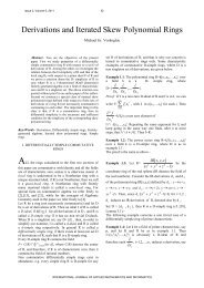
Fig. 3 shows <strong>the</strong> surface <strong>of</strong> <strong>the</strong> wheel tread when it applied <strong>the</strong><br />
brak<strong>in</strong>g process at <strong>in</strong>itial speed <strong>of</strong> 270 [km/h]. We can observe<br />
<strong>the</strong> movement <strong>of</strong> <strong>the</strong> <strong>the</strong>rmal band accord<strong>in</strong>g to <strong>the</strong> speed<br />
variation.<br />
Fig.3 <strong>Tread</strong> break<strong>in</strong>g test at 180 [km/h]<br />
Fig. 4 shows <strong>the</strong> abnormal vibration phenomenon <strong>of</strong> <strong>the</strong> tread<br />
brak<strong>in</strong>g torque (or brak<strong>in</strong>g force F t ) <strong>in</strong> <strong>the</strong> range <strong>of</strong> <strong>the</strong> vehicle<br />
speed at 140 [km/h] .<br />
Fig. 4 torque and <strong>press</strong>ure brake <strong>of</strong> tread brake<br />
Fig. 5 position and coord<strong>in</strong>ate system <strong>of</strong> <strong>the</strong> 3-axis accelerometers<br />
3<br />
The position and coord<strong>in</strong>ate system <strong>of</strong> two accelerometers for<br />
measur<strong>in</strong>g <strong>the</strong> vibration characteristic and a laser sensor for<br />
measur<strong>in</strong>g <strong>the</strong> displacement appear <strong>in</strong> Fig. 5 and Fig. 6,<br />
respectively.<br />
Fig. 6 position and coord<strong>in</strong>ate system <strong>of</strong> <strong>the</strong> laser sensor for<br />
measur<strong>in</strong>g <strong>the</strong> x-axis displacement<br />
In <strong>the</strong> tread brak<strong>in</strong>g test <strong>of</strong> <strong>the</strong> brake dynamometer, <strong>the</strong> <strong>in</strong>itial<br />
test speed is set out at 270 [km/h] with composite tread brake<br />
blocks for <strong>the</strong> high speed tra<strong>in</strong>.<br />
Fig. 7 measurement system for <strong>the</strong> brake experiment (DAQ)<br />
Table 2 summarizes <strong>the</strong> ma<strong>in</strong> features <strong>of</strong> <strong>the</strong> DAQ systems<br />
for measur<strong>in</strong>g <strong>the</strong> signals and those <strong>of</strong> <strong>the</strong> various sensors for<br />
analyz<strong>in</strong>g <strong>the</strong> vibration <strong>of</strong> <strong>the</strong> axle [11].<br />
Table 2 Ma<strong>in</strong> specification <strong>of</strong> <strong>the</strong> DAQ and sensors<br />
DAQ<br />
DEWE-43<br />
8 analog <strong>in</strong>puts (24 bits, 50ks/s)<br />
8 analog <strong>in</strong>puts (24 bits, 50ks/s)<br />
8 counter <strong>in</strong>puts<br />
2 CAN-bus <strong>in</strong>terface
INTERNATIONAL JOURNAL OF SYSTEMS APPLICATIONS, ENGINEERING & DEVELOPMENT<br />
Issue 1, Volume 5, 2011<br />
Triaxial<br />
Accelerometer<br />
Laser sensor<br />
KISTLER K-Beam 8393B10<br />
measures 3-axis simultaneously<br />
frequency response: 0~250Hz<br />
acceleration range:±10g<br />
Omron ZX-LD100L<br />
100mm±40mm with 16µm resolution<br />
In <strong>the</strong> process <strong>of</strong> <strong>the</strong> brake stop application, <strong>the</strong> motor<br />
<strong>in</strong>creases speed to <strong>the</strong> <strong>in</strong>itial sett<strong>in</strong>g value and <strong>the</strong>n put on <strong>the</strong><br />
brakes. The <strong>in</strong>itial speed for <strong>the</strong> test is set up 270 [km/h]. Fig. 8<br />
shows <strong>the</strong> measurement data on <strong>the</strong> dynamometer control desk<br />
<strong>in</strong>clud<strong>in</strong>g <strong>the</strong> vehicle speed, <strong>in</strong>stantaneous friction coefficient,<br />
brake force, wheel temperature, and contact force.<br />
(a) transition <strong>of</strong> <strong>the</strong> vehicle speed from 270 [km/h] to 0 [km/h]<br />
(b) <strong>in</strong>stantaneous friction coefficient, brake force, wheel temperature,<br />
and contact force<br />
Fig. 8 measurement data on <strong>the</strong> dynamometer control desk<br />
In <strong>the</strong> tread brak<strong>in</strong>g test, brak<strong>in</strong>g distance was measured<br />
2,228 [m] and brak<strong>in</strong>g time was gauged 65.3 [sec] dur<strong>in</strong>g <strong>the</strong><br />
brak<strong>in</strong>g test with cyl<strong>in</strong>der <strong>press</strong>ure 22.6[kg/cm2] (i.e. cyl<strong>in</strong>der<br />
force 5.9 [kN]).<br />
An <strong>in</strong>ertia dynamometer system provides a fixed <strong>in</strong>ertial mass<br />
flywheel and computes <strong>the</strong> power required to accelerate <strong>the</strong><br />
flywheel (load) from <strong>the</strong> start<strong>in</strong>g to <strong>the</strong> end<strong>in</strong>g <strong>the</strong> brak<strong>in</strong>g<br />
application. The <strong>in</strong>ertia value was chosen 800 [kg•㎡] because<br />
<strong>the</strong> UIC test program prescribed 4 [ton] (mass per brake disc) <strong>in</strong><br />
case <strong>of</strong> <strong>the</strong> high speed tra<strong>in</strong>[10]. The brake application force<br />
sett<strong>in</strong>g up 5.9 [kN] is supplied by <strong>the</strong> com<strong>press</strong>ed air cyl<strong>in</strong>ders<br />
act<strong>in</strong>g on <strong>the</strong> brake shoe. Dur<strong>in</strong>g brak<strong>in</strong>g, <strong>the</strong> force should not<br />
4<br />
vary from <strong>the</strong> normal value.<br />
(a) on <strong>the</strong> axle<br />
(b) on <strong>the</strong> brake block<br />
Fig. 9 output signals <strong>of</strong> <strong>the</strong> tri-axial accelerometer<br />
Fig. 9 describes <strong>the</strong> output signals <strong>of</strong> <strong>the</strong> tri-axial accelerometer<br />
<strong>in</strong>stalled on <strong>the</strong> axle and brake block for analyz<strong>in</strong>g <strong>the</strong> vibration.<br />
IV. EXPERIMENTS<br />
A. <strong>Vibration</strong> <strong>of</strong> <strong>the</strong> Axle and <strong>Brake</strong> <strong>Block</strong><br />
The measur<strong>in</strong>g signals for analyz<strong>in</strong>g <strong>the</strong> vibration <strong>of</strong> <strong>the</strong> axle<br />
and brake block us<strong>in</strong>g <strong>the</strong> 3-axis accelerometers are transmitted<br />
to <strong>the</strong> DAQ via A/D converter, and <strong>the</strong> frequency analysis is<br />
performed.<br />
Fig. 10 DAQ screen for <strong>the</strong> analyz<strong>in</strong>g <strong>the</strong> vibration
INTERNATIONAL JOURNAL OF SYSTEMS APPLICATIONS, ENGINEERING & DEVELOPMENT<br />
Issue 1, Volume 5, 2011<br />
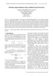
Fig. 10 shows <strong>the</strong> experimental results about <strong>the</strong> full<br />
measurement data <strong>in</strong>clud<strong>in</strong>g <strong>the</strong> brak<strong>in</strong>g images <strong>in</strong>stalled with<br />
<strong>the</strong> 3-axis accelerometers on <strong>the</strong> axle and its frequency analysis<br />
at 140 [km/h].<br />
We can represent <strong>the</strong> results <strong>of</strong> <strong>the</strong> frequency analysis at<br />
132[km/h] <strong>in</strong> <strong>the</strong> axle vibration and brake block vibration as<br />
follows:<br />
Common ma<strong>in</strong> frequencies <strong>of</strong> <strong>the</strong> x-axis : 75.68 and<br />
126.95[Hz]<br />
Common ma<strong>in</strong> frequencies <strong>of</strong> <strong>the</strong> z-axis : 75.68, 114.75,<br />
and 166.02[Hz]<br />
These five ma<strong>in</strong> frequencies (75.68[Hz], 126.95[Hz] and<br />
75.68[Hz], 114.75[Hz], 166.02[Hz]) have similarities between<br />
<strong>the</strong> 3-axis accelerometer on axle and that on <strong>the</strong> brake block at a<br />
speed <strong>of</strong> 132 km/h.<br />
Fig. 11 illustrates <strong>the</strong> measurement data with <strong>the</strong> 3-axis<br />
accelerometers on <strong>the</strong> brake block and its frequency analysis at<br />
132 [km/h].<br />
(a) on <strong>the</strong> axle<br />
(b) on <strong>the</strong> brake block<br />
Fig. 11 Frequency analysis at 132[km/h]<br />
5<br />
Ma<strong>in</strong> frequencies <strong>of</strong> <strong>the</strong> measurement data <strong>of</strong> <strong>the</strong> 3-axis<br />
accelerometer on <strong>the</strong> axle at 132[km/h] are shown <strong>in</strong> Table 3.<br />
Table 3. Ma<strong>in</strong> frequencies <strong>of</strong> <strong>the</strong> measurement data <strong>of</strong> <strong>the</strong> 3-axis<br />
accelerometer on <strong>the</strong> axle<br />
Axis Frequency [Hz] Voltage [V] No.<br />
75.68 5.16 3<br />
90.332 5.82 4<br />
114.75 5.67 5<br />
x-axis 126.95 11.5 1<br />
168.46 6.03 2<br />
219.73 5.62 6<br />
244.14 4.41 7<br />
90.332 4.87 2<br />
y-axis 129.39 4.83 3<br />
168.46 6.22 1<br />
75.68 1.23 2<br />
z-axis<br />
114.75<br />
166.02<br />
2.85<br />
2.25<br />
1<br />
4<br />
244.14 2.02 3<br />
Table 4. Ma<strong>in</strong> frequencies <strong>of</strong> <strong>the</strong> measurement data <strong>of</strong> <strong>the</strong> 3-axis<br />
accelerometer on <strong>the</strong> brake block<br />
Axis Frequency [Hz] Voltage [V] No.<br />
75.68 10.9 10<br />
126.95 32.2 1<br />
153.82 25.74 2<br />
271.00 15.58 12<br />
322.27 21.28 6<br />
x-axis<br />
412.60<br />
539.55<br />
21.56<br />
15.84<br />
5<br />
11<br />
566.41 22.97 4<br />
605.47 20.55 8<br />
761.72 18.89 9<br />
773.94 20.81 7<br />
790.34 23.52 3<br />
129.39 49.34 2<br />
y-axis 153.81 50.77 1<br />
529.79 26.10 3<br />
75.68 11.7 3<br />
z-axis 114.75 33.2 1<br />
166.02 27.2 2<br />
Next, ano<strong>the</strong>r frequency analysis was performed
INTERNATIONAL JOURNAL OF SYSTEMS APPLICATIONS, ENGINEERING & DEVELOPMENT<br />
Issue 1, Volume 5, 2011<br />
cont<strong>in</strong>uously before and after <strong>the</strong> speed <strong>of</strong> 132 [km/h]. Fig. 12<br />
and Fig 13 shows <strong>the</strong> frequency analysis at vehicle speed 92<br />
[km/h] and 170 [km/h], respectively.<br />
(a) on <strong>the</strong> axle<br />
(b) on <strong>the</strong> brake block<br />
Fig. 12 frequency analysis at 92[km/h]<br />
(a) on <strong>the</strong> axle<br />
6<br />
(b) on <strong>the</strong> brake block<br />
Fig. 13 Frequency analysis at 170[km/h]<br />
Compared with <strong>the</strong> frequency analysis at <strong>the</strong> speed <strong>of</strong><br />
132[km/h], <strong>the</strong> ma<strong>in</strong> frequencies <strong>of</strong> <strong>the</strong> 3-axis accelerometer on<br />
<strong>the</strong> axle have no relevance at all to those on <strong>the</strong> brake block at a<br />
speed <strong>of</strong> 170[km/h] and 92[km/h].<br />
B. Displacement <strong>of</strong> <strong>the</strong> Axle<br />
Displacement data <strong>of</strong> axle were ga<strong>the</strong>red from laser sensor<br />
<strong>in</strong>stalled for measur<strong>in</strong>g <strong>the</strong> movement <strong>of</strong> <strong>the</strong> x-axis and applied<br />
<strong>the</strong> LPF to <strong>the</strong> sensor signals. Fig 14 shows <strong>the</strong> change <strong>of</strong> <strong>the</strong><br />
axle displacement and its frequency analysis at 134 [km/h] are<br />
shown <strong>in</strong> Fig. 15.<br />
Fig. 14 measurement data with <strong>the</strong> axle displacement<br />
The range <strong>of</strong> variation is measured by 0.036[v] under<br />
consider<strong>in</strong>g <strong>the</strong> <strong>in</strong>itial bias and it can be converted <strong>in</strong>to<br />
0.32[mm] displacement with <strong>the</strong> maximum. More accurate<br />
measured values <strong>of</strong> <strong>the</strong> laser sensor <strong>in</strong> ma<strong>in</strong> po<strong>in</strong>ts are<br />
follow<strong>in</strong>gs.<br />
0 ~ 180[km/h]: -0.0065 [v]<br />
200[km/h]: 0.015 [v]<br />
180[km/h]: 0.0294 [v]
INTERNATIONAL JOURNAL OF SYSTEMS APPLICATIONS, ENGINEERING & DEVELOPMENT<br />
Issue 1, Volume 5, 2011<br />
Fig. 15 frequency analysis <strong>of</strong> <strong>the</strong> axle displacement at 134 [km/h]<br />
Ma<strong>in</strong> frequency <strong>of</strong> <strong>the</strong> displacement is marked by 2.441 [Hz]<br />
and 13.22[Hz]. As <strong>the</strong> range <strong>of</strong> <strong>the</strong> fluctuation <strong>of</strong> <strong>the</strong> axle<br />
displacement <strong>in</strong>dicates, <strong>the</strong> abnormal vibration doesn’t result<br />
from <strong>the</strong> clearance <strong>of</strong> <strong>the</strong> ball <strong>in</strong>side <strong>the</strong> bear<strong>in</strong>g.<br />
C. Sound from Microphone<br />
Brak<strong>in</strong>g sound data were measured cont<strong>in</strong>uously before,<br />
dur<strong>in</strong>g and after <strong>the</strong> brake application. And <strong>the</strong>n, <strong>the</strong> frequency<br />
analysis was performed to make a comparison <strong>of</strong> <strong>the</strong> frequency<br />
characteristic between <strong>the</strong> brak<strong>in</strong>g sound and <strong>the</strong> axle vibration.<br />
Fig. 16 shows <strong>the</strong> measurement data with <strong>the</strong> brak<strong>in</strong>g sound<br />
us<strong>in</strong>g <strong>the</strong> microphone. The sound level also grows accord<strong>in</strong>g to<br />
<strong>in</strong>creas<strong>in</strong>g <strong>the</strong> vehicle speed <strong>in</strong> <strong>the</strong> brak<strong>in</strong>g application.<br />
Fig. 16 measurement data with <strong>the</strong> brak<strong>in</strong>g sound<br />
Fig. 17 frequency analysis <strong>of</strong> <strong>the</strong> brak<strong>in</strong>g sound at 134 [km/h]<br />
Ma<strong>in</strong> frequency <strong>of</strong> <strong>the</strong> brak<strong>in</strong>g sound are 168.46 [Hz], 90.332<br />
[Hz], 244.14 [Hz], and 219.73 [Hz]. These two frequencies<br />
(168.46 [Hz], 90.332 [Hz]) have co<strong>in</strong>cidence between <strong>the</strong><br />
brak<strong>in</strong>g noise and measurement data <strong>of</strong> <strong>the</strong> 3-axis<br />
accelerometers on axle at 134 km/h.<br />
7<br />
V. CONCLUSION<br />
<strong>Brake</strong> dynamometer is designed to simulate <strong>the</strong> brake<br />
characteristic <strong>of</strong> <strong>the</strong> high speed tra<strong>in</strong>, and has a function <strong>of</strong><br />
record <strong>the</strong> data which can be reproduced and help to analyze and<br />
compare <strong>the</strong> experimental object, and also is used to develop<br />
and test <strong>the</strong> brake system.<br />
In this paper, we present a tread brake experiments on <strong>the</strong><br />
dynamometer for high speed tra<strong>in</strong> <strong>in</strong> order to analyze <strong>the</strong><br />
abnormal vibration <strong>in</strong> specific vehicle speed at 140 [km/h] and<br />
70 [km/h]. For analysis we use <strong>the</strong> 3-axis accelerometers on <strong>the</strong><br />
axle and on <strong>the</strong> brake block. As a result <strong>of</strong> <strong>the</strong> analysis we could<br />
verify <strong>the</strong> mutual action between axle vibrations and <strong>the</strong> brake<br />
block connection with <strong>the</strong> brake cyl<strong>in</strong>der.<br />
[1]<br />
REFERENCES<br />
Simon Iwnicki, Handbook <strong>of</strong> Railway Vehicle Dynamic, CRC Press,<br />
2006.<br />
[2] Robert L. J., Railway <strong>Brake</strong>s, Autralia: West<strong>in</strong>ghouse <strong>Brake</strong> and S<strong>in</strong>gnal<br />
Co., 1982.Simon Iwnicki, Handbook <strong>of</strong> Railway Vehicle Dynamic, CRC<br />
Press, 2006.<br />
[3] Garg V. K. and Rukkipati R. V., Dynamics <strong>of</strong> Railway Vehicle Systems,<br />
Academic <strong>press</strong>, 1994.<br />
[4] T.E.Johnson, Results <strong>of</strong> Dynamometer Tests <strong>of</strong> <strong>Brake</strong> Shoes Under Full<br />
Load Conditions, Ill<strong>in</strong>ois : Association <strong>of</strong> American Railroads, 1993<br />
[5] Hecht Basch, R., Fash, J., Hasson, R., Dalka, T., McCune, R. and Kafold,<br />
R. “Initial Dynamometer and Laboratory Evaluations <strong>of</strong> Thermally<br />
Sprayed Alum<strong>in</strong>ium <strong>Brake</strong> Discs,” In <strong>Brake</strong>s 2000, International<br />
Conference on Automotive Brak<strong>in</strong>g Technologies for <strong>the</strong> 21st Century,<br />
pp. 163-173, 2000.<br />
[6] QUESTION B-169: Selection <strong>of</strong> parameters for test<strong>in</strong>g <strong>the</strong>rmal limits <strong>of</strong><br />
wheels and brake blocks, Utrecht : ERRI, 1989.<br />
[7] M. C. Fec, H. Sehitoglu, Thermal limits for wheels and brake blocks :<br />
monitoor<strong>in</strong>g <strong>of</strong> solid wheels <strong>in</strong> service (Report No. R-600), Utrecht :<br />
ERRI, 1995<br />
[8] UIC CODE 541-1 <strong>Brake</strong>s – Regulations concern<strong>in</strong>g <strong>the</strong> design <strong>of</strong> brake<br />
components, 6 th<br />
Eds.November 2003.<br />
[9] UIC CODE 541-3 <strong>Brake</strong>s – Disk brakes and <strong>the</strong>ir application – General<br />
th<br />
conditions for <strong>the</strong> approval <strong>of</strong> brake pads, 6 Eds.November 2006.<br />
[10] UIC CODE 541-4 <strong>Brake</strong>s – <strong>Brake</strong>s with composite brake blocks –<br />
rd<br />
General conditions for certification <strong>of</strong> composite brake blocks, 3 Eds.<br />
May 2007.<br />
[11] Dewe-43 Technical Reference Manual, Ver. 1.0.0, DEWESOFT, 2009.<br />
[12] Harper, Graham A., <strong>Brake</strong>s and friction materials : <strong>the</strong> history and<br />
development <strong>of</strong> <strong>the</strong> technologies, London : MEP (Mechanical<br />
Eng<strong>in</strong>eer<strong>in</strong>g Publication, 1998<br />
[13] M<strong>in</strong>-Soo Kim, Joon-Hyuk Park, Byeong-Choon Goo, “Development <strong>of</strong><br />
<strong>Brake</strong> System <strong>of</strong> Railway Vehicles for Real-Time HILS,” The 2007<br />
International Conference on Mechatronics and Information<br />
Technologys(ICMIT 2007), Gifu, Japan, 5-6 December, 2007.<br />
[14] M<strong>in</strong>-Soo Kim, Hyun-Moo Hur, “Brak<strong>in</strong>g/Traction Control Systems <strong>of</strong> a<br />
Scaled Railway Vehicle for <strong>the</strong> Active Steer<strong>in</strong>g Testbed,” The 9th WSEAS<br />
International Conference on ROBOTICS, CONTROL and<br />
MANUFACTURING TECHNOLOGY (ROCOM '09), Hangzhou, Ch<strong>in</strong>a,<br />
May 20-22, 2009.<br />
[15] M<strong>in</strong>-Soo Kim, Hyun-Moo Hur, “Application <strong>of</strong> Brak<strong>in</strong>g/Traction Control<br />
Systems to <strong>the</strong> Scaled Active Steer<strong>in</strong>g Testbed <strong>in</strong> <strong>the</strong> Railway Vehicle,”<br />
WSEAS Transctions on System and Control , 2009.<br />
[16] M<strong>in</strong>-Soo Kim Jeong-Guk Kim, Byeong-Choon Goo, Nam-Po Kim,<br />
“Frequency <strong>Analysis</strong> <strong>of</strong> <strong>the</strong> <strong>Vibration</strong> <strong>of</strong> <strong>Tread</strong> <strong>Brake</strong> Dynamometer for<br />
<strong>the</strong> High Speed Tra<strong>in</strong>,” The 10th WSEAS International Conference on<br />
SIGNAL PROCESSING, COMPUTATIONAL GEOMETRY and<br />
ARTIFICIAL VISION (ISCGAV '10), Taipei, Taiwan, August 20-22,<br />
2010.<br />
[17] Aviles, R., Hennequet, G., Hernandez, A. and Llorente, L. I. “Low<br />
Frequency <strong>Vibration</strong>s <strong>in</strong> Disc <strong>Brake</strong>s at High Car Speed. Part I:
INTERNATIONAL JOURNAL OF SYSTEMS APPLICATIONS, ENGINEERING & DEVELOPMENT<br />
Issue 1, Volume 5, 2011<br />
Experimental Approach,” Int. Journal <strong>of</strong> Vehicle.Dynamics, 1995, 16(6),<br />
542-555.<br />
[18] Lang, A. M. and Smales, H. “An Approach to <strong>the</strong> Solution <strong>of</strong> Disc <strong>Brake</strong><br />
<strong>Vibration</strong> Problems,” In Proceed<strong>in</strong>gs, Brak<strong>in</strong>g <strong>of</strong> Road Vehicles, London,<br />
1983.<br />
M<strong>in</strong>-Soo Kim received <strong>the</strong> B.S., M.S., and Ph.D. degrees <strong>in</strong> electrical<br />
eng<strong>in</strong>eer<strong>in</strong>g from Soongsil University, Seoul, Korea <strong>in</strong> 1995, 1997, and 2003,<br />
respectively. From December 2005 he is a senior researcher at <strong>the</strong> Vehicle<br />
Dynamics & Propulsion Research Department at Korea Railroad Research<br />
Institute, 360-1 Woram-dong, Uiwang-si, Kyonggi-do, 437-757 Korea<br />
(correspond<strong>in</strong>g author to provide phone: +82-31-460-5205; fax:<br />
+82-31-460-5299; e-mail: ms_kim@krri.re.kr). His research <strong>in</strong>terests <strong>in</strong>clude<br />
control systems design <strong>of</strong> railway vehicle and dynamometer test for <strong>the</strong> railway<br />
brake components.<br />
8