Coolant Delivery System for Creep-Feed Grinding - Mechanical ...
Coolant Delivery System for Creep-Feed Grinding - Mechanical ...
Coolant Delivery System for Creep-Feed Grinding - Mechanical ...

Create successful ePaper yourself
Turn your PDF publications into a flip-book with our unique Google optimized e-Paper software.
Dalhousie University MECH 4010 – Design Project I – Fall Term Report<br />
Dalhousie University<br />
<strong>Mechanical</strong> Engineering Department<br />
MECH 4010 – Design Project I<br />
<strong>Coolant</strong> <strong>Delivery</strong> <strong>System</strong> <strong>for</strong> <strong>Creep</strong>-<strong>Feed</strong> <strong>Grinding</strong><br />
Fall Term Report<br />
Team 10<br />
Brian Murphy<br />
David Pottle<br />
Andrew Rockwell<br />
Kyle Ryan<br />
December 4, 2006
Dalhousie University MECH 4010 – Design Project I – Fall Term Report<br />
Table of Contents<br />
List of Tables ......................................................................................................................iii<br />
List of Figures ....................................................................................................................iii<br />
Abstract...............................................................................................................................iv<br />
1.0 Introduction ...................................................................................................................1<br />
1.1 Background In<strong>for</strong>mation...............................................................................................2<br />
1.1.1 <strong>Grinding</strong>..............................................................................................................................2<br />
1.1.2 <strong>Grinding</strong> Wheels.................................................................................................................2<br />
1.1.3 <strong>Grinding</strong> Fluids ...................................................................................................................3<br />
1.1.4 Analysis of the <strong>Grinding</strong> Process .......................................................................................3<br />
1.1.5 Temperatures at the Work Surface ....................................................................................4<br />
1.1.6 <strong>Grinding</strong> Operations and <strong>Grinding</strong> Machines .....................................................................5<br />
1.1.6.1 Surface <strong>Grinding</strong> .........................................................................................................................5<br />
1.1.6.2 <strong>Creep</strong> <strong>Feed</strong> <strong>Grinding</strong> ..................................................................................................................5<br />
1.2 Previous Research of <strong>Coolant</strong> <strong>Delivery</strong> at Dalhousie ..................................................6<br />
2.0 Design Requirements ...................................................................................................8<br />
3.0 Design Options..............................................................................................................9<br />
4.0 Selected Design...........................................................................................................12<br />
4.1 Pump and Motor Options...........................................................................................12<br />
4.1.1 Pump Selection ................................................................................................................12<br />
4.1.2 Drive Selection .................................................................................................................13<br />
4.2 Detailed Final Design Specifications..........................................................................14<br />
5.0 Project Status ..............................................................................................................17<br />
6.0 Cost Analysis...............................................................................................................18<br />
7.0 Conclusions.................................................................................................................19<br />
8.0 References...................................................................................................................21<br />
APPENDIX A – Calculations .............................................................................................22<br />
APPENDIX B – Pump-Motor Curves ................................................................................24<br />
APPENDIX C – Equipment Specifications.......................................................................27<br />
APPENDIX D – Budget ......................................................................................................18<br />
i
Dalhousie University MECH 4010 – Design Project I – Fall Term Report<br />
APPENDIX E – Quotes ......................................................................................................51<br />
APPENDIX F – Winter Term Gantt Chart .........................................................................56<br />
APPENDIX G – Detail Drawings .......................................................................................58<br />
ii
Dalhousie University MECH 4010 – Design Project I – Fall Term Report<br />
List of Tables<br />
Table 1.1 – Hardness values of abrasive materials used in grinding wheels ................3<br />
Table 4.1 – Pump Selection Chart....................................................................................13<br />
List of Figures<br />
Figure 1.1 – Blohm Planomat 408 <strong>Creep</strong>-<strong>Feed</strong> Grinder....................................................1<br />
Figure 1.2 – The geometry of surface grinding.................................................................4<br />
Figure 1.3 – Comparison of (a) conventional surface grinding and (b) creep feed<br />
grinding................................................................................................................................6<br />
Figure 3.1 – <strong>System</strong> Schematic # 1..................................................................................10<br />
Figure 3.2 – <strong>System</strong> Schematic # 2..................................................................................11<br />
Figure 4.1 – Final Design Schematic ...............................................................................16<br />
Figure 4.2 – Final Design Layout .....................................................................................16<br />
iii
Dalhousie University MECH 4010 – Design Project I – Fall Term Report<br />
Abstract<br />
The following report summarizes the basic facts, the proposed design, and the detailed<br />
engineering drawings <strong>for</strong> the upgrade to the coolant delivery system on the Blohm Planomat 408<br />
CNC grinding machine at Dalhousie University. The creep feed grinding machine is the<br />
property of the Dalhousie <strong>Grinding</strong> Research Group. The report will explain how the coolant<br />
delivery system was designed, how it will be installed, and how the upgrades will benefit the<br />
Dalhousie <strong>Grinding</strong> Research Group.<br />
The coolant delivery system will use two pumps and two motors to supply the coolant to the two<br />
desired locations during grinding. The pumps were sized to obtain the pressures and flow rates<br />
required <strong>for</strong> exit velocities to be greater than the tangential velocity of the wheel. The motors <strong>for</strong><br />
the pumps were sized so as to meet the power requirements of this high pressure system. Two<br />
speed controllers are to be installed so that research students are able to experiment with a wide<br />
variety of flow rates.<br />
The report will also outline the amount of progress that has been completed up to this point. The<br />
main progress of the report has been talking to local distributors <strong>for</strong> pumps and motors and<br />
selecting components. The main components of the system have been selected, such as the<br />
pumps, motors, and the variable speed controllers. These components have also been ordered,<br />
<strong>for</strong> an early January installation.<br />
The frame <strong>for</strong> the pumps and motors has been completely designed and a list of materials has<br />
been produced. This list of materials will be used to order the materials so the frame can be<br />
constructed over the Christmas break. With the frame being constructed over the Christmas<br />
break; the pumps, motors, and variable speed controllers will be installed in early January.<br />
iv
Dalhousie University MECH 4010 – Design Project I – Fall Term Report<br />
1.0 Introduction<br />
The Blohm Planomat 408 Computer Numerical Control (CNC) grinding machine in the CNC lab<br />
at Dalhousie University is to be upgraded so that it can used <strong>for</strong> creep-feed profile grinding using<br />
cubic boron nitride (CBN) grinding wheels.<br />
The tangential velocity of a CBN grinding wheel is typically 45 – 60 m/s as compared to the 25 –<br />
35 m/s <strong>for</strong> conventional aluminum oxide grinding wheels. A key component of this upgrade is<br />
the coolant delivery and wheel cleaning system. The current system is not capable of delivering<br />
coolant to the wheel with sufficient profile coverage or velocity. There<strong>for</strong>e, we need to design,<br />
install, and test an upgraded coolant system.<br />
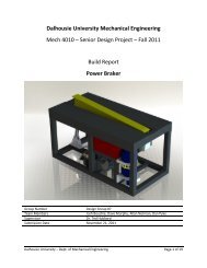
Figure 1.1 – Blohm Planomat 408 <strong>Creep</strong>-<strong>Feed</strong> Grinder<br />
Courtesy: <strong>Mechanical</strong> Engineering Department - Dalhousie University - <strong>Grinding</strong> Research Group
Dalhousie University MECH 4010 – Design Project I – Fall Term Report<br />
1.1 Background In<strong>for</strong>mation<br />
1.1.1 <strong>Grinding</strong><br />
<strong>Grinding</strong> is a material removal process using abrasive particles bonded in the shape of a disk.<br />
These disks are called grinding wheels, which are precisely balanced to rotate at very high<br />
speeds.<br />
<strong>Grinding</strong> can be likened to the milling process, but there are significant differences between the<br />
two. The first key difference in the two processes is the abrasive grains in the grinding wheel are<br />
much smaller and more numerous than the number of teeth on the milling cutter. Also, the<br />
cutting speeds in grinding are much higher. The abrasive particles in grinding wheels are<br />
randomly oriented and possess very large negative rake angles. Finally, a grinding wheel is self<br />
sharpening. As the abrasive particles become dull or break off, new particles are exposed.<br />
Abrasive processes are important in industry and technologically <strong>for</strong> three main reasons.<br />
Abrasive processes can be used on a wide range of materials, ranging from soft metals to<br />
hardened steels, and even on some nonmetallic materials such as ceramics and silicon. Some of<br />
the higher end abrasive processes can be used to produce extremely fine surface finishes, to<br />
0.025 μm (1 μ-in). Finally, certain abrasive processes can hold extremely close tolerances.<br />
[Groover, 2004]<br />
1.1.2 <strong>Grinding</strong> Wheels<br />
There are many different types of grinding wheels that are used in the industry. The first wheel<br />
to be discussed will be the Aluminum Oxide wheel (Al2O3). Al2O3 wheels are the most common<br />
type of grinding wheels. They are mainly used to grind steels, other ferrous metals, and high<br />
strength alloys. Another type of wheel used is Silicon Carbide (SiC). SiC grinding wheels are<br />
slightly harder than Al2O3 wheels, but are not as tough. SiC wheels are generally used to grind<br />
ductile metals such as aluminum, brass, and stainless steels, as well as some brittle materials<br />
such as cast iron and ceramics. Cubic Boron Nitride (cBN) wheels are the second hardest known<br />
to man. These cBN wheels are used <strong>for</strong> grinding much harder materials such as hardened tool<br />
steels, and aerospace alloys. The final type of grinding wheel material most commonly used is<br />
2
Dalhousie University MECH 4010 – Design Project I – Fall Term Report<br />
Diamond. Diamond grinding wheels are produced naturally or synthetically. Diamond grinding<br />
wheels are used on hard, abrasive materials such as ceramics, cemented carbides, and glass.<br />
Table 1.1 – Hardness values of abrasive materials used in grinding wheels<br />
Abrasive Material Knoop Hardness<br />
Aluminum Oxide 2100<br />
Silicon Carbide 2500<br />
Cubic Boron Nitride 5000<br />
Diamond (artificial) 7000<br />
[Groover, 2004]<br />
1.1.3 <strong>Grinding</strong> Fluids<br />
Proper application of cutting fluids reduces thermal effects in the work piece and high work<br />
surface temperatures. Cutting fluids are called grinding fluids when used in the grinding process.<br />
The main purposes of grinding fluids in grinding are reducing friction and removing heat from<br />
the process. Additionally, the grinding fluid is used to wash away pieces of metal chips and<br />
wheel particles.<br />
Types of grinding fluids include grinding oils and emulsified oils. <strong>Grinding</strong> oils are derived<br />
from petroleum and other sources. These products seem to be very attractive due to the large<br />
friction in the grinding process. However, grinding oils pose hazards in terms of fires and<br />
operator health, and their cost is quite high compared to emulsified oils. Additionally, grinding<br />
oils have a low capacity to carry away heat when compared with water based fluids. There<strong>for</strong>e,<br />
mixtures of oils in water are most commonly used as grinding fluids. These types of oil-water<br />
mixtures are usually mixed with higher concentrations than emulsified oils used as conventional<br />
cutting fluids. This way, the friction reduction mechanism is emphasized.<br />
[Groover, 2004]<br />
1.1.4 Analysis of the <strong>Grinding</strong> Process<br />
The cutting in the grinding process is characterized by very high speeds, and very small cut size.<br />
The peripheral speed of the grinding wheel is determined by the rotational speed of the grinding<br />
wheel.<br />
3
Dalhousie University MECH 4010 – Design Project I – Fall Term Report<br />
v = πDN<br />
where v = the surface speed of the wheel (m/s, ft/min, etc.); N = spindle speed (rev/min); D =<br />
wheel diameter (m, ft, etc.).<br />
The depth of the cut, d, is called the infeed. The infeed is the distance the wheel is below the<br />
original work surface. As the grinding process proceeds, the grinding wheel is fed laterally<br />
across the surface of the work piece. The movement of the wheel refers to the crossfeed, and it<br />
determines the width of the grinding path, w. The width of the cut multiplied by the depth of the<br />
cut determines the cross-sectional area of the cut. Most grinding processes, the work piece<br />
moves past the wheel at a certain speed vm. The material removal rate (MRR) of the grinding<br />
process can be determined by<br />
[Groover, 2004]<br />
1.1.5 Temperatures at the Work Surface<br />
MRR = vm<br />
wd<br />
Figure 1.2 – The geometry of surface grinding<br />
Due to the high rake angles and the plowing and rubbing of the abrasive particles against the<br />
work surface, high temperatures and friction are common in the grinding process. The heat<br />
generated in the grinding process is transferred to the work piece, unlike in conventional<br />
machining operations where most of the heat generated is removed by the chips. The transfer of<br />
heat to the work piece results in higher work surface temperatures. High surface temperatures<br />
4
Dalhousie University MECH 4010 – Design Project I – Fall Term Report<br />
cause several damaging effects, which primarily include surface burn and cracking. Burn marks<br />
appear right away as discoloration on the surface. These burn marks are an immediate sign of<br />
metallurgical damage beneath the surface. An extreme case of thermal damage is the sight of<br />
cracks. The cracks in grinding appear perpendicular to the rotation of the grinding wheel.<br />
A second harmful effect of high temperatures is softening of the work piece. Many grinding<br />
operations are per<strong>for</strong>med on heat treated parts to obtain high strength and hardness. The high<br />
temperatures of grinding can cause some parts to lose some of their strength. The final effect<br />
that temperatures can have on the work piece is through residual stresses, which decrease the<br />
fatigue strength of the part.<br />
[Groover, 2004]<br />
1.1.6 <strong>Grinding</strong> Operations and <strong>Grinding</strong> Machines<br />
1.1.6.1 Surface <strong>Grinding</strong><br />
Surface grinding is usually used to grind plain flat surfaces. The process can be per<strong>for</strong>med by<br />
using either the periphery or the flat face of the grinding wheel. The work piece is usually held<br />
in a horizontal orientation; peripheral grinding is per<strong>for</strong>med by rotating the grinding wheel about<br />
a horizontal axis. Face grinding is per<strong>for</strong>med by rotating the grinding wheel about a vertical<br />
axis. In both cases, the relative motion of the work piece is done by reciprocating the work piece<br />
across the wheel or by rotating it.<br />
1.1.6.2 <strong>Creep</strong> <strong>Feed</strong> <strong>Grinding</strong><br />
<strong>Creep</strong> feed grinding was developed around 1958. <strong>Creep</strong> feed grinding is per<strong>for</strong>med at very large<br />
cut depths and very low feed rates. The comparison between conventional surface grinding and<br />
creep feed grinding is illustrated in Figure 1.3.<br />
5
Dalhousie University MECH 4010 – Design Project I – Fall Term Report<br />
Figure 1.3 – Comparison of (a) conventional surface grinding and (b) creep feed grinding<br />
[Groover, 2004]<br />
Depth of cuts in creep feed grinding are generally 1,000 to 10,000 times greater than in<br />
conventional surface grinding. The feed rates of creep feed grinding are typically reduced by the<br />
same proportion. However, the material removal rate and productivity are increased in creep<br />
feed grinding because the grinding wheel is continuously moving. This contrasts with<br />
conventional grinding in which the reciprocating motion of the work piece results in significant<br />
lost time during each stroke.<br />
The introduction of creep feed grinding machines has spurred interest in the process. The<br />
features of creep feed grinding include high static and dynamic stability, highly accurate slides<br />
with reduced tendency to stick-slip, increased spindle power (two or three times the power of<br />
conventional grinding machines), consistent table speeds <strong>for</strong> low feeds, high-pressure grinding<br />
fluid delivery systems, and dressing systems capable of dressing the grinding wheels during the<br />
process. Typical advantages of creep feed grinding include high material removal rates,<br />
improved accuracy <strong>for</strong> <strong>for</strong>med surfaces, and reduced temperatures at the work surface.<br />
[Groover, 2004]<br />
Fundamentals of Modern Manufacturing<br />
1.2 Previous Research of <strong>Coolant</strong> <strong>Delivery</strong> at Dalhousie<br />
In recent years a significant amount of research has been done by the Dalhousie <strong>Grinding</strong><br />
Research Group to attempt to optimize the coolant deliver <strong>for</strong> creep feed grinding. The findings<br />
of this research constitute the motivation <strong>for</strong> this design project. This research is summarized in<br />
the following paragraphs.<br />
6
Dalhousie University MECH 4010 – Design Project I – Fall Term Report<br />
Former Masters candidate Joachim Steffen upgraded the coolant system on the Blohm Planomat<br />
to produce a coherent jet. The fan-like spray of the stock coolant nozzle was replaced with a<br />
precise jet of 0.5 degree coherency 1 . A high pressure wheel cleaning system was also<br />
implemented, using coolant sprayed perpendicular to the wheel to remove debris from the wheel<br />
surface. The coherent jet system resulted in an increase in the achievable MRR of up to 60%<br />
over the stock nozzle system. The wheel cleaning system nearly eliminated the problem of<br />
premature wheel breakdown.<br />
Later tests were per<strong>for</strong>med by Masters candidate Rishad Irani, in which he implemented a high<br />
pressure jet system in place of Steffen’s coherent jet system. This resulted in further increases in<br />
the achievable MRR which were found to be an additional 40% over the improvement of the<br />
coherent jet system.<br />
There<strong>for</strong>e, based on these research findings it was determined that a high pressure coherent jet<br />
system running in conjunction with a high pressure wheel cleaning system would have potential<br />
to produce further improvements. For this reason it is believed that a system incorporating these<br />
characteristics would be useful in attempting to optimize the coolant delivery <strong>for</strong> creep feed<br />
grinding.<br />
[Irani, 2006]<br />
[Steffen, 2004]<br />
1 Degree of coherency = (Diameter of jet at nozzle exit) / (Diameter of jet at six inches from nozzle exit)<br />
7
Dalhousie University MECH 4010 – Design Project I – Fall Term Report<br />
2.0 Design Requirements<br />
The design criteria and per<strong>for</strong>mance goals of the project are as follows:<br />
• The size and geometry of the coolant system are to fit the existing grinding machine.<br />
• The coolant system will be easy to adjust, operate and maintain<br />
• One prototype will be produced<br />
• A set of operating instructions will be developed<br />
• All piping must be designed to handle operating pressures and secured to prevent any risk<br />
of injury. All safety features of the grinding machine will be retained.<br />
• The coolant delivery system must be robust, to handle potential daily use of the grinding<br />
machine.<br />
• The coolant system is required to handle several years of use with regular preventative<br />
maintenance<br />
• The coolant system will be made of quality materials, while keeping cost in<br />
consideration. The materials will be selected to suit their functional requirements in the<br />
system.<br />
• The project budget is $10,000.<br />
• The coolant system will be adaptable to flat and profile grinding.<br />
• The coolant will provide coverage of the entire cutting profile.<br />
• The amount of coolant will be minimized while still providing adequate cooling and<br />
lubrication.<br />
• The wheel cleaning system will be upgraded and integrated into the new design<br />
• Pressure and flow meters will be installed at various locations in the system.<br />
• The device will be built and testing will begin prior to March 21, 2007.<br />
8
Dalhousie University MECH 4010 – Design Project I – Fall Term Report<br />
3.0 Design Options<br />
After receiving the design requirements, it was required to develop a system that would meet or<br />
exceed these requirements. Brainstorming was per<strong>for</strong>med and various ideas <strong>for</strong> the system were<br />
developed. The following section will describe two separate designs that were considered during<br />
the brainstorming sessions, but were found to be unsuitable designs and there<strong>for</strong>e, they were not<br />
selected <strong>for</strong> this application. This will be followed by a detailed description of the chosen and<br />
final design.<br />
The first considered design was a system with a single pump and motor that would provide the<br />
coolant to both the cleaning and coolant side of the grinding machine by dividing the flow. This<br />
design was one of the initial ideas and it was considered due to its simplicity. It was initially<br />
thought that it would be easiest to have one pump and one motor, similar to the current system,<br />
but to provide greater flow and pressure. The new pump would provide flow through one line<br />
which would be split into two separate lines using a valve or flow divider. The line providing the<br />
coolant to the coolant/lubrication side of the system would use the majority of the flow while the<br />
line providing the coolant to the cleaning side would only require a small flow. The motor <strong>for</strong><br />
this design would be similar to the existing motor, which is a three-phase electric AC motor but<br />
would require a greater horsepower rating required by the pump to achieve the desired pressures<br />
and flow rates. The pump would be one that could provide a maximum of 1000 psi and have a<br />
flow rate of 15 US gallons per minute (gpm), which as mentioned above would be divided such<br />
that the coolant/lubrication side would receive approximately 13 gpm and the wash side would<br />
receive approximately 2 gpm. This system would be as shown in Figure 3.1.<br />
9
Dalhousie University MECH 4010 – Design Project I – Fall Term Report<br />
Wash Side<br />
Figure 3.1 – <strong>System</strong> Schematic # 1<br />
The second design that was considered was a system with multiple small rotary vane pumps that<br />
would have to be mounted in series to achieve the desired pressures. This design was considered<br />
because it was found that rotary vane pumps are reliable and inexpensive. They are also very<br />
small in size; there<strong>for</strong>e, having numerous pumps was assumed to not be a problem <strong>for</strong> space<br />
requirements. This design would consist of one motor driving two separate pump systems to<br />
provide the coolant to the coolant/lubrication side and the wash side separately. The motor<br />
would again be a three-phase electric AC motor with a horsepower rating to meet the<br />
requirements of the pumps. Each rotary vane pump would be capable of providing a pressure of<br />
up to 250 psi and a flow rate of up to 11 gpm. The pumps would have to be placed in series to<br />
achieve the desired system pressure of 1000 psi. There<strong>for</strong>e, with the 250 psi maximum provided<br />
by each pump, a minimum of four pumps would be required to achieve the 1000 psi <strong>for</strong> each<br />
side. The pumps would provide a flow rate of approximately 11 gpm <strong>for</strong> the coolant/lubrication<br />
side and approximately 2 gpm <strong>for</strong> the wash side. A series of pulleys would also be required to<br />
drive all of the pumps with the one motor. The system is shown in Figure 3.2.<br />
10<br />
<strong>Coolant</strong> Side
Dalhousie University MECH 4010 – Design Project I – Fall Term Report<br />
Figure 3.2 – <strong>System</strong> Schematic # 2<br />
11<br />
Wash Side <strong>Coolant</strong> Side
Dalhousie University MECH 4010 – Design Project I – Fall Term Report<br />
4.0 Selected Design<br />
The design that has been decided on involves the use of two triplex plunger pumps driven by<br />
twin 10 Hp electric motors. These pumps will provide highly pressurized flow to two locations<br />
on the grinding wheel <strong>for</strong> both wheel lubrication and cleaning purposes.<br />
4.1 Pump and Motor Options<br />
4.1.1 Pump Selection<br />
To determine the required pressures and flow rates of the pumps a series of calculations were<br />
per<strong>for</strong>med and can be seen in Appendix A. From these calculations it was found that the<br />
required pressure <strong>for</strong> the coolant/lubrication side of the system was a maximum of approximately<br />
1200 psi, and a flow rate of approximately 10 US gallons per minute (gpm). For the wash side<br />
of the system it was found that a maximum pressure of approximately 3000 psi was required, and<br />
a maximum flow rate of approximately 5 gpm. In order to achieve these desired pressures and<br />
flow rates, various pump types were considered <strong>for</strong> the system. The pumps that were considered<br />
were: sliding vane (rotary vane) pumps, rotary screw pumps, gear pumps, centrifugal pumps,<br />
and piston/plunger pumps. The advantages and disadvantages of each pump type were compared<br />
and the plunger pump was selected as the chosen pump type <strong>for</strong> this project. A selection chart<br />
<strong>for</strong> the pumps can be seen in Table 4.1.<br />
12
Dalhousie University MECH 4010 – Design Project I – Fall Term Report<br />
Table 4.1 – Pump Selection Chart<br />
Pumps<br />
Pressures<br />
(psi)<br />
Flow Rates<br />
(gal/min)<br />
Fluid<br />
Compatibility<br />
Sliding Vane 100 – 250 1 to 10 water based ~ $400<br />
Rotary Screw<br />
low to high<br />
pressures<br />
1 to 100 oil > $2000<br />
Gear Pumps > 1500 1 – 10 oil ~ $200<br />
Centrifugal < 500 10 – 60 oil & water > $1000<br />
Piston / Plunger 100 to 5000 1 - 20 oil & water<br />
4.1.2 Drive Selection<br />
13<br />
Cost Selection<br />
$400 -<br />
$2000<br />
-4 pumps required on<br />
coolant side.<br />
-12 pumps required on<br />
wash side.<br />
-Expensive <strong>for</strong> system<br />
specifications.<br />
-Not suitable <strong>for</strong> water<br />
based fluids.<br />
-Not suitable <strong>for</strong> water<br />
based fluids.<br />
-Too expensive <strong>for</strong><br />
desired pressures.<br />
-Required rotation in<br />
excess of 17,000 rpm.<br />
-Able to obtain<br />
desired flow rates and<br />
pressures.<br />
-Flow rates can be<br />
changed by changing<br />
the speed of the<br />
motor.<br />
The drive selection was based on the selected pumps. To achieve the desired pressures and flow<br />
rates with the pumps, the motor would have to output a certain amount of power. It was found<br />
that to deliver the maximum of 1200 psi with a maximum flow rate of 10 gpm <strong>for</strong> the coolant<br />
side, that a 10 hp motor would be required. And to deliver the 3000 psi with a maximum flow<br />
rate of 5 gpm, that a similar 10 hp motor would also be required. This facilitated the selection, as<br />
the two motors would be identical. Also, to verify that the motors could deliver enough torque to<br />
drive each pump, torque vs. speed curves were obtained and created <strong>for</strong> the motor and pump.<br />
These curves can be found in Appendix B and it can be seen that the two motor curves had<br />
torques greater than those of the pumps at the given operating points. It was found that only a<br />
600-volt power line was available in the lab and there<strong>for</strong>e, the two motors would have to be 575<br />
volt.
Dalhousie University MECH 4010 – Design Project I – Fall Term Report<br />
In order to obtain a variety of flow rates, a variable speed AC controller would be used with each<br />
motor. This would be a simple controller as it was found that variable speed controllers were<br />
quite costly. The controller would have a simple potentiometer <strong>for</strong> user input. This would vary<br />
the speeds of the motors which in turn varies the flow rates of the pumps. Specifications <strong>for</strong> this<br />
controller can be found in Appendix C.<br />
4.2 Detailed Final Design Specifications<br />
A Giant P420 (see Appendix C) triplex plunger pump has been selected to supply coolant to the<br />
grinding zone in order to provide lubrication and cooling. This pump is capable of providing the<br />
fluid at a rate of approximately 10 gpm at pressures up to 1200 psi. The delivery line from this<br />
pump will enter the grinding machine and attach to a long straight section of pipe located prior<br />
the nozzle. This long straight section of pipe should maximize the possibility of achieving fully<br />
developed flow conditions which are desirable when attempting to attain a coherent jet.<br />
Turbulence will be minimized in the line by using flexible hosing to eliminate sharp corners, and<br />
any in-line components will be installed early in the system where possible in order to allow the<br />
fluid to settle out afterward. The nozzle <strong>for</strong> this system is likely going to be made out of<br />
aluminum, and it will be designed to attempt to create a coherent jet that will provide fluid to the<br />
entire working profile of the grinding wheel.<br />
The wash system will utilize a Giant P310 (see Appendix C) triplex plunger pump, which will<br />
provide coolant fluid to clean the surface of the grinding wheel. This pump is capable of<br />
providing coolant at approximately 5 gpm at pressures of around 3000 psi. This high pressure<br />
should be capable of removing a significant amount of debris from the surface of the wheel, thus<br />
reducing wheel wear. The delivery line from this pump will enter the grinding machine and<br />
introduce fluid perpendicular to the surface of the wheel through a small nozzle, which will<br />
provide the high pressure spray across the entire working profile of the wheel.<br />
The two parts of the coolant delivery system will be powered by twin 575 volt, 3-phase AC<br />
motors, manufactured by Reliance. These motors were chosen in order to be compatible with<br />
existing 600 volt lines in the lab with minimal electrical work. Each motor provides 10<br />
horsepower, as is required to achieve the desired pressures with the two selected pumps. Both<br />
14
Dalhousie University MECH 4010 – Design Project I – Fall Term Report<br />
motors are totally enclosed and fan-cooled in order to protect them from damage in the event of a<br />
leak at the pump. These motors will be attached to variable speed controllers which, by varying<br />
the frequency of input voltage, can be used to adjust the speed of the motors, and thus the flow<br />
rates in the two systems. Power will be transferred from these motors to the pumps via a dual V-<br />
belt and pulley arrangement.<br />
There will be many additional components installed on both the wash-side and the coolant and<br />
lubrication-side delivery lines. Both lines will be equipped with safety valves immediately<br />
following the pump outlet. These valves are specified to release pressure be<strong>for</strong>e the system<br />
reaches a critical limit. Pressure unloader valves will be used on each line to throttle off and<br />
adjust pressures as desired. Any fluid lost through the unloader would travel through the<br />
attached discharge line and back into the coolant tank. Pressure gages and flow meters are also<br />
incorporated at several points in this final design in order to give clear visual readings of these<br />
variables.<br />
A frame has been designed in order to house the pumps and motors. It is to be constructed out of<br />
welded 1” box-section steel tubing. Vibration mounts have been incorporated in order to isolate<br />
any vibration of the pumps and motors from the floor and other laboratory equipment. A steel<br />
mesh safety cage will enclose the entire frame in order to protect lab occupants from moving<br />
parts, while still allowing air circulation to cool these powered components. Noise insulation<br />
may be added to this frame if determined to be necessary during initial testing.<br />
15
Dalhousie University MECH 4010 – Design Project I – Fall Term Report<br />
Hose<br />
Unloade<br />
Speed Controller<br />
Flow Meter<br />
Safety Valve<br />
Wash Nozzle<br />
Wash Pump<br />
<strong>Coolant</strong> Nozzle<br />
Pressure Gage Settling Pipe<br />
Motor<br />
<strong>Coolant</strong> Pump<br />
Figure 4.1 – Final Design Schematic<br />
Figure 4.2 – Final Design Layout<br />
16<br />
Safety<br />
Valve<br />
Unloade<br />
Flow Meter<br />
Hose
Dalhousie University MECH 4010 – Design Project I – Fall Term Report<br />
5.0 Project Status<br />
As the first semester comes to a close, this design project seems to be at a good stage <strong>for</strong><br />
completion on schedule next semester.<br />
At this point, the desired major system parameters have been determined and major design<br />
components specified. Many of these components; including pumps, motors, speed controllers,<br />
drive components and valves, have been ordered from local industrial supplier Kinecor, and<br />
should arrive mid-December.<br />
The frame design is complete and the materials will be purchased by mid December to allow <strong>for</strong><br />
construction over the Christmas break.<br />
Design of the nozzle <strong>for</strong> the coolant and lubrication side of the system has already begun, and the<br />
design will be refined throughout December. A final design with a preliminary nozzle opening<br />
should be complete and ready <strong>for</strong> manufacturing in January. Further refinements to the nozzle<br />
opening to achieve improved profile coverage may occur throughout January and February<br />
depending on time requirements and test results. Design of the nozzle <strong>for</strong> the wash side will also<br />
take place throughout December.<br />
Design of the mounting components <strong>for</strong> both nozzles is also underway and should be completed<br />
in December or early January.<br />
17
Dalhousie University MECH 4010 – Design Project I – Fall Term Report<br />
6.0 Cost Analysis<br />
In order to stay within our budget of $10,000, many suppliers were contacted and many quotes<br />
were received <strong>for</strong> the major components of the system. It was found that the prices varied quite<br />
a bit from supplier to supplier. Extensive research was also per<strong>for</strong>med to find the best<br />
components suitable <strong>for</strong> our system. Once this was done, the suppliers were contacted and the<br />
researched components were mentioned. This resulted in a system that was well within our<br />
budget and would have quality components that would be durable and reliable. The budget can<br />
be seen in Appendix D, along with the final quote from the chosen supplier in Appendix E.<br />
It can be seen that after purchasing the major components, a good portion of the budget remains<br />
<strong>for</strong> un<strong>for</strong>eseen circumstances along with materials <strong>for</strong> our design of several nozzles and any<br />
required structural components.<br />
18
Dalhousie University MECH 4010 – Design Project I – Fall Term Report<br />
7.0 Conclusions<br />
As a result of our ef<strong>for</strong>ts this fall term, we are very confident that our design will work and that<br />
our requirements will be met. Below is a summary of requirements that are already on their way<br />
to being met:<br />
• Current engineering drawings show that the coolant system is going to fit the existing<br />
grinding machine.<br />
• Hydraulic hose has been priced, and is rated <strong>for</strong> pressures high enough <strong>for</strong> a safety factor<br />
of 1.6<br />
• Most coolant system components have been priced. Major equipment (i.e. pumps, motors<br />
and speed controllers) have been ordered. They are high quality, cost effective<br />
components.<br />
• Total estimated cost is currently about $7000, leaving $3000 in the budget <strong>for</strong> future<br />
possible upgrades and un<strong>for</strong>eseen costs.<br />
• Speed controllers have been ordered to enable flowrate adjustments. This will allow<br />
experimental research to determine optimal operating parameters and minimize the<br />
amount of coolant used in the grinding process.<br />
• Pressure gages have been priced and flow meters are currently being investigated.<br />
• The attached Gantt Chart shows that the winter schedule has a start-up milestone in early<br />
March, to enable testing to begin prior to March 21, 2007.<br />
The Gantt Chart <strong>for</strong> the Winter Term can be found in Appendix F. Some major parts of our<br />
project that are to be progressed during the winter term are as follows:<br />
• Nozzle Design.<br />
• Fabrication of pump & motor frame.<br />
• Procurement of remaining system components.<br />
19
Dalhousie University MECH 4010 – Design Project I – Fall Term Report<br />
• <strong>Coolant</strong> system layout - design finalization and installation.<br />
• <strong>System</strong> testing and optimization.<br />
20
Dalhousie University MECH 4010 – Design Project I – Fall Term Report<br />
8.0 References<br />
Groover, Mikell P. 2004. Fundamentals of Modern Manufacturing (Hoboken, NJ: John Wiley &<br />
Sons, Inc.). Chapter 25.<br />
Irani, Rishad A. 2006. Dual Cutting Fluid Application in the <strong>Grinding</strong> Process (Halifax, NS:<br />
Dalhousie University).<br />
Steffen, Joachim K. 2004. Application of a Coherent Jet <strong>Coolant</strong> <strong>System</strong> in <strong>Creep</strong>-<strong>Feed</strong> <strong>Grinding</strong><br />
of Inconel 718 (Halifax, NS: Dalhousie University).<br />
21
Dalhousie University MECH 4010 – Design Project I – Fall Term Report<br />
APPENDIX A – Calculations<br />
22
Pressure Calculations:<br />
⎛ P<br />
⎜ +<br />
⎝ ρg<br />
2<br />
V ⎞ ⎛ P<br />
+ z<br />
g ⎟ = ⎜<br />
2 ⎠ ⎝ ρg<br />
1<br />
2<br />
V ⎞<br />
+ + z<br />
g ⎟<br />
2 ⎠<br />
2<br />
− h<br />
pump<br />
+ h<br />
2 1000 2<br />
P = V = × 60 = 1800kPa<br />
≈ 260 psi<br />
2 2<br />
ρ<br />
2 1000 2<br />
P = V = × 130 = 8450kPa<br />
≈ 1200 psi<br />
2 2<br />
ρ<br />
Pressure Loss Calculations:<br />
2<br />
2<br />
⎛ P V ⎞ ⎛ P V ⎞<br />
⎜ + α + z<br />
z + h f<br />
g g ⎟ = ⎜ + α +<br />
g g ⎟<br />
⎝ ρ 2 ⎠ ⎝ ρ 2 ⎠<br />
1<br />
Vd<br />
Re =<br />
ν<br />
⎟ 2 ⎛ L V ⎞<br />
ΔP<br />
= ρ gh = ⎜<br />
f ρg<br />
f<br />
⎝ D 2g<br />
⎠<br />
Q = VA<br />
V<br />
=<br />
Q<br />
A<br />
−5<br />
10 × 6.<br />
309×<br />
10<br />
=<br />
= 2.<br />
2135m<br />
/ s<br />
2<br />
× 0.<br />
01905<br />
( π / 4)<br />
Vd 2.<br />
2135×<br />
0.<br />
01905<br />
Re = =<br />
≈ 42000<br />
−6<br />
ν 1.<br />
005×<br />
10<br />
ε 0.<br />
046<br />
ε = 0 . 046mm<br />
→ = =<br />
d 19.<br />
05<br />
f = 0.<br />
053 from Moody Chart<br />
0.<br />
0024<br />
2<br />
friction<br />
α = 1.<br />
0 <strong>for</strong> turbulent flow<br />
TURBULENT FLOW<br />
2<br />
⎛ 10 2.<br />
2135 ⎞<br />
Δ P = 1000×<br />
9.<br />
81×<br />
⎜<br />
⎜0.<br />
053×<br />
× ≈ 6.<br />
8kPa<br />
≈ 1psi<br />
0.<br />
01905 2 9.<br />
81 ⎟<br />
⎝<br />
× ⎠<br />
2<br />
V ⎛ L ⎞<br />
ΔP = ρ g ⎜ f + ∑ K ⎟<br />
2g<br />
⎝ D ⎠<br />
Say K = 20 (tees, fittings, etc.)<br />
2<br />
2.<br />
2135 ⎛ 10 ⎞<br />
Δ<br />
P = 1000 × × ⎜0.<br />
053×<br />
+ 20⎟<br />
≈ 117kPa<br />
≈ 17 psi<br />
2 ⎝ 0.<br />
01905 ⎠
Dalhousie University MECH 4010 – Design Project I – Fall Term Report<br />
APPENDIX B – Pump-Motor Curves<br />
24
Torque (lb*ft)<br />
80<br />
70<br />
60<br />
50<br />
40<br />
30<br />
20<br />
10<br />
0<br />
Wash Pump Curve<br />
0 200 400 600 800 1000 1200 1400 1600 1800 2000<br />
Angular Velocity (rpm)<br />
Motor 1000 psi 1500 psi 2000 psi 3000 psi 3500 psi
Torque (lb*ft)<br />
80<br />
70<br />
60<br />
50<br />
40<br />
30<br />
20<br />
10<br />
0<br />
<strong>Coolant</strong> Pump Curve<br />
0 200 400 600 800 1000 1200 1400 1600 1800 2000<br />
Angular Velocity (rpm)<br />
Motor 1000 psi 1500 psi 2200 psi 2500 psi 3000 psi
Dalhousie University MECH 4010 – Design Project I – Fall Term Report<br />
APPENDIX C – Equipment Specifications<br />
27
Series<br />
P300<br />
Updated 5/03<br />
Triplex Ceramic<br />
Plunger Pump<br />
Operating Instructions/<br />
Repair and Service<br />
Manual<br />
For Models:<br />
P313<br />
P314<br />
P316<br />
P317<br />
P318<br />
P319<br />
P340<br />
Contents:<br />
Installation Instructions: page 2<br />
Pump Specifications: pages 3-7, 10<br />
Exploded View: page 8<br />
Parts List: page 9<br />
Kits/Torque Specifications: page 11<br />
Pump Mounting Selection<br />
Guide: page 11<br />
Trouble Shooting: page 12<br />
Recommended Spare<br />
Parts List: page 12<br />
Repair Instructions: pages 13-14<br />
Dimensions/Warranty Info: back page
P316 HORSEPOWER REQUIREMENTS<br />
RPM GPM 1000<br />
PSI<br />
1500<br />
PSI<br />
2000<br />
PSI<br />
2500<br />
PSI<br />
3000<br />
PSI<br />
3500<br />
PSI*<br />
745 2.0 1.4 2.1 2.8 3.4 4.1 4.8<br />
1025 2.7 1.9 2.8 3.8 4.7 5.7 6.6<br />
1340 3.6 2.5 3.7 5.0 6.2 7.4 8.7<br />
1450 3.9 2.7 4.0 5.4 6.7 8.0 9.4<br />
1750 4.7 3.2 4.9 6.5 8.1 9.7<br />
*Intermittent duty<br />
Specifications<br />
Model P316<br />
U.S. (Metric)<br />
1450 RPM<br />
Ratings (Continuous) ...................................... 3.9 GPM @ 3000 PSI ...... (14.8 LPM @ 200 bar)<br />
Ratings (Intermittent) ..................................... 3.9 GPM @ 3500 PSI ...... (14.8 LPM @ 240 bar)<br />
1750 RPM<br />
Ratings (Continuous) ...................................... 4.7 GPM @ 2500 PSI ...... (17.8 LPM @ 175 bar)<br />
Ratings (Intermittent) ..................................... 4.7 GPM @ 3000 PSI ...... (17.8 LPM @ 200 bar)<br />
Inlet Pressure .................................................. 140 PSI............................. (10 bar)<br />
Stroke.............................................................. 0.55”................................. 14.1mm<br />
Plunger Diameter ............................................ 0.71”................................. 18mm<br />
Temperature of Pumped Fluids ...................... Up to 160 o F ..................... (71 o C)<br />
Inlet Ports................................................................................................... (2) 1/2" BSP<br />
Discharge Ports .......................................................................................... (2) 3/8" BSP<br />
Shaft Rotation ............................................................................................ Top of pulley towards manifold<br />
Crankshaft Diameter .................................................................................. 24mm<br />
Key Width.................................................................................................. 8mm<br />
Shaft Mounting .......................................................................................... Either side 2<br />
Weight ............................................................. 16 lbs. ............................... (7.26 kg)<br />
Crankcase Oil Capacity .................................. 14.2 fl.oz. ......................... (0.42 liters)<br />
Extended Crankcase Oil Capacity .................. 17 fl. oz. ........................... (0.5 liters)<br />
NPSHR (@ 1450 RPM) ............................................................................ 19.0 ft of water - 5.8 mW<br />
Consult the factory <strong>for</strong> special requirements that must be met if the pump is<br />
to operate beyond one or more of the limits specified above.<br />
4<br />
HORSEPOWER RATINGS:<br />
The rating shown are the power<br />
requirements <strong>for</strong> the pump. Gas<br />
engine power outputs must be<br />
approximately twice the pump<br />
power requirements shown above.<br />
We recommend a 1.15 service factor<br />
be specified when selecting an<br />
electric motor as the power source.<br />
To compute specific pump horse<br />
power requirements, use the<br />
following <strong>for</strong>mula:<br />
HP = (GPM X PSI) / 1450<br />
SPECIAL NOTE:<br />
The theoretical gallons per revolution<br />
(gal/rev) is 0.00268.<br />
To find specific outputs at various RPM,<br />
use the <strong>for</strong>mula: GPM = 0.00268 x RPM
Exploded View - P300 Series<br />
8<br />
+ Not present in P340 Pumps
P300 SERIES PARTS LIST<br />
A = P313 B = P314 C = P316 D = P317 E = P318 F = P340 G = P319<br />
ITEM PART NO. DESCRIPTION QTY.<br />
1 08326 Crankcase 1<br />
2 06773 Dipstick Assembly 1<br />
3 08410B Crankcase Cover, Short 1<br />
3 08410-LG Crankcase Cover, Extended 1<br />
3A 07190 Oil Drain Plug 1<br />
3B 13262 Gasket <strong>for</strong> Plug 1<br />
4 08328 O-Ring 1<br />
5 06273 Oil Drain Plug 1<br />
5A 08192 Gasket 1<br />
6 07188 Screw, Short Cover 4<br />
6A 01176-2 Spring Washer 4<br />
6B 01196 Screw, Long Cover 4<br />
7 08303 Bearing Cover I (A, B, G) 1<br />
7 08303 Bearing Cover I (C, D, E, F) 2<br />
8 08330 Bearing Cover II (A, B, G) 1<br />
8 08491 Sight Glass (C, D, E, F) 1<br />
9 07193 O-Ring 1<br />
10 07225 Screw with Lock Washer 8<br />
11 08331 Radial Shaft Seal 1<br />
12 01086 Ball Bearing (A, C, D, E, G) 2<br />
12 01086 Ball Bearing (B, F) 1<br />
12A 07760 Roller Bearing (B, F) 1<br />
13 08332 Crankshaft (A, B, C, F) 1<br />
13 08478 Crankshaft (D) 1<br />
13 08340 Crankshaft (E) 1<br />
13 06508 Crankshaft (G) 1<br />
14 06207 Straight Key 1<br />
15 08333 Connecting Rod 3<br />
16 08413 Plunger Assembly Complete,<br />
12mm (A,B) 3<br />
16 08453 Plunger Assembly Complete,<br />
18mm (C, D, G) 3<br />
16 08452 Plunger Assembly Complete,<br />
20mm (E) 3<br />
16 06540 Plunger Assembly, 16mm (F) 3<br />
16A 08367 Plunger Base (C, D, E, F, G) 3<br />
16B 08455 Plunger Pipe (C, D, G) 3<br />
16B 08449 Plunger Pipe (E) 3<br />
16B 06541 Plunger Pipe (F) 3<br />
16C 08456 Tension Screw (C, D, F, G) 3<br />
16C 08450 Inner Hex Screw (E) 3<br />
16D 07676 Copper Washer (C, D, F, G) 3<br />
16D 08451 Copper Washer (E) 3<br />
17 06542 Wrist Pin 3<br />
17A 22723 Clip Ring 6<br />
ITEM PART NO. DESCRIPTION QTY.<br />
18 07770 O-Ring (C, D, E, F, G) 3<br />
19 08356-0010 Oil Seal 3<br />
20 08414 Seal Case (A, B) 3<br />
20 08458 Seal Case (C, D, G) 3<br />
20 08357 Seal Case (E) 3<br />
20 06543 Seal Case (F) 3<br />
21 07234 O-Ring (A, B) 3<br />
21 07780 O-Ring (C, D, E, F, G) 3<br />
22 12027 O-Ring 3<br />
23 07391 Grooved Seal Ring (A, B) 3<br />
23 08477 V-Sleeve (C, D, G) 3<br />
23 08358 Grooved Seal (E), Black 6<br />
23 07767 Grooved Seal (F) 3<br />
23A 08598 Grooved Seal (A, B) 3<br />
23A 08087 Grooved Seal (C, D, G), Brown 3<br />
23A 08359 Spacer (E) 3<br />
23A 06315 Grooved Seal (F) 3<br />
24 07392 Pressure Ring (A, B) 3<br />
24 07904 Pressure Ring (C, D, G) 6<br />
24 08346 Pressure Ring (E) 3<br />
24 07768 Pressure Ring (F) 3<br />
25 08417 Weep Return Ring (A, B) 3<br />
25 08337 Weep Return Ring (C, D, G) 3<br />
25 08361 Weep Return Ring (E) 3<br />
25 06544 Weep Return Ring (F) 3<br />
26 06556 Valve Casing (A, B) 1<br />
26 06349* Valve Casing (C, D, G) 1<br />
26 06413* Valve Casing (E) 1<br />
26 06545 Valve Casing (F) 1<br />
27 07849 Valve Seat 6<br />
28 07491 Valve Plate 6<br />
29 07906 Valve Spring 6<br />
30 07907 Valve Spring Retainer 6<br />
31 07853 O-Ring 6<br />
32 06350* Valve Plug (C, D, E, G) 6<br />
32 06546 Valve Plug (A, B, F) 6<br />
32X 07946 Valve Assembly, Complete 6<br />
33 07913 O-Ring 6<br />
34 08363 Hex Head Cap Screw 6<br />
36 13338 Plug, 3/8" BSP l<br />
36A 08486 Copper Crush Washer, 3/8” 1<br />
37 07109 Plug, 1/2" BSP 1<br />
37A 07661 Seal 1<br />
*For P316/P317 pumps manufacturerd prior to 5/98, Item 26=08459 & Item 32=07928;<strong>for</strong> P318 pumps manufacture<br />
prior to 5/98, Item 26=08362 & Item 32=07928<br />
9
PUMP SYSTEM MALFUNCTION<br />
MALFUNCTION CAUSE REMEDY<br />
The Pressure and/ Worn packing seals Replace packing seals<br />
or the <strong>Delivery</strong> Broken valve spring Replace spring<br />
Drops Belt slippage Tighten or Replace belt<br />
Worn or Damaged nozzle Replace nozzle<br />
Fouled discharge valve Clean valve assembly<br />
Fouled inlet strainer Clean strainer<br />
Worn or Damaged hose Repair/Replace hose<br />
Worn or Plugged relief valve on pump Clean, Reset, and Replace worn parts<br />
Cavitation Check suction lines on inlet of<br />
pump <strong>for</strong> restrictions<br />
Unloader Check <strong>for</strong> proper operation<br />
Water in crankcase High humidity Reduce oil change interval<br />
Worn seals Replace seals<br />
Noisy Operation Worn bearings Replace bearings, Refill crankcase<br />
oil with recommended lubricant<br />
Cavitation Check inlet lines <strong>for</strong> restrictions<br />
and/or proper sizing<br />
Rough/Pulsating Worn packing Replace packing<br />
Operation with Inlet restriction Check system <strong>for</strong> stoppage, air<br />
Pressure Drop leaks, correctly sized inlet<br />
plumbing to pump<br />
Accumulator pressure Recharge/Replace accumulator<br />
Unloader Check <strong>for</strong> proper operation<br />
Cavitation Check inlet lines <strong>for</strong> restrictions<br />
and/or proper size<br />
Pump Pressure as Restricted discharge plumbing Re-size discharge plumbing to Flow<br />
Rated, Pressure Rate of Pump<br />
Drop at Gun<br />
Excessive Worn plungers Replace plungers<br />
Leakage Worn packing/seals Adjust or Replace packing seals<br />
Excessive vacuum Reduce suction vacuum<br />
Cracked plungers Replace plungers<br />
Inlet pressure too high Reduce inlet pressure<br />
High Crankcase Wrong Grade of oil Giant oil is recommended<br />
Temperature Improper amount of oil in crankcase Adjust oil level to proper amount<br />
Preventative Maintenance Check-List & Recommended Spare Parts List<br />
Check Daily Weekly 50hrs Every Every Every<br />
500 hrs 1500 hrs 3000 hrs<br />
Oil Level/Quality X<br />
Oil Leaks X<br />
Water Leaks X<br />
Belts, Pulley X<br />
Plumbing X<br />
Recommended Spare Parts<br />
Oil Change (1 Quart) p/n 1153 X X<br />
Seal Spare Parts (1 kit/pump) X<br />
(See page 11 <strong>for</strong> kit list)<br />
Oil Seal Kit (1 kit/pump) X<br />
(See page 11 <strong>for</strong> kit lit)<br />
Valve Spare Parts (1 kit/pump) X<br />
(See page 11 <strong>for</strong> kit list)<br />
12
P300 SERIES DIMENSIONS - INCHES (mm)<br />
GIANT INDUSTRIES LIMITED WARRANTY<br />
Giant Industries, Inc. pumps and accessories are warranted by the manufacturer to be free from<br />
defects in workmanship and material as follows:<br />
1. For portable pressure washers and self-serve car wash applications, the discharge<br />
manifolds will never fail, period. If they ever fail, we will replace them free of charge.<br />
Our other pump parts, used in portable pressure washers and in car wash applications,<br />
are warranted <strong>for</strong> five years from the date of shipment <strong>for</strong> all pumps used in NON-<br />
SALINE, clean water applications.<br />
2. One (1) year from the date of shipment <strong>for</strong> all other Giant industrial and consumer<br />
pumps.<br />
3. Six (6) months from the date of shipment <strong>for</strong> all rebuilt pumps.<br />
4. Ninety (90) days from the date of shipment <strong>for</strong> all Giant accessories.<br />
This warranty is limited to repair or replacement of pumps and accessories of which<br />
the manufacturer’s evaluation shows were defective at the time of shipment by the manufacturer.<br />
The following items are NOT covered or will void the warranty:<br />
1. Defects caused by negligence or fault of the buyer or third party.<br />
2. Normal wear and tear to standard wear parts.<br />
3. Use of repair parts other than those manufactured or authorized by Giant.<br />
4. Improper use of the product as a component part.<br />
5. Changes or modifications made by the customer or third party.<br />
6. The operation of pumps and or accessories exceeding the specifications set <strong>for</strong>th<br />
in the Operations Manuals provided by Giant Industries, Inc.<br />
Liability under this warranty is on all non-wear parts and limited to the replacement or repair of those<br />
products returned freight prepaid to Giant Industries which are deemed to be defective due to<br />
workmanship or failure of material. A Returned Goods Authorization (R.G.A.) number and completed<br />
warranty evaluation <strong>for</strong>m is required prior to the return to Giant Industries of all products under<br />
warranty consideration. Call (419)-531-4600 or fax (419)-531-6836 to obtain an R.G.A. number.<br />
Repair or replacement of defective products as provided is the sole and exclusive remedy provided<br />
hereunder and the MANUFACTURER SHALL NOT BE LIABLE FOR FURTHER LOSS, DAMAGES,<br />
OR EXPENSES, INCLUDING INCIDENTAL AND CONSEQUENTIAL DAMAGES DIRECTLY OR<br />
INDIRECTLY ARISING FROM THE SALE OR USE OF THIS PRODUCT.<br />
THE LIMITED WARRANTY SET FORTH HEREIN IS IN LIEU OF ALL OTHER WARRANTIES OR<br />
REPRESENTATION, EXPRESS OR IMPLIED, INCLUDING WITHOUT LIMITATION ANY WAR-<br />
RANTIES OR MERCHANTABILITY OR FITNESS FOR A PARTICULAR PURPOSE AND ALL SUCH<br />
WARRANTIES ARE HEREBY DISCLAIMED AND EXCLUDED BY THE MANUFACTURER.<br />
GIANT INDUSTRIES, INC., 900 N. Westwood Ave., P.O. Box 3187, Toledo, Ohio 43607<br />
PHONE (419) 531-4600, FAX (419) 531-6836, www.giantpumps.com<br />
© Copyright 2003 Giant Industries, Inc.<br />
5/03 P300.PM6
Series<br />
P400A<br />
Updated 1/05<br />
Triplex Ceramic<br />
Plunger Pump<br />
Operating Instructions/<br />
Repair and Service<br />
Manual<br />
For Models:<br />
P420<br />
P422<br />
P423<br />
P425<br />
P430<br />
P440<br />
P450<br />
P455<br />
Contents:<br />
Installation Instructions: page 2<br />
Pump Specifications: pages 3-9<br />
Parts List/Torque Specs: page 10<br />
Exploded View/Kits: page 11<br />
Repair Instructions: pages 12-13<br />
Trouble Shooting Chart: page 14<br />
Recommended Spare<br />
Parts List: page 14<br />
Dimensions: page 15<br />
Warranty In<strong>for</strong>mation back page
NOTES:<br />
Consult the factory <strong>for</strong> special requirements that must be met if the pump is<br />
to operate beyond one or more of the limits specified above.<br />
In order to drive the pump from the side opposite the present shaft<br />
extension, simply remove the valve casing from the crankcase and<br />
rotate the pumps 180 degrees to the desired position. Be certain to<br />
rotate the seal case (item #20) as well, so that the weep holes are<br />
down at the six o'clock position. Exchange the oil fill and the oil<br />
drain plugs, also. Refer to the repair instructions as necessary <strong>for</strong><br />
the proper assembly sequence.<br />
SPECIAL NOTE:<br />
The theoretical gallons per revolution<br />
(gal/rev) is 0.0069.<br />
To find specific outputs at various RPM,<br />
use the <strong>for</strong>mula: GPM = 0.0069 x RPM<br />
Specifications<br />
Model P422<br />
U.S. (Metric)<br />
Volume ........................................................... Up to 10.7 GPM ....... (37.85 LPM)<br />
Discharge Pressure Continuous ...................... Up to 2200 PSI ......... (151.6 bar)<br />
Discharge Pressure Intermittent ..................... Up to 3000 PSI ......... (206.8 bar)<br />
Inlet Pressure .................................................. -4.35 to 145 PSI ....... (-.3 to 10 bar)<br />
Stroke.............................................................. 0.945”....................... (24mm)<br />
RPM ................................................................................................... Up to 1450 RPM<br />
Plunger Diameter ............................................ 0.866”....................... (22mm)<br />
Temperature of Pumped Fluids ...................... Up to 160 o F ............. (71 o C)<br />
Inlet Ports........................................................................................... (2) 1" NPT<br />
Discharge Ports.................................................................................. (2) 3/4" NPT<br />
Shaft Rotation ................................................. Top of pulley towards manifold<br />
Crankshaft Diameter ....................................... 1.102”....................... (28mm)<br />
Key Width ...................................................... 315”.......................... (8mm)<br />
Shaft Mounting .................................................................................. Either side 1<br />
Weight ............................................................ 36 lbs. 11oz .............. (16.64 kg)<br />
CrankcaseCapacity ......................................... 30 fl.oz. .................... (0.89 liters)<br />
Volumetric Efficiency @ 1450.......................................................... (0.95)<br />
<strong>Mechanical</strong> Efficiency @ 1450 ......................................................... (0.83)<br />
P422 HORSEPOWER REQUIREMENTS<br />
RPM GPM 1000 PSI 1500 PSI 2200 PSI 2500 PSI 3000 PSI<br />
900 6.2 4.3 6.4 9.3 10.7 12.8<br />
1050 7.2 5.0 7.4 10.8 12.4 14.9<br />
1160 8.0 5.5 8.3 12.1 13.8 16.6<br />
1300 8.9 6.1 9.2 13.4 15.3 18.4<br />
1450 10.0 6.9 10.3 15.1 17.2 20.7<br />
*Intermitent duty only*<br />
4<br />
HORSEPOWER RATINGS:<br />
The rating shown are the power<br />
requirements <strong>for</strong> the pump. Gas<br />
engine power outputs must be<br />
approximately twice the pump<br />
power requirements shown above.<br />
We recommend a 1.15 service factor<br />
be specified when selecting an<br />
electric motor as the power source.<br />
To compute specific pump horse<br />
power requirements, use the<br />
following <strong>for</strong>mula:<br />
HP = (GPM X PSI) / 1450
ITEM PART DESCRIPTION QTY.<br />
1 08377 Crankcase 1<br />
2 08378 Oil Fill Plug with Gasket 1<br />
3 06479 Crankcase cover 1<br />
3A 07186 Oil Sight Glass w/ Gasket 1<br />
4 08380 O-Ring 1<br />
5 07606 Oil Drain Plug 1<br />
5A 07182 Gasket <strong>for</strong> Oil Drain Plug 1<br />
5B 08092 Plug with Gasket 1<br />
6 01010 Screw 4<br />
6A 01011 Spring Washer 4<br />
7 08471 Bearing Cover Open 1<br />
8 08472 Bearing Cover Closed 1<br />
8A 06245 Shim 1<br />
8B 06330 Shim (May not be present) 1<br />
9 01016 O-Ring 2<br />
10 07114 Screw with Washer 8<br />
11 07459 Radial Shaft Seal 1<br />
12 08473 Bearing 1<br />
12A 08474 Bearing 1<br />
13 08475 Crankshaft (A,B,C) 1<br />
13 08482 Crankshaft (D,E,F,G,H) 1<br />
14 08091 Fitting Key 1<br />
15 08390 Connecting Rod Assembly 3<br />
15A 07311 Screw with Washer 6<br />
16 06622 Plunger Assy., 18mm (C,F) 3<br />
16 08391 Plunger Assy., 25mm, (A, H)<br />
For items 16A-16H 3<br />
16 06246 Plunger Assy., 22mm, (B,G)<br />
For items 16A-16H 3<br />
16 06622 Plunger Assy., 18mm, (F)<br />
For items 16A-16H 3<br />
16 08383 Plunger Assy.,18mm (C,D,E)<br />
For items 16A-16H 3<br />
16A 08384 Plunger Base 3<br />
16B 08398 Plunger Pipe, 25mm (A, H) 3<br />
16B 06247 Plunger Pipe, 22mm (B,G) 3<br />
16B 08397 Plunger Pipe, 18mm (C,D,E,F) 3<br />
16C 07256 Centering Sleeve 3<br />
16D 08399 Tensioning Screwing 3<br />
16E 07023 O-Ring 3<br />
16F 07203 Backup Ring 3<br />
16G 07258 Copper Washer (A,B,C,D,E,G,H) 3<br />
16G 07676 Copper Washer (F) 3<br />
16H 06431 Oil Scraper 3<br />
17 06790 Crosshead Pin 3<br />
19 08366 Oil Seal 3<br />
20 06771 Seal Case (A, H) 3<br />
20 06770 Seal Case (B,G) 3<br />
P400A SERIES PARTS LIST<br />
A=P420 B= P422 C=P430 D=P440 E=P450 F=P455 G=P423 H=P425<br />
P400A SERIES TORQUE SPECIFICATIONS<br />
Position Item# Description U.S Metric<br />
15A 07311 Screw with Washer 216 in.-lbs. 24.4 N-M<br />
16D 08399 Tensioning Screw 240 in.-lbs. 27.1 N-M<br />
32 08373 Plug (P420, P422, P423, P425) 125 ft.-lbs. 169.4 N-M<br />
32 06624 Plug (P455) 125 ft.-lbs. 169.4 N-M<br />
32 08406 Plug (P430, P440, P450) 110 ft.-lbs. 149.1 N-M<br />
34 08396/08484 Cap Screw 35 ft.-lbs. 47.5 N-M<br />
10<br />
ITEM PART DESCRIPTION QTY.<br />
20 06443 Seal Case (C,D,E,F) 3<br />
20A 06772 Gear Seal Adapter 3<br />
21 07266 O-Ring 3<br />
22 08059 O-Ring 3<br />
23 12254 V-Sleeve, 25mm (A,H)<br />
23 06249 V-Sleeve with Support Ring, 3<br />
22mm (B,G)<br />
23 08477 V-Sleeve, 18mm (C,D,E,F) 6<br />
23A 06251 Spacer Ring (B,G) 3<br />
23B 12255 Weep Seal (A,H) 3<br />
23B 13390 Weep Seal with Support Ring (B,G) 3<br />
24 08376 Pressure Ring (A,H) 6<br />
24 06252 Pressure Ring (B,G) 3<br />
24 07929 Pressure Ring (C,D,E,F) 3<br />
25 08394 Weep Return Ring (A,H) 3<br />
25 06254 Weep Return Ring (B,G) 3<br />
25 08402 Weep Return Ring (C,D,E,F) 3<br />
26 08395 Manifold (A,H) - Brass 1<br />
26 06255 Manifold (B,G) - Brass 1<br />
26 08409 Manifold (C) - Brass 1<br />
26 08403 Manifold (D) - Bronze 1<br />
26 08470 Aluminum Bronze (E) 1<br />
26 06623 Manifold (F) 1<br />
27A 08408 Valve Assy. (A,B,G,H) 6<br />
27A 06810 Valve Assy. (C,D,E,F) 6<br />
27 08370 Valve Seat (A,B,G,H) 6<br />
27 08404 Valve Seat (C,D,E,F) 6<br />
28 06791 Valve Plate (A,B,G,H) 6<br />
28 06809 Valve Plate (C,D,E,F) 6<br />
29 06377 Valve Spring (A,B,G,H) 6<br />
29 07906 Valve Spring (C,D,E,F) 6<br />
30 08372 Valve Spring Retainer (A,B,G,H) 6<br />
30 07907 Valve Spring Retainer (C,D,E,F) 6<br />
31 07212 O-Ring (A,B,G,H) 6<br />
31 07770 O-Ring (C,D,E,F) 6<br />
32 08373 Plug (A,B,G,H) 6<br />
32 06624 Plug (F) 6<br />
32 08406 Plug (C,D,E) 6<br />
33 07214 O-Ring (A,B,G,H) 6<br />
33 06487 O-Ring (F) 6<br />
33 07489 O-Ring (C,D,E) 6<br />
34 08396 Cap Screw (A,B,C,D,E,G,H) 8<br />
34 08484 Cap Screw (F) 8<br />
36 12250 Plug, 1/2" BSP (E,F Only) 2<br />
36A 06272 O-Ring (E,F Only) 2<br />
37 07703 Plug, G 3/4" (C,D Only) 1<br />
37A 07704 Copper Gasket (C,D Only) 1
Exploded View - P400A Series<br />
P420 ONLY<br />
Plunger Packing Kits<br />
P420, P425 # 09140<br />
Item Part # Description Qty<br />
21 07266 O-Ring 3<br />
22 08059 O-Ring 3<br />
23 12254 V-Sleeve 3<br />
23B 12255 Weep Seal 3<br />
24 08376 Pressure Ring 6<br />
P422, P423 # 09295<br />
Item Part # Description Qty<br />
21 07266 O-Ring 3<br />
22 08059 O-Ring 3<br />
23 06249 V-Sleeve with Support Ring 3<br />
23B 13390 Weep Seal 3<br />
24 06252 Pressure Ring 3<br />
P430, P440, P450, P455 # 09141<br />
Item Part # Description Qty<br />
21 07266 O-Ring 3<br />
22 08059 O-Ring 3<br />
23 08477 V-Sleeve 6<br />
24 07929 Pressure Ring 3<br />
P400A SERIES REPAIR KITS<br />
11<br />
*<br />
*<br />
(P422 & 423 ONLY)<br />
* P422 & P423 ONLY<br />
** This is item 37 <strong>for</strong> P430, P440 only<br />
+ This is item 37A <strong>for</strong> P430, P440 only<br />
Valve Assembly Kits<br />
P420, P422, P423, P425 # 09143<br />
Item Part # Description Qty.<br />
27A 08408 Valve Assembly, Complete 6<br />
33 07214 O-Ring 6<br />
P430, P440, P450, P455 # 09142<br />
Item Part # Description Qty<br />
27A 06810 Valve Assembly, Complete 6<br />
33 06487 O-Ring (P455 only) 6<br />
33 07489 O-Ring (except P455) 6<br />
Oil Seal Kit<br />
P400 Series # 09306<br />
Item Part # Description Qty<br />
19 08366 Oil Seal 3<br />
Optional Viton Seal Kit<br />
P430, P440, P450, P455 # 09456<br />
Item Part # Description Qty<br />
23 07902-0010 V-Sleeve 6<br />
w/support ring, Viton<br />
24 07904 Pressure Ring 6
P400A SERIES DIMENSIONS - Inches (mm)<br />
15
GIANT INDUSTRIES LIMITED WARRANTY<br />
Giant Industries, Inc. pumps and accessories are warranted by the manufacturer to be free from<br />
defects in workmanship and material as follows:<br />
1. For portable pressure washers and self-service car wash applications, the discharge<br />
manifolds will never fail, period. If they ever fail, we will replace them free of charge.<br />
Our other pump parts, used in portable pressure washers and in car wash applications,<br />
are warranted <strong>for</strong> five years from the date of shipment <strong>for</strong> all pumps used in NON-<br />
SALINE, clean water applications.<br />
2. One (1) year from the date of shipment <strong>for</strong> all other Giant industrial and consumer<br />
pumps.<br />
3. Six (6) months from the date of shipment <strong>for</strong> all rebuilt pumps.<br />
4. Ninety (90) days from the date of shipment <strong>for</strong> all Giant accessories.<br />
This warranty is limited to repair or replacement of pumps and accessories of which the manufacturer’s<br />
evaluation shows were defective at the time of shipment by the manufacturer. The following items<br />
are NOT covered or will void the warranty:<br />
1. Defects caused by negligence or fault of the buyer or third party.<br />
2. Normal wear and tear to standard wear parts.<br />
3. Use of repair parts other than those manufactured or authorized by Giant.<br />
4. Improper use of the product as a component part.<br />
5. Changes or modifications made by the customer or third party.<br />
6. The operation of pumps and or accessories exceeding the specifications set <strong>for</strong>th<br />
in the Operations Manuals provided by Giant Industries, Inc.<br />
Liability under this warranty is on all non-wear parts and limited to the replacement or repair of those<br />
products returned freight prepaid to Giant Industries which are deemed to be defective due to<br />
workmanship or failure of material. A Returned Goods Authorization (R.G.A.) number and completed<br />
warranty evaluation <strong>for</strong>m is required prior to the return to Giant Industries of all products under<br />
warranty consideration. Call (419)-531-4600 or fax (419)-531-6836 to obtain an R.G.A. number.<br />
Repair or replacement of defective products as provided is the sole and exclusive remedy provided<br />
hereunder and the MANUFACTURER SHALL NOT BE LIABLE FOR FURTHER LOSS, DAMAGES,<br />
OR EXPENSES, INCLUDING INCIDENTAL AND CONSEQUENTIAL DAMAGES DIRECTLY OR<br />
INDIRECTLY ARISING FROM THE SALE OR USE OF THIS PRODUCT.<br />
THE LIMITED WARRANTY SET FORTH HEREIN IS IN LIEU OF ALL OTHER WARRANTIES OR<br />
REPRESENTATION, EXPRESS OR IMPLIED, INCLUDING WITHOUT LIMITATION ANY WAR-<br />
RANTIES OR MERCHANTABILITY OR FITNESS FOR A PARTICULAR PURPOSE AND ALL SUCH<br />
WARRANTIES ARE HEREBY DISCLAIMED AND EXCLUDED BY THE MANUFACTURER.<br />
GIANT INDUSTRIES, INC., 900 N. Westwood Ave., P.O. Box 3187, Toledo, Ohio 43607<br />
PHONE (419) 531-4600, FAX (419) 531-6836, www.giantpumps.com<br />
© Copyright 2001 Giant Industries, Inc. 1/05 P400.PM6
575 Volt Motors<br />
575V Standard Motors - Sabre / Calibre / XE<br />
Totally Enclosed - IP44<br />
Electrical Characteristics<br />
Phase: 3 Duty Cycle: Continuous<br />
Frequency: 60 Hz Insulation: Class F<br />
Ambient: 40° C Temp. Rise: Class B<br />
Service Factor: 1.15<br />
Application In<strong>for</strong>mation:<br />
Designed <strong>for</strong> all general purpose industrial applications in a dusty, dirty<br />
and/or humid environment. Enclosed motors reduce the exchange of air<br />
between the inside and the outside of the motor.<br />
Key In<strong>for</strong>mation<br />
Construction Features<br />
48 - 140T Frames<br />
Materials: Steel frame, conduit box, and fan shroud; cast aluminum end shields.<br />
Shaded ratings have cast iron frames and end shields: steel conduit box<br />
and fan shroud.<br />
Conduit Box: Oversized, top mounted with F1 & F2 lead outlets<br />
Bearing Type: Double shielded ball bearings<br />
Bearing Protection: Permanently lubricated with moisture resistant grease<br />
Shaft Material: High strength carbon steel<br />
Nameplate Material: Adhesive Mylar. Shaded ratings - Stainless Steel<br />
Drain Type & Location: Weep hole in both end shields<br />
Additional Features: XE motors with a (♦) are inverter duty 575 volt and below.<br />
Motor insulation is rated 1800 volts on 575 volt motors per NEMA MG1<br />
part 31.40.4.2<br />
180T- 449T<br />
Frames<br />
Materials: Calibre: Cast iron frame and endshields , steel conduit box and fan shroud<br />
(180-280) . Cast iron fan shroud and conduit box (320-440)<br />
XE: Cast Iron frame and end shields; steel fan shroud and conduit box<br />
Conduit Box: F1 location, diagonally split, rotatable in 90 degree increments<br />
Bearing Type: Permanently lubricated, single shielded ball bearings (180T-210T frames);<br />
re-greasable, ball bearings with PLS (250T-449T frames).<br />
Bearing Protection: Shaft slinger on drive end<br />
Shaft Material: High strength carbon steel<br />
Nameplate Material: Stainless steel<br />
Drain Type & Location: Weep holes in both end shields<br />
Additional Features: Calibre and XE motors with a (♦) are inverter duty 575 volt and below.<br />
Motor insulation is rated 1800 volts on 575 volt motors per NEMA MG1<br />
part 31.40.4.2<br />
For additional product in<strong>for</strong>mation, go to www.reliance.com<br />
Definitions:<br />
Sabre = Steel frame Motors that meet or exceed EPAct Efficiency<br />
levels<br />
Calibre = Cast Iron frame Motors that meet or exceed EPAct<br />
Efficiency levels<br />
XE = Premium Efficient motors that meet or exceed NEMA Premium<br />
efficiency levels<br />
Warranty (From Date Of Manufacture / From Date Of Installation):<br />
Standard/ Sabre/Calibre(24 / 12), XE (36 / 24)<br />
Nameplate Agency Approvals:<br />
CE, CSA, UL (UR)<br />
M-97<br />
Explosion Proof Washdown Duty Single Phase Brake Motor 575 Volt IEC
575 Volt Motors<br />
575V Standard Motors - Sabre / Calibre / XE<br />
Totally Enclosed - IP44<br />
Foot Mounted 1/3 - 350 HP con’t<br />
HP<br />
Synch<br />
RPM<br />
Voltage Frame Enclosure Product<br />
Efficiency<br />
Standard<br />
Model<br />
Number<br />
List<br />
Price<br />
Price<br />
Symbol<br />
“C”<br />
Dim.<br />
Eff. @<br />
Full Load<br />
Notes<br />
Approx.<br />
Wt. (lb)<br />
3600 575 215T TEFC CALIBRE EPAct ♦ P21G4923 c $875 RTT20 19.43 89.5 7,9 185<br />
3600 575 215T TEFC CALIBRE EPAct ♦ P21G4503 875 RTT20 19.25 89.5 185<br />
3600 575 215T TEFC XE NEMA Prem ♦ P21G3821 1,265 RXE20 19.25 91 180<br />
1800 575 215T TEFC CALIBRE EPAct ♦ P21G4921 c 784 RTT20 19.43 89.5 7,9 185<br />
10 1800 575 215T TEFC CALIBRE EPAct ♦ P21G4553 784 RTT20 19.25 89.5 185<br />
1800 575 L215T TEFC XE NEMA Prem ♦ P21G3823 1,131 RXE20 20.12 91.7 180<br />
1200 575 256T TEFC CALIBRE EPAct ♦ P25G4921 c 1,716 RTT20 25.1 89.5 7,9 315<br />
1200 575 256T TEFC CALIBRE EPAct ♦ P25G4653 1,716 RTT20 24.56 89.5 315<br />
1200 575 256T TEFC XE NEMA Prem ♦ P25G469 2,318 RXE20 24.56 91 315<br />
3600 575 254T TEFC CALIBRE EPAct ♦ P25G4924 c 1,310 RTT20 23.4 90.2 7,9 280<br />
3600 575 254T TEFC CALIBRE EPAct ♦ P25G4504 1,310 RTT20 23.4 90.2 280<br />
3600 575 254T TEFC XE NEMA Prem ♦ P25G413 2,012 RXE20 24.56 91.7 280<br />
1800 575 254T TEFC CALIBRE EPAct ♦ P25G4922 c 1,176 RTT20 23.4 91 7,9 280<br />
15 1800 575 254T TEFC CALIBRE EPAct ♦ P25G4552 1,176 RTT20 24.56 91 280<br />
1800 575 254T TEFC XE NEMA Prem ♦ P25G3363 1,560 RXE20 24.56 92.4 280<br />
1200 575 284T TEFC CALIBRE EPAct ♦ P28G4918 c 2,110 RTT20 26.9 90.2 7,9 380<br />
1200 575 284T TEFC CALIBRE EPAct ♦ P28G4654 2,110 RTT20 27.44 90.2 380<br />
1200 575 284T TEFC XE NEMA Prem ♦ P28G468 2,931 RXE20 27.44 92.4 380<br />
3600 575 256T TEFC CALIBRE EPAct ♦ P25G4925 c 1,618 RTT20 25.1 90.2 7,9 315<br />
3600 575 256T TEFC CALIBRE EPAct ♦ P25G4505 1,618 RTT20 24.56 90.2 315<br />
3600 575 256T TEFC XE NEMA Prem ♦ P25G414 2,147 RXE20 24.56 91.7 315<br />
1800 575 256T TEFC CALIBRE EPAct ♦ P25G4923 c 1,443 RTT20 25.1 91 7,9 315<br />
20 1800 575 256T TEFC CALIBRE EPAct ♦ P25G4553 1,443 RTT20 24.56 91 315<br />
1800 575 256T TEFC XE NEMA Prem ♦ P25G3364 1,913 RXE20 24.56 93 315<br />
1200 575 286T TEFC CALIBRE EPAct ♦ P28G4919 c 2,624 RTT20 28.4 90.2 7,9 360<br />
1200 575 286T TEFC CALIBRE EPAct ♦ P28G4655 2,624 RTT20 27.44 90.2 415<br />
1200 575 286T TEFC XE NEMA Prem ♦ P28G469 3,733 RXE20 27.44 92.4 415<br />
3600 575 284TS TEFC CALIBRE EPAct ♦ P28G4922 c 1,864 RTT20 25.53 91 7,9 380<br />
3600 575 284TS TEFC CALIBRE EPAct ♦ P28G4504 1,864 RTT20 26.06 91 380<br />
3600 575 284TS TEFC XE NEMA Prem ♦ P28G403 2,716 RXE20 26.06 93 378<br />
1800 575 284T TEFC CALIBRE EPAct ♦ P28G4920 c 1,777 RTT20 26.9 92.4 7,9 380<br />
25 1800 575 284T TEFC CALIBRE EPAct ♦ P28G4552 1,777 RTT20 27.44 92.4 380<br />
1800 575 284T TEFC XE NEMA Prem ♦ P28G3371 2,472 RXE20 27.44 93.6 380<br />
1200 575 324T TEFC CALIBRE EPAct ♦ P32G4918 c 3,123 RTT20 27.82 91.7 7,9 490<br />
1200 575 324T TEFC CALIBRE EPAct ♦ P32G4654 3,123 RTT20 27.82 91.7 490<br />
1200 575 324T TEFC XE NEMA Prem ♦ P32G469 4,221 RXE20 30.44 93 490<br />
3600 575 286TS TEFC CALIBRE EPAct ♦ P28G4923 c 2,229 RTT20 27.03 91 7,9 415<br />
3600 575 286TS TEFC CALIBRE EPAct ♦ P28G4505 2,229 RTT20 26.06 91 415<br />
3600 575 286TS TEFC XE NEMA Prem ♦ P28G404 3,123 RXE20 26.06 93 413<br />
1800 575 286T TEFC CALIBRE EPAct ♦ P28G4921 c 2,110 RTT20 28.4 92.4 7,9 415<br />
30 1800 575 286T TEFC CALIBRE EPAct ♦ P28G4553 2,110 RTT20 27.44 92.4 415<br />
1800 575 286T TEFC XE NEMA Prem ♦ P28G3372 2,934 RXE20 27.44 93.6 415<br />
1200 575 326T TEFC CALIBRE EPAct ♦ P32G4919 c 3,599 RTT20 31.32 91.7 7,9 560<br />
1200 575 326T TEFC CALIBRE EPAct ♦ P32G4655 3,599 RTT20 30.44 91.7 560<br />
1200 575 326T TEFC XE NEMA Prem ♦ P32G470 4,861 RXE20 30.44 93.6 560<br />
3600 575 324TS TEFC CALIBRE EPAct ♦ P32G4922 c 2,786 RTT20 26.32 91.7 7,9 490<br />
3600 575 324TS TEFC XE NEMA Prem ♦ P32G403 3,763 RXE20 28.94 94.1 487<br />
3600 575 324TS TEFC CALIBRE EPAct ♦ P32G4504 2,786 RTT20 28.94 91.7 586<br />
1800 575 324T TEFC CALIBRE EPAct ♦ P32G4920 c 2,760 RTT20 27.82 93 7,9 490<br />
40 1800 575 324T TEFC XE NEMA Prem ♦ P32G3381 3,729 RXE20 30.44 94.1 490<br />
1800 575 324T TEFC CALIBRE EPAct ♦ P32G4552 2,760 RTT20 33.44 93 580<br />
1200 575 364T TEFC CALIBRE EPAct ♦ P36G4918 c 4,841 RTT20 32.54 93 7,9 800<br />
1200 575 364T TEFC XE NEMA Prem ♦ P36G468 6,541 RXE20 33.44 94.1 800<br />
1200 575 364T TEFC CALIBRE EPAct ♦ P36G4654 4,841 RTT20 33.44 93 800<br />
♦ - Inverter Duty. See page M-273<br />
Cast Iron Frame<br />
CC049A – “EPAct” and “NEMA Prem” model numbers without suffixes<br />
CC019A – model numbers with suffix<br />
For additional product in<strong>for</strong>mation, go to www.reliance.com<br />
M-99<br />
Explosion Proof Washdown Duty Single Phase Brake Motor 575 Volt IEC
xt<br />
REL.<br />
S.O.<br />
AMPS DUTY<br />
215T 10 P 3/60 1750 575<br />
9.76 CONT 40/F 1.15 B G FCEM<br />
E/S ROTOR<br />
FRAME HP TYPE<br />
AMB C/<br />
INSUL.<br />
544998 418425-43FE --- --- 2.12<br />
0 2.8 1800 9.13 0<br />
2.50 3.6 1789 60.0 86.8<br />
5.01 5.2 1777 79.6 90.5<br />
7.50 7.3 1764 84.7 90.6<br />
10.0 9.8 1749 85.8 89.5<br />
12.5 12.5 1732 85.6 87.8<br />
TORQUE<br />
LB.-FT.<br />
0 192 57.6 59.3<br />
0 192 57.6 59.3<br />
1500 253 76.0 36.0<br />
1749 100 30.0 9.8<br />
AMPERES SHOWN FOR 575. VOLT CONNECTION. IF OTHER VOLTAGE CONNECTIONS ARE AVAILABLE, THE<br />
AMPERES WILL VARY INVERSELY WITH THE RATED VOLTAGE<br />
S.F.<br />
TEST<br />
S.O.<br />
PERFORMANCE<br />
LOAD HP AMPERES RPM<br />
NO LOAD<br />
1/4<br />
2/4<br />
3/4<br />
4/4<br />
5/4<br />
LOCKED ROTOR<br />
PULL UP<br />
BREAKDOWN<br />
FULL LOAD<br />
REMARKS:<br />
Rockwell<br />
Automation<br />
SPEED TORQUE<br />
RPM<br />
TYPICAL DATA<br />
E-MASTER MOTOR - NEMA NOM. EFF. 89.5%<br />
DR. BY<br />
CK. BY<br />
APP. BY<br />
DATE<br />
PHASE/<br />
HERTZ<br />
NEMA<br />
DESIGN<br />
TORQUE<br />
% FULL LOAD<br />
TEST<br />
DATE<br />
A-C MOTOR<br />
RPM VOLTS<br />
CODE<br />
LETTER<br />
%<br />
POWER FACTOR<br />
ENCL.<br />
STATOR RES.@25 C<br />
OHMS (BETWEEN LINES)<br />
%<br />
EFFICIENCY<br />
AMPERES<br />
P.B. GREENE<br />
W.L. SMITH<br />
W.L. SMITH PERFORMANCE E02263-A-A002<br />
11/03/98 ISSUE DATE 11/03/98<br />
DATA<br />
Printed on 10/22/04 16:57 @ rgg
xt<br />
RPM 1750 S.F. 1.15 ROTOR 418425-43FE<br />
215T VOLTS 575 NEMA DESIGN B TEST S.O. TYPICAL DATA<br />
10 AMPS 9.76 CODE LETTER G TEST DATE ---<br />
P DUTY CONT ENCLOSURE FCEM STATOR RES.@ 25 C 2.12<br />
3/60 AMB C/INSUL 40/F E/S 544998<br />
REL S.O.<br />
FRAME<br />
HP<br />
TYPE<br />
PHASE/HERTZ<br />
1720 1730 1740 1750 1760 1770 1780 1790 1800<br />
SPEED IN RPM (4)<br />
0 20 40 60 80 100 120<br />
TORQUE IN LB. FT. (2)<br />
0 20 40 60 80 100<br />
P.F.(2) & EFF.(3) IN %<br />
0 20 40 60 80 100 120<br />
AMPS AT 575 VOLTS (1)<br />
0 2 4 6 8 10 12 14 16<br />
AMPS AT 575 VOLTS (1)<br />
AMPERES SHOWN FOR 575 VOLT CONNECTION, IF OTHER VOLTAGE CONNECTIONS ARE AVAILABLE, THE<br />
AMPERES WILL VARY INVERSELY WITH THE RATED VOLTAGE.<br />
Rockwell<br />
Automation<br />
4<br />
2<br />
3<br />
E-MASTER MOTOR - NEMA NOM. EFF. 89.5%<br />
0 200 400 600 800 1000 1200 1400 1600 1800<br />
SPEED IN RPM,(FLT = 30.0 LB. FT.)<br />
DR. BY<br />
CK. BY<br />
APP. BY<br />
DATE<br />
P.B. GREENE<br />
W.L. SMITH<br />
W.L. SMITH<br />
11/03/98<br />
FL<br />
Printed on 10/22/04 16:57 @ rgg<br />
A-C MOTOR<br />
PERFORMANCE<br />
CURVES<br />
2<br />
1<br />
OHMS (BETWEEN LINES)<br />
0 2 4 6 8 10 12 14 16 18 20 22<br />
HORSEPOWER<br />
1<br />
E02263-A-A002<br />
ISSUE DATE<br />
11/03/98
GS2 Series - Introduction<br />
Overview<br />
The GS2 series of AC drives offers all of the<br />
features of our GS1 drive plus dynamic<br />
braking, PID and a removable keypad.<br />
The drive can be configured using the builtin<br />
digital keypad or with the standard<br />
RS-232/RS-485 serial communications<br />
port. The standard keypad allows you to<br />
configure the drive, set the speed, start and<br />
stop the drive, command <strong>for</strong>ward and<br />
reverse direction of motor shaft, and<br />
monitor specific parameters during operation.<br />
Each GS2 features one analog and<br />
six programmable digital inputs, and one<br />
analog and two programmable relay<br />
outputs.<br />
12–22<br />
Drives/Motors/Motion<br />
GS2 Series Drives<br />
Motor Rating<br />
Hp<br />
kW<br />
.25<br />
0.2<br />
.5<br />
0.4<br />
1<br />
0.75<br />
2<br />
1.5<br />
3<br />
2.2<br />
5<br />
3.7<br />
7.5<br />
5.5<br />
10<br />
7.5<br />
Single Phase 115 Volt Class ✔ ✔ ✔<br />
Single/Three Phase 230 Volt Class ✔ ✔ ✔ ✔<br />
Three Phase 230 Volt Class ✔ ✔ ✔<br />
Three Phase 460 Volt Class ✔ ✔ ✔ ✔ ✔ ✔<br />
Three Phase 575 Volt Class ✔ ✔ ✔ ✔ ✔ ✔<br />
Features<br />
Simple Volts/Hertz control<br />
Sinusoidal Pulse Width Modulation (PWM)<br />
1-12 kHz carrier frequency<br />
IGBT technology<br />
Starting torque: 125% at 0.5 Hz/150% at 5 Hz<br />
150% rated current <strong>for</strong> one minute<br />
Electronic overload protection<br />
Stall prevention<br />
Adjustable accel and decel ramps<br />
S-curve settings <strong>for</strong> acceleration and<br />
deceleration<br />
Automatic torque compensation<br />
Automatic slip compensation<br />
Dynamic braking circuit<br />
DC braking<br />
Three skip frequencies<br />
Trip history<br />
Programmable jog speed<br />
Integral PID control<br />
Removable keypad with speed potentiometer<br />
Programmable analog input<br />
Programmable analog output<br />
Six programmable digital inputs<br />
Two programmable relay outputs<br />
RS-232/485 Modbus communications up to<br />
38.4 Kbps.<br />
Optional Ethernet communications<br />
UL/CE listed<br />
GS2 series part numbering system<br />
GS2- 4 7P5<br />
Applicable Motor Capacity<br />
0P2: 0.25HP 0P5: 0.5HP<br />
1P0: 1.0HP 2P0: 2.0HP<br />
3P0: 3.0HP 5P0: 5.0HP<br />
7P5: 7.5HP 010: 10HP<br />
Input Voltage<br />
1: 100-120VAC<br />
2: 200-240VAC<br />
4: 380-480VAC<br />
5: 500-600VAC<br />
Series Name<br />
Accessories<br />
AC line reactors<br />
EMI filters<br />
RF filters<br />
Braking resistors<br />
Fuse kits and replacement fuses<br />
Ethernet interface<br />
Replacement keypads<br />
Keypad cables in 1, 3, and 5 meter lengths<br />
Four and eight-port serial communication<br />
breakout boards<br />
KEPDirect I/O Server<br />
GSoft drive configuration software<br />
Detailed descriptions and specifications <strong>for</strong> the<br />
accessories are available in the “GS/DURAPULSE<br />
Accessories” section.<br />
Typical Applications<br />
Conveyors<br />
Fans<br />
Pumps<br />
Compressors<br />
HVAC<br />
Material handling<br />
Mixing<br />
Shop tools<br />
1-800-633-0405
GS2 Series Specifications<br />
12–26<br />
Drives/Motors/Motion<br />
575V CLASS GS2 SERIES<br />
Model GS2-51P0 GS2-52P0 GS2-53P0 GS2-55P0 GS2-57P5 GS2-5010<br />
Price <br />
Motor Rating<br />
HP 1hp 2hp 3hp 5hp 7.5hp 10hp<br />
kW 0.75kW 1.5kW 2.2kW 3.7kW 5.5kW 7.5kW<br />
Rated Output Capacity (kVA) 1.7 3.0 4.2 6.6 9.9 12.2<br />
Rated Input Voltage Three-phase: 500 to 600 VAC -15/+10%, 50/60 Hz 5%<br />
Rated Output Voltage Corresponds to input voltage<br />
Rated Input Current (A) 2.4 4.2 5.9 7.0 10.5 12.9<br />
Rated Output Current (A) 1.7 3.0 4.2 6.6 9.9 12.2<br />
DC Braking Frequency 60-0 Hz, 0-100% rated current, Start Time 0.0-5.0 seconds, Stop Time 0.0-25.0 seconds<br />
Protective Structure Protected chassis IP20<br />
Ambient Operating Temperature -10°C to 50°C (14°F to122°F) -10°C to 40°C(14°F to 104°F)<br />
Storage Temperature -20°C to 60°C (-4°F to 140°F) during short term transportation period<br />
Humidity 20 to 90% Humidity (no condensation)<br />
Vibration 9.8 m/s 2 (1G) at less than 10Hz, 5.9 m/s 2 (0.6G)10 to 60 Hz<br />
Location Altitude 1,000m or less, Keep from corrosive gases liquids or dust<br />
Watt Loss @ 100% I (W) 30 58 83 132 191 211<br />
Weight: (lb) 3.3 3.3 4.4 7.0 7.0 7.3<br />
Dimensions* (HxWxD) mm (in) 151.0 x 100.0 x 140.5. (5.94 x 3.94 x 5.53) 220.0 x 125.0 x 189.5 (8.66 x 4.92 x 7.46)<br />
Accessories<br />
Line Reactor GS-51P0-LR GS-52P0-LR GS-42P0-LR GS-43P0-LR GS-47P5-LR<br />
Braking Resistor GS-42P0-BR<br />
GS-42P0-BR x (2)<br />
in parallel<br />
EMI Filter not available<br />
Fuse Block (Edison 3-pole part #) BC6033PQ or CHCC3D or CHCC3DI<br />
Replacement Fuses (Edison Fuse part #)<br />
HCLR6<br />
(10 fuses per pack)<br />
HCLR10<br />
(10 fuses per pack)<br />
HCLR15<br />
(10 fuses per pack)<br />
Spare Keypad, GS2 Series Microdrive GS2-KPD<br />
Keypad Cable, GS2 Series, 1 meter GS-CBL2-1L<br />
Keypad Cable, GS2 Series, 3 meter GS-CBL2-3L<br />
Keypad Cable, GS2 Series, 5 meter GS-CBL2-5L<br />
Ethernet Communications Module <strong>for</strong> GS Series<br />
Drives (DIN rail mounted)<br />
GS-EDRV<br />
Four port RS-485 multi-drop terminaton board GS-RS485-4<br />
Eight port RS-485 multi-drop terminaton board GS-RS485-8<br />
Software GSoft / KEPDDiirreecctt<br />
OPC Server KEPDDiirreecctt<br />
*Note: Height dimension does not include external ground terminal, which adds 10 to 15 mm. Refer to dimensional drawings <strong>for</strong> details.<br />
HCLR20<br />
(10 fuses per pack)<br />
GS-4010-BR x (2)<br />
in series<br />
HCLR30<br />
(10 fuses per pack)<br />
1-800-633-0405
GS2 Series — General Specifications<br />
Control Characteristics<br />
www.automationdirect.com/drives<br />
General Specifications<br />
Control <strong>System</strong> Sinusoidal Pulse Width Modulation, carrier frequency 1kHz - 12kHz<br />
Output Frequency Resolution 0.1 Hz<br />
Overload Capacity 150% of rated current <strong>for</strong> 1 minute<br />
Torque Characteristics Includes auto-torque boost, auto-slip compensation, starting torque 125% @ 0.5Hz/150% @ 5.0Hz<br />
Braking Torque 20% without dynamic braking, 125% with optional braking resistor-braking transistor built in.<br />
DC Braking Operation frequency 60-0Hz, 0-100% rated current. Start time 0.0-5.0 seconds. Stop time 0.0-0 25.0 seconds<br />
Acceleration/Deceleration Time 0.1 to 600 seconds (linear or non-linear acceleration/deceleration), second acceleration/deceleration available<br />
Voltage/Frequency Pattern<br />
V/F pattern adjustable. Settings available <strong>for</strong> Constant Torque - low and high starting torque,<br />
Variable Torque - low and high starting torque, and user configured<br />
Stall Prevention Level<br />
Operation Specifications<br />
20 to 200% or rated current<br />
Inputs<br />
Outputs<br />
Frequency<br />
Setting<br />
Operation<br />
Setting<br />
Input<br />
Terminals<br />
Output<br />
Terminals<br />
Keypad Setting by or buttons or potentiometer<br />
External Signal<br />
Potentiometer - 3k to 5k/2W, 0 to 10VDC (input impedance 10k), 0 to 20mA / 4 to 20 mA (input impedance 250),<br />
Multi-speed inputs 1 to 3, Serial Communication RS232 and RS485 (Modbus RTU)<br />
Keypad Setting by , buttons<br />
External Signal Forward/Stop, Reverse/Stop (run/stop, fwd/rev), 3-wire control, Serial Communication RS232 and RS485 (Modbus RTU)<br />
Digital<br />
Analog<br />
Digital<br />
6 user-programmable: FWD/STOP, REV/STOP, RUN/STOP, REV/FWD, Run momentary (N.O.), STOP momentary (N.C.),<br />
External Fault (N.O./N.C.), External Reset, Multi-Speed Bit (1-3), Jog, External Base Block (N.O./N.C.),<br />
Second Accel/Decel Time, Speed Hold, Increase Speed, Decrease Speed, Reset Speed to Zero, PID Disable (N.O.),<br />
PID Disable (N.C.), Input Disable<br />
1 user-configurable, 0 to 10VDC (input impedance 10k ) or 0 to 20mA / 4 to 20mA (input impedance 250 ), 10 bit<br />
resolution Frequency setpoint or PID process variable PV<br />
2 user-programmable; Inverter Running, Inverter Fault, At Speed, Zero Speed, Above Desired Frequency, Below Desired<br />
Frequency, At Maximum Speed, Over Torque Detected, Above Desired Current, Below Desired Current,<br />
PID Deviation Alarm<br />
Analog 1 user-programmable: 0 to 10VDC (max load 2mA), 8 bit resolution frequency, current, process variable PV<br />
Automatic voltage regulation, voltage/frequency characteristics selection, non-linear acceleration/deceleration, upper and<br />
Operating Functions<br />
lower frequency limiters, 7-stage speed operation, adjustable carrier frequency (1 to 12 kHz), PID control, skip frequencies,<br />
analog gain & bias adjustment, jog, electronic thermal relay, automatic torque boost, trip history, software protection<br />
Electronic Thermal, Overload Relay, Auto Restart after Fault, Momentary Power Loss, Reverse Operation Inhibit, Auto<br />
Voltage Regulation, Over-Voltage Trip Prevention, Auto Adjustable Accel/Decel, Over-Torque Detection Mode,<br />
Protective Functions<br />
Over-Torque Detection Level, Over-Torque Detection Time, Over-Current Stall Prevention during Acceleration,<br />
Over-Current Stall Prevention during Operation<br />
Operator Devices 8-key, 4-digit, 7-segment LED, 14 status LEDs, potentiometer<br />
Operator<br />
Interface<br />
Environment<br />
Options<br />
Programming Parameter values <strong>for</strong> setup and review, fault codes<br />
Status Display<br />
Actual Operating Frequency, RPM, Scaled Frequency, Amps, % Load, Output Voltage, DC Bus Voltage,<br />
Process Variable, Set-point Frequency<br />
Key Functions RUN, STOP/RESET, FWD/REV, PROGRAM, DISPLAY, , , ENTER<br />
Enclosure Rating Protected chassis, IP20<br />
Ambient Temperature<br />
-10° to 50°C (14°F to 122°F)<br />
-10° to 40°C (14°F to 104°F) For models 7.5Hp (5.5kW) and higher<br />
Storage Temperature -20° to 60 °C (-4°F to 140°F) - during short-term transportation period<br />
Ambient Humidity 20 to 90% RH (non-condensing)<br />
Vibration 9.8 m/s2(1G), less than 10Hz,. 5.9 m/s2 (0.6G) 10 to 60 Hz<br />
Installation Location Altitude 1000m or lower above sea level, keep from corrosive gas, liquid and dust<br />
Noise filter, input AC reactor, output AC reactor, cable <strong>for</strong> remote operator, programming software (GSOFT),<br />
Dynamic braking resistor, input fuses, ethernet interface (GS-EDRV), EMI filters<br />
Drives/Motors/Motion<br />
12–27<br />
PLC<br />
Overview<br />
DL05/06<br />
PLC<br />
DL105<br />
PLC<br />
DL205<br />
PLC<br />
DL305<br />
PLC<br />
DL405<br />
PLC<br />
Field I/O<br />
Software<br />
C-more<br />
HMIs<br />
Other HMI<br />
AC Drives<br />
Motors<br />
Steppers/<br />
Servos<br />
Motor<br />
Controls<br />
Proximity<br />
Sensors<br />
Photo<br />
Sensors<br />
Limit<br />
Switches<br />
Encoders<br />
Pushbuttons/<br />
Lights<br />
Process<br />
Relays/<br />
Timers<br />
Comm.<br />
TB’s &<br />
Wiring<br />
Power<br />
Enclosures<br />
Appendix<br />
Part Index
GS2 Specifications — Dimensions<br />
GS2-10P2, GS2-10P5, GS2-11P0; GS2-20P5, GS2-21P0, GS2-22P0;<br />
GS2-41P0, GS2-42P0, GS2-43P0; GS2-51P0, GS2-52P0, GS2-53P0<br />
GS2-23P0, GS2-25P0, GS2-27P5;<br />
GS2-45P0, GS2-47P5, GS2-4010; GS2-55P0, GS2-57P5, GS2-5010<br />
www.automationdirect.com/drives Drives/Motors/Motion 12–31<br />
PLC<br />
Overview<br />
DL05/06<br />
PLC<br />
DL105<br />
PLC<br />
DL205<br />
PLC<br />
DL305<br />
PLC<br />
DL405<br />
PLC<br />
Field I/O<br />
Software<br />
C-more<br />
HMIs<br />
Other HMI<br />
AC Drives<br />
Motors<br />
Steppers/<br />
Servos<br />
Motor<br />
Controls<br />
Proximity<br />
Sensors<br />
Photo<br />
Sensors<br />
Limit<br />
Switches<br />
Encoders<br />
Pushbuttons/<br />
Lights<br />
Process<br />
Relays/<br />
Timers<br />
Comm.<br />
TB’s &<br />
Wiring<br />
Power<br />
Enclosures<br />
Appendix<br />
Part Index
Dalhousie University MECH 4010 – Design Project I – Fall Term Report<br />
APPENDIX D – Budget<br />
48
Budget<br />
Date: 11/17/2006<br />
To: Dr. Allen<br />
Cc: Dr. Warkentin, Dr. Bauer<br />
From: Brian Murphy, David Pottle, Andrew Rockwell, Kyle Ryan<br />
RE: Budget – Team 10<br />
The following is the budget <strong>for</strong> Team 10’s design project:<br />
Expenses<br />
• Supplies<br />
o <strong>Coolant</strong> Pump $ 1650<br />
o Wash Pump $ 450<br />
o 460 V 10 hp Motor $ 380<br />
o 575 V 10 hp Motor $ 380<br />
o 460 V Speed Controller $ 950<br />
o Bushings & Sheaves $ 150<br />
o V Belts $ 50<br />
o Mounting Frame $ 215<br />
o Hydraulic Hose $ 130<br />
o Suction Hose $ 40<br />
o Hydraulic Fittings $ 320<br />
o Valve $ 100<br />
o Unloaders $ 85<br />
o Pressure Gages $ 30<br />
o Pressure Relief Valves $ 50<br />
o Filtration <strong>System</strong> $ 600<br />
Sub-Total $ 5580<br />
Grand Total $ 6360<br />
11/17/2006 1
Budget<br />
• Departmental Technician Time<br />
o Angus MacPherson – Machine Shop<br />
Nozzle Manufacturing ~ 30 hours<br />
o Albert Murphy – Welding<br />
Mounting Frame Fabrication ~ 15 hours<br />
Income<br />
• Dalhousie <strong>Grinding</strong> Research Group<br />
o $10,000 budget<br />
Supervisor: Dr. Peter Allen<br />
________________________<br />
11/17/2006 2
Dalhousie University MECH 4010 – Design Project I – Fall Term Report<br />
APPENDIX E – Quotes<br />
51
SUCCURSALE/BRANCH:<br />
COMM.<br />
ORDER<br />
quoteD 04/06<br />
DALHOU<br />
QUANTITÉ / QUANTITY<br />
À SUIVRE<br />
BACKORDER<br />
EXPÉDIÉ<br />
SHIPPED<br />
CODE<br />
INSTRUCTIONS<br />
TRANS. ENTRÉE<br />
FREIGHT IN<br />
NO D'ITEM ET DESCRIPTION<br />
ITEM CODE AND DESCRIPTION<br />
TRANS.SORTIE<br />
FREIGHT OUT<br />
U/M<br />
MULT.<br />
NUMÉRO DE SOUMISSION<br />
QUOTE NUMBER<br />
VENDU À: DALHOUSIE UNIVERSITY 31 EXPÉDIÉ À: DALHOUSIE UNIVERSITY 31<br />
SOLD TO: ARTS ADMIN BLDG SHIP TO: MECHANICAL ENGINEERING<br />
FINANCIAL SERV ROOM MORRIS STREET<br />
HALIFAX NS B3H 4H6 HALIFAX NS B3H 4H6<br />
***QUOTATION******QUOTATION******QUOTATION******QUOTATION******QUOTATION***<br />
NUMÉRO DE SOUMISSION<br />
QUOTE NUMBER<br />
VENDEUR<br />
SALESPERSON<br />
DATE DE SOUMISSION<br />
QUOTE DATE<br />
REÇU PAR<br />
TAKEN BY<br />
NUMÉRO DE RÉFÉRENCE DU CLIENT<br />
CUSTOMER REFERENCE NUMBER<br />
DATE<br />
B - EN SOUFRANCE<br />
BACK ORDERED<br />
C - CONSIDÉRÉ COMPLET<br />
CONSIDER COMPLETE<br />
D - ENVOI DIRECT / DIRECT SHIP<br />
F - QTÉ MIN. PAR PAQUET<br />
MIN. PACKAGE SIZE<br />
CODE<br />
100 WRIGHT AVE<br />
SUITE 7 & 8<br />
31002872-0000-31 3109 11/22/06 3158 404-9725 11/22/06<br />
L - LPU<br />
P - RAMASSÉ / PICKED<br />
* TVP / PST<br />
# TVH / HST<br />
+TVP ET TPS / PST AND GST<br />
* Un nom commercial détenu par Wajax, associée commanditée Holdco inc.,<br />
en sa qualité de fiduciaire de Fiducie Wajax commanditée,<br />
associée commanditée de Kinecor, société en commandite<br />
* A trade name of Wajax GP Holdco Inc., held in its capacity as Trustee<br />
of Wajax GP Trust, General Partner of Kinecor LP<br />
ATTN: BRIAN/ANDREW<br />
SOUMISSION / QUOTE<br />
31002872-0000-31<br />
EXP.<br />
FRT.<br />
B<br />
PRIX UNITAIRE<br />
UNIT PRICE<br />
SOUS TOTAL / SUB TOTAL<br />
DIVERS / MISC.<br />
TELE. CHARGE<br />
TRANS / FREIGHT<br />
T.P.S. / G.S.T.<br />
T.V.P. / P.S.T.<br />
PAIEM. REÇU / PAY REC'D.<br />
PAGE NO.<br />
1<br />
PRIX TOTAL<br />
EXTENSION<br />
2 P21G4553 REL EA 381.11 762.22<br />
10HP 1800 215T TEFC-EM 57<br />
P21G4553<br />
31-<br />
1 2B54 MAS EA 24.60 24.60<br />
P422 GIANT PUMP DR. SHEAVE<br />
31-1-9C<br />
1 SDS1 3/8 MAS EA 7.34 7.34<br />
P422 PUMP DRIVE BUSHING<br />
31-1-8D<br />
1 2B68 MAS EA 30.12 30.12<br />
P422 PUMP DRIVEN SHEAVE<br />
31-1-9C<br />
1 SDS28MM MAS EA 7.34 7.34<br />
P422 PUMP DRIVEN BUSHING<br />
31-<br />
CONTINUED
SUCCURSALE/BRANCH:<br />
COMM.<br />
ORDER<br />
quoteD 04/06<br />
DALHOU<br />
QUANTITÉ / QUANTITY<br />
À SUIVRE<br />
BACKORDER<br />
EXPÉDIÉ<br />
SHIPPED<br />
CODE<br />
INSTRUCTIONS<br />
TRANS. ENTRÉE<br />
FREIGHT IN<br />
NO D'ITEM ET DESCRIPTION<br />
ITEM CODE AND DESCRIPTION<br />
TRANS.SORTIE<br />
FREIGHT OUT<br />
U/M<br />
MULT.<br />
NUMÉRO DE SOUMISSION<br />
QUOTE NUMBER<br />
VENDU À: DALHOUSIE UNIVERSITY 31 EXPÉDIÉ À: DALHOUSIE UNIVERSITY 31<br />
SOLD TO: ARTS ADMIN BLDG SHIP TO: MECHANICAL ENGINEERING<br />
FINANCIAL SERV ROOM MORRIS STREET<br />
HALIFAX NS B3H 4H6 HALIFAX NS B3H 4H6<br />
***QUOTATION******QUOTATION******QUOTATION******QUOTATION******QUOTATION***<br />
NUMÉRO DE SOUMISSION<br />
QUOTE NUMBER<br />
VENDEUR<br />
SALESPERSON<br />
DATE DE SOUMISSION<br />
QUOTE DATE<br />
REÇU PAR<br />
TAKEN BY<br />
NUMÉRO DE RÉFÉRENCE DU CLIENT<br />
CUSTOMER REFERENCE NUMBER<br />
DATE<br />
B - EN SOUFRANCE<br />
BACK ORDERED<br />
C - CONSIDÉRÉ COMPLET<br />
CONSIDER COMPLETE<br />
D - ENVOI DIRECT / DIRECT SHIP<br />
F - QTÉ MIN. PAR PAQUET<br />
MIN. PACKAGE SIZE<br />
CODE<br />
100 WRIGHT AVE<br />
SUITE 7 & 8<br />
31002872-0000-31 3109 11/22/06 3158 404-9725 11/22/06<br />
L - LPU<br />
P - RAMASSÉ / PICKED<br />
* TVP / PST<br />
# TVH / HST<br />
+TVP ET TPS / PST AND GST<br />
* Un nom commercial détenu par Wajax, associée commanditée Holdco inc.,<br />
en sa qualité de fiduciaire de Fiducie Wajax commanditée,<br />
associée commanditée de Kinecor, société en commandite<br />
* A trade name of Wajax GP Holdco Inc., held in its capacity as Trustee<br />
of Wajax GP Trust, General Partner of Kinecor LP<br />
SOUMISSION / QUOTE<br />
31002872-0000-31<br />
EXP.<br />
FRT.<br />
B<br />
PRIX UNITAIRE<br />
UNIT PRICE<br />
SOUS TOTAL / SUB TOTAL<br />
DIVERS / MISC.<br />
TELE. CHARGE<br />
TRANS / FREIGHT<br />
T.P.S. / G.S.T.<br />
T.V.P. / P.S.T.<br />
PAIEM. REÇU / PAY REC'D.<br />
PAGE NO.<br />
2<br />
PRIX TOTAL<br />
EXTENSION<br />
1 2B54 MAS EA 24.60 24.60<br />
P316 GIANT PUMP DR. SHEAVE<br />
31-1-9C<br />
1 SK28MM MAS EA 11.37 11.37<br />
P316 PUMP DRIVEN BUSHING<br />
31-<br />
1 2B52 MAS EA 23.76 23.76<br />
P316 PUMP DRIVE SHEAVE<br />
31-1-9C<br />
1 SDS1 3/8 MAS EA 7.34 7.34<br />
P316 PUMP DRIVE BUSHING<br />
31-1-8D<br />
1 *P422 GIANT PUMP EA 1638.89 1638.89<br />
10.0 GPM @ 2200/3000 PSI<br />
1450 RPM<br />
1 *P316 GIANT PUMP EA 433.33 433.33<br />
4.7 GPM @ 2500/3000 PSI<br />
1860 RPM<br />
CONTINUED
SUCCURSALE/BRANCH:<br />
COMM.<br />
ORDER<br />
quoteD 04/06<br />
DALHOU<br />
QUANTITÉ / QUANTITY<br />
À SUIVRE<br />
BACKORDER<br />
EXPÉDIÉ<br />
SHIPPED<br />
CODE<br />
INSTRUCTIONS<br />
TRANS. ENTRÉE<br />
FREIGHT IN<br />
NO D'ITEM ET DESCRIPTION<br />
ITEM CODE AND DESCRIPTION<br />
TRANS.SORTIE<br />
FREIGHT OUT<br />
U/M<br />
MULT.<br />
NUMÉRO DE SOUMISSION<br />
QUOTE NUMBER<br />
VENDU À: DALHOUSIE UNIVERSITY 31 EXPÉDIÉ À: DALHOUSIE UNIVERSITY 31<br />
SOLD TO: ARTS ADMIN BLDG SHIP TO: MECHANICAL ENGINEERING<br />
FINANCIAL SERV ROOM MORRIS STREET<br />
HALIFAX NS B3H 4H6 HALIFAX NS B3H 4H6<br />
***QUOTATION******QUOTATION******QUOTATION******QUOTATION******QUOTATION***<br />
NUMÉRO DE SOUMISSION<br />
QUOTE NUMBER<br />
VENDEUR<br />
SALESPERSON<br />
DATE DE SOUMISSION<br />
QUOTE DATE<br />
REÇU PAR<br />
TAKEN BY<br />
NUMÉRO DE RÉFÉRENCE DU CLIENT<br />
CUSTOMER REFERENCE NUMBER<br />
DATE<br />
B - EN SOUFRANCE<br />
BACK ORDERED<br />
C - CONSIDÉRÉ COMPLET<br />
CONSIDER COMPLETE<br />
D - ENVOI DIRECT / DIRECT SHIP<br />
F - QTÉ MIN. PAR PAQUET<br />
MIN. PACKAGE SIZE<br />
CODE<br />
100 WRIGHT AVE<br />
SUITE 7 & 8<br />
31002872-0000-31 3109 11/22/06 3158 404-9725 11/22/06<br />
L - LPU<br />
P - RAMASSÉ / PICKED<br />
* TVP / PST<br />
# TVH / HST<br />
+TVP ET TPS / PST AND GST<br />
* Un nom commercial détenu par Wajax, associée commanditée Holdco inc.,<br />
en sa qualité de fiduciaire de Fiducie Wajax commanditée,<br />
associée commanditée de Kinecor, société en commandite<br />
* A trade name of Wajax GP Holdco Inc., held in its capacity as Trustee<br />
of Wajax GP Trust, General Partner of Kinecor LP<br />
SOUMISSION / QUOTE<br />
31002872-0000-31<br />
EXP.<br />
FRT.<br />
B<br />
PRIX UNITAIRE<br />
UNIT PRICE<br />
SOUS TOTAL / SUB TOTAL<br />
DIVERS / MISC.<br />
TELE. CHARGE<br />
TRANS / FREIGHT<br />
T.P.S. / G.S.T.<br />
T.V.P. / P.S.T.<br />
PAIEM. REÇU / PAY REC'D.<br />
PAGE NO.<br />
3<br />
PRIX TOTAL<br />
EXTENSION<br />
1 *22760 APM HYD EA 83.28 83.28<br />
8GPM @ 3000 PSI UNLOADER<br />
PANEL MOUNT<br />
1 *22912A HYD EA 141.67 141.67<br />
13 GPM @ 2400 PSI UNLOADER<br />
1 *22531A HYD EA 11.06 11.06<br />
POP-OFF VALVE 2400 PSI<br />
1 *22532A HYD EA 11.06 11.06<br />
POP-OFF VALVE 3600 PSI<br />
4 B64 GY EA 8.09 32.36<br />
*SAMPLE PRICING FOR BELTS<br />
BASED ON MAX. 25" CD<br />
2 FOR EACH DRIVE*<br />
31-1-10F<br />
3,250.34<br />
455.05<br />
0.00<br />
0.00<br />
TOTAL AMOUNT DUE<br />
3,705.39
350 CARLINGVIEW DRIVE<br />
TORONTO ON,M9W-5G6<br />
TEL : (416) 248-0176<br />
FAX : (416) 248-2735<br />
If there are any problems with this transmission, please contact your representative.<br />
LIGHTING<br />
ELECTRICAL SUPPLIES<br />
CONTROLS & AUTOMATION<br />
LIGHTING CONSULTANT<br />
DATE OF QUOTE DATE REQUIRED CUSTUMER REFERENCE NUMBER CONTACT :<br />
BILLING ADDRESS:<br />
CUST. NO. QUOTED BY SHIP VIA OUR G.S.T. NO.<br />
LINE QTY CAT NO../ DESCRIPTION DELIVERY PRICE DISCOUNT TOTAL<br />
PAYMENT TERMS:<br />
FABRICATION<br />
QUOTATION<br />
QUOTATION NO: 19043<br />
07/11/06 08/11/06 QUOTE GS2 BRIAN<br />
CASH SALES ACCOUNT<br />
(PATTI BRAMMER)<br />
ON<br />
NET 30 DAYS<br />
SHIPPING ADDRESS:<br />
DALHOUSY UNIVERSITY<br />
(BRIAN)<br />
HALIFAX ON<br />
XXXXXX<br />
997751 / -1 PATTI BRAMMAR PPD & CHRG<br />
THIS QUOTATION IS SUBJECT TO FEI TERMS AND CONDITIONS. QUOTED<br />
PRICES ARE SUBJECT TO ACCEPTANCE WITHIN 30 DAYS FROM DATE OF<br />
QUOTATION UNLESS OTHERWISE INDICATED.<br />
FOR MORE INFORMATION CONSULT WITH YOUR REPRESENTATIVE<br />
P.S.T. NO.<br />
TOTAL<br />
PAGE<br />
QUOTATION<br />
1<br />
TEL: (902) 404-9725<br />
FAX: (902) 000-0000<br />
C - O - D<br />
1 1 GS2-5010 KOYO N/A 945.010/E NET 945.01$<br />
GS2 10 HP AC DRIVE 575V<br />
DELIVERY: 7-10 DAYS<br />
SUB-TOTAL TRANSPORT+SERVICE 8.95$<br />
SUB-TOTAL MATERIAL 945.01$<br />
GST 6.00 57.24$<br />
PST 8.00 76.32$<br />
1087.52$<br />
Taxes included.
Dalhousie University MECH 4010 – Design Project I – Fall Term Report<br />
APPENDIX F – Winter Term Gantt Chart<br />
56
ID Task Name Duration Start Finish Predecessors ec '06 07 Jan '07 14 Jan '07 21 Jan '07 28 Jan '07 04 Feb '07 11 Feb '07 18 Feb '07 25 Feb '07 04 Mar '07 11 Mar '07 18 Mar '07 25 Mar '07 01 Apr '07<br />
T W T F S S M T W T F S S M T W T F S S M T W T F S S M T W T F S S M T W T F S S M T W T F S S M T W T F S S M T W T F S S M T W T F S S M T W T F S S M T W T F S S M T W T F S S M T W T F<br />
1 Build Report #2 8 days Wed 03/01/07 Fri 12/01/07<br />
2 Equipment Arrival 6 days Wed 03/01/07 Wed 10/01/07<br />
3 Frame Construction 10 days Thu 11/01/07 Wed 24/01/07 2<br />
4 Installation 24 days Thu 25/01/07 Tue 27/02/07<br />
5 Pumps 12 days Thu 25/01/07 Fri 09/02/07 3<br />
6 Motors 12 days Thu 25/01/07 Fri 09/02/07 3<br />
7 Hose, Fittings 10 days Mon 12/02/07 Fri 23/02/07 5<br />
8 Electrical Hook-up 2 days Mon 19/02/07 Tue 20/02/07 6,12<br />
9 Nozzle 5 days Mon 12/02/07 Fri 16/02/07 11<br />
10 Plumbing 2 days Mon 26/02/07 Tue 27/02/07 7,5<br />
11 Nozzle machining 20 days Mon 15/01/07 Fri 09/02/07 1<br />
12 Electrical Modifications 25 days Mon 15/01/07 Fri 16/02/07 1<br />
13 <strong>System</strong> Check 3 days Wed 28/02/07 Fri 02/03/07 4<br />
14 Start up 0 days Fri 02/03/07 Fri 02/03/07 13<br />
15 Experiments 10 days Mon 05/03/07 Fri 16/03/07<br />
16 Testing 5 days Mon 05/03/07 Fri 09/03/07 14<br />
17 Optimization 5 days Mon 12/03/07 Fri 16/03/07 16<br />
18 Completion/Inspection 3 days Mon 19/03/07 Wed 21/03/07 17<br />
19 Inspection 0 days Wed 21/03/07 Wed 21/03/07 18<br />
20 Fix, More Tests 5 days Thu 22/03/07 Wed 28/03/07 18<br />
21 Reporting 13 days Mon 19/03/07 Wed 04/04/07<br />
22 Report / Presentation 10 days Thu 22/03/07 Wed 04/04/07 18<br />
23 Test Summary 5 days Mon 19/03/07 Fri 23/03/07 15<br />
24 Operating Procedure 5 days Mon 19/03/07 Fri 23/03/07 15<br />
Project: Gantt Chart - Winter Term<br />
Date: Sun 03/12/06<br />
Task<br />
Split<br />
Progress<br />
Milestone<br />
Summary<br />
Project Summary<br />
Page 1<br />
External Tasks<br />
External Milestone<br />
Deadline<br />
02/03<br />
21/03
Dalhousie University MECH 4010 – Design Project I – Fall Term Report<br />
APPENDIX G – Detail Drawings<br />
58
D<br />
C<br />
B<br />
A<br />
1<br />
8 7 6 5 4 3 2 1<br />
8<br />
10<br />
7<br />
2<br />
9<br />
6<br />
7<br />
12<br />
13<br />
5<br />
4<br />
11<br />
6<br />
4<br />
8<br />
3<br />
ITEM NO. PART NUMBER DESCRIPTION QTY.<br />
1 P21G4903 575 Volt AC Motor 1<br />
2 P21G4903 575 Volt AC Motor 1<br />
3 10gpmpump 10 gpm Plunger Pump 1<br />
4 5gpmpump 5 gpm Plunger Pump 1<br />
5 coolant sheave Pump Sheave 1<br />
6 wash sheave Pump Sheave 1<br />
7 motor sheave Motor Sheave 2<br />
8 New Frame Welded Tubing 1<br />
9 mesh plate side Safety Mesh Plate 2<br />
10 mesh plate front_back Safety Mesh Plate 4<br />
11 mesh plate top Safety Mesh Plate 1<br />
12 vibration mount Vibration Mounts 7<br />
13 new belt V-belt 2<br />
14 new belt 2 V-belt 2<br />
UNLESS OTHERWISE SPECIFIED:<br />
DIMENSIONS ARE IN INCHES<br />
TOLERANCES:<br />
FRACTIONAL<br />
ANGULAR: MACH BEND<br />
TWO PLACE DECIMAL<br />
THREE PLACE DECIMAL<br />
INTERPRET GEOMETRIC<br />
Q.A.<br />
PROPRIETARY AND CONFIDENTIAL<br />
THE INFORMATION CONTAINED IN THIS<br />
DRAWING IS THE SOLE PROPERTY OF<br />
. ANY<br />
REPRODUCTION IN PART OR AS A WHOLE<br />
WITHOUT THE WRITTEN PERMISSION OF<br />
IS<br />
NEXT ASSY USED ON<br />
TOLERANCING PER:<br />
MATERIAL<br />
FINISH<br />
COMMENTS:<br />
SIZE<br />
B<br />
PROHIBITED.<br />
APPLICATION<br />
DO NOT SCALE DRAWING<br />
14<br />
5<br />
3<br />
DRAWN<br />
CHECKED<br />
ENG APPR.<br />
MFG APPR.<br />
NAME<br />
DATE<br />
2<br />
TITLE:<br />
DWG. NO.<br />
Mount Frame<br />
SCALE: 1:20 WEIGHT:<br />
1<br />
REV<br />
1<br />
SHEET 1 OF 1<br />
D<br />
C<br />
B<br />
A
2.79<br />
5.31<br />
12.50<br />
PROPRIETARY AND CONFIDENTIAL<br />
THE INFORMATION CONTAINED IN THIS<br />
DRAWING IS THE SOLE PROPERTY OF<br />
. ANY<br />
REPRODUCTION IN PART OR AS A WHOLE<br />
WITHOUT THE WRITTEN PERMISSION OF<br />
IS<br />
PROHIBITED.<br />
5<br />
17.20 4.13<br />
8.50<br />
TYP.<br />
NEXT ASSY<br />
47.00<br />
APPLICATION<br />
4<br />
13.50<br />
USED ON<br />
TYP.<br />
UNLESS OTHERWISE SPECIFIED:<br />
DIMENSIONS ARE IN INCHES<br />
TOLERANCES:<br />
FRACTIONAL<br />
ANGULAR: MACH BEND<br />
TWO PLACE DECIMAL<br />
THREE PLACE DECIMAL<br />
INTERPRET GEOMETRIC<br />
TOLERANCING PER:<br />
MATERIAL<br />
FINISH<br />
8.50<br />
DO NOT SCALE DRAWING<br />
3<br />
DRAWN<br />
CHECKED<br />
ENG APPR.<br />
MFG APPR.<br />
Q.A.<br />
1"X1"X1/8" SQUARE TUBING<br />
COMMENTS:<br />
29.00<br />
NAME DATE<br />
2<br />
TITLE:<br />
SIZE<br />
A<br />
DWG. NO.<br />
Bottom 1<br />
SHEET 1 OF 1<br />
SCALE: 1:20 WEIGHT:<br />
1<br />
REV
PROPRIETARY AND CONFIDENTIAL<br />
THE INFORMATION CONTAINED IN THIS<br />
DRAWING IS THE SOLE PROPERTY OF<br />
. ANY<br />
REPRODUCTION IN PART OR AS A WHOLE<br />
WITHOUT THE WRITTEN PERMISSION OF<br />
IS<br />
PROHIBITED.<br />
5<br />
47.00<br />
NEXT ASSY<br />
APPLICATION<br />
4<br />
USED ON<br />
TYP.<br />
23.50<br />
UNLESS OTHERWISE SPECIFIED:<br />
DIMENSIONS ARE IN INCHES<br />
TOLERANCES:<br />
FRACTIONAL<br />
ANGULAR: MACH BEND<br />
TWO PLACE DECIMAL<br />
THREE PLACE DECIMAL<br />
INTERPRET GEOMETRIC<br />
TOLERANCING PER:<br />
MATERIAL<br />
FINISH<br />
DO NOT SCALE DRAWING<br />
3<br />
DRAWN<br />
CHECKED<br />
ENG APPR.<br />
MFG APPR.<br />
Q.A.<br />
COMMENTS:<br />
29.00<br />
1"X1"X1/8" SQUARE TUBING<br />
NAME DATE<br />
2<br />
TITLE:<br />
SIZE DWG. NO.<br />
A Top<br />
REV<br />
SCALE: 1:20 WEIGHT: SHEET 1 OF 1<br />
1
PROPRIETARY AND CONFIDENTIAL<br />
14.00<br />
THE INFORMATION CONTAINED IN THIS<br />
DRAWING IS THE SOLE PROPERTY OF<br />
. ANY<br />
REPRODUCTION IN PART OR AS A WHOLE<br />
WITHOUT THE WRITTEN PERMISSION OF<br />
IS<br />
PROHIBITED.<br />
5<br />
NEXT ASSY<br />
APPLICATION<br />
4<br />
USED ON<br />
1"X1"X1/8" SQUARE TUBING<br />
UNLESS OTHERWISE SPECIFIED:<br />
DIMENSIONS ARE IN INCHES<br />
TOLERANCES:<br />
FRACTIONAL<br />
ANGULAR: MACH BEND<br />
TWO PLACE DECIMAL<br />
THREE PLACE DECIMAL<br />
INTERPRET GEOMETRIC<br />
TOLERANCING PER:<br />
MATERIAL<br />
FINISH<br />
DO NOT SCALE DRAWING<br />
3<br />
DRAWN<br />
CHECKED<br />
ENG APPR.<br />
MFG APPR.<br />
Q.A.<br />
COMMENTS:<br />
NAME DATE<br />
2<br />
TITLE:<br />
SIZE DWG. NO.<br />
REV<br />
A Upright<br />
SCALE: 1:5 WEIGHT: SHEET 1 OF 1<br />
1
PROPRIETARY AND CONFIDENTIAL<br />
THE INFORMATION CONTAINED IN THIS<br />
DRAWING IS THE SOLE PROPERTY OF<br />
. ANY<br />
REPRODUCTION IN PART OR AS A WHOLE<br />
WITHOUT THE WRITTEN PERMISSION OF<br />
IS<br />
PROHIBITED.<br />
5<br />
NEXT ASSY<br />
APPLICATION<br />
4<br />
USED ON<br />
UNLESS OTHERWISE SPECIFIED:<br />
DIMENSIONS ARE IN INCHES<br />
TOLERANCES:<br />
FRACTIONAL<br />
ANGULAR: MACH BEND<br />
TWO PLACE DECIMAL<br />
THREE PLACE DECIMAL<br />
INTERPRET GEOMETRIC<br />
TOLERANCING PER:<br />
MATERIAL<br />
FINISH<br />
DO NOT SCALE DRAWING<br />
3<br />
DRAWN<br />
CHECKED<br />
ENG APPR.<br />
MFG APPR.<br />
Q.A.<br />
COMMENTS:<br />
NAME DATE<br />
2<br />
TITLE:<br />
TYP.<br />
TYP.<br />
SIZE DWG. NO.<br />
REV<br />
A Frame<br />
SCALE: 1:20 WEIGHT: SHEET 1 OF 1<br />
1
73.00<br />
PROPRIETARY AND CONFIDENTIAL<br />
5<br />
TYP.<br />
THE INFORMATION CONTAINED IN THIS<br />
DRAWING IS THE SOLE PROPERTY OF<br />
. ANY<br />
REPRODUCTION IN PART OR AS A WHOLE<br />
WITHOUT THE WRITTEN PERMISSION OF<br />
IS<br />
PROHIBITED.<br />
70.10<br />
1"X1"X1/8" SQUARE TUBING<br />
NEXT ASSY<br />
APPLICATION<br />
4<br />
USED ON<br />
UNLESS OTHERWISE SPECIFIED:<br />
DIMENSIONS ARE IN INCHES<br />
TOLERANCES:<br />
FRACTIONAL<br />
ANGULAR: MACH BEND<br />
TWO PLACE DECIMAL<br />
THREE PLACE DECIMAL<br />
INTERPRET GEOMETRIC<br />
TOLERANCING PER:<br />
MATERIAL<br />
FINISH<br />
DO NOT SCALE DRAWING<br />
3<br />
DRAWN<br />
CHECKED<br />
ENG APPR.<br />
MFG APPR.<br />
Q.A.<br />
COMMENTS:<br />
NAME DATE<br />
2<br />
TITLE:<br />
SIZE<br />
A<br />
DWG. NO.<br />
Hose Line SHEET 1 OF 1<br />
SCALE: 1:1 WEIGHT:<br />
1<br />
REV
2<br />
15<br />
24.50<br />
37°<br />
A A<br />
64<br />
SECTION A-A<br />
SCALE 1 : 1<br />
34<br />
PROPRIETARY AND CONFIDENTIAL<br />
THE INFORMATION CONTAINED IN THIS<br />
DRAWING IS THE SOLE PROPERTY OF<br />
. ANY<br />
REPRODUCTION IN PART OR AS A WHOLE<br />
WITHOUT THE WRITTEN PERMISSION OF<br />
IS<br />
NEXT ASSY USED ON<br />
PROHIBITED.<br />
APPLICATION<br />
6 x 6.50 THRU<br />
on PCD 48<br />
DIMENSIONS ARE IN mm<br />
TOLERANCES:<br />
FRACTIONAL<br />
ANGULAR: MACH BEND<br />
TWO PLACE DECIMAL<br />
THREE PLACE DECIMAL<br />
MATERIAL<br />
FINISH<br />
6061 T6 Al<br />
--<br />
DO NOT SCALE DRAWING<br />
DRAWN<br />
CHECKED<br />
ENG APPR.<br />
MFG APPR.<br />
Q.A.<br />
NAME DATE<br />
COMMENTS: Drawing not yet complete<br />
Isometric View<br />
Scale 1:1<br />
25.40<br />
6 x 14 5 TYP<br />
Dalhousie - Team #10<br />
<strong>Coolant</strong> Nozzle<br />
SIZE DWG. NO.<br />
A<br />
SCALE:1:2<br />
WEIGHT:<br />
SHEET 1 OF 1<br />
REV.
60<br />
1.50 THRU<br />
11.13<br />
1/4 NPT<br />
37°<br />
13<br />
80<br />
PROPRIETARY AND CONFIDENTIAL<br />
THE INFORMATION CONTAINED IN THIS<br />
DRAWING IS THE SOLE PROPERTY OF<br />
. ANY<br />
REPRODUCTION IN PART OR AS A WHOLE<br />
WITHOUT THE WRITTEN PERMISSION OF<br />
IS<br />
NEXT ASSY USED ON<br />
PROHIBITED.<br />
APPLICATION<br />
SECTION C-C<br />
SCALE 1 : 1<br />
24<br />
C C<br />
60<br />
DIMENSIONS ARE IN mm<br />
TOLERANCES:<br />
FRACTIONAL<br />
ANGULAR: MACH BEND<br />
TWO PLACE DECIMAL<br />
THREE PLACE DECIMAL<br />
MATERIAL<br />
FINISH<br />
25.40 (1")<br />
34.50<br />
6061 T6 Alu<br />
--<br />
DO NOT SCALE DRAWING<br />
DRAWN<br />
CHECKED<br />
ENG APPR.<br />
MFG APPR.<br />
Q.A.<br />
COMMENTS:<br />
Isometric View<br />
Scale 1:2<br />
6 x M6 15 TYP<br />
on PCD 48<br />
1-1/4-12 UNF 30<br />
NAME DATE<br />
Dalhousie Team #10<br />
SCALE:1:2<br />
Nozzle Block<br />
SIZE DWG. NO.<br />
A<br />
WEIGHT:<br />
SHEET 1 OF 1<br />
REV.