Instruction Manual for Grip-Tight Adapter Mount Ball ... - Baldor
Instruction Manual for Grip-Tight Adapter Mount Ball ... - Baldor
Instruction Manual for Grip-Tight Adapter Mount Ball ... - Baldor

You also want an ePaper? Increase the reach of your titles
YUMPU automatically turns print PDFs into web optimized ePapers that Google loves.
<strong>Instruction</strong> <strong>Manual</strong> <strong>for</strong> <strong>Grip</strong>-<strong>Tight</strong> <strong>Adapter</strong><br />
<strong>Mount</strong> <strong>Ball</strong> Bearings<br />
These instructions must be read thoroughly be<strong>for</strong>e<br />
installation or operation.<br />
Warning: To ensure the drive is not unexpectedly started,<br />
turn off and lock-out or tag power source be<strong>for</strong>e proceeding.<br />
Failure to observe these precautions could result in bodily<br />
injury.<br />
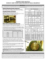
Shaft & <strong>Mount</strong>ing Surface Inspection<br />
Shaft should be smooth, straight & within commercial<br />
tolerances (Table 1). Remove burrs & align mounting<br />
surfaces within 2°.<br />
Table 1 - Shaft Tolerances<br />
Shaft Size (in) Commercial Shaft Tolerances (in)<br />
Up to 1 1/2” +0.000” / - 0.002”<br />
1 5/8” to 2 1/2” +0.000” / - 0.003”<br />
2 11/16” to 3 1/2” +0.000” / - 0.004”<br />
Assemble <strong>Adapter</strong> & Bearing<br />
If the locknut is loose from the bearing, FIRST place<br />
locknut into bearing inner ring groove, THEN insert adapter<br />
into bearing bore until it rests against the locknut.<br />
Rotate locknut clockwise to engage adapter sleeve.<br />
Pillow Blocks & Tapped Base Housings<br />
NOTE: For Tapped Base (TB) housings, drill mounting<br />
holes with 1/16” minimum bolt clearance to assist with<br />
proper installation.<br />
1. During installation it is best practice to remove all weight<br />
from the bearing via slings or jacks. However, if it is diffi cult<br />
to remove all weight, insure the dead weight on the bearing<br />
during installation does not exceed the values listed in Table 2.<br />
2. Slide the unit into position onto the shaft. If the unit will not<br />
slip onto the shaft, turn locknut counterclockwise to expand<br />
adapter sleeve.<br />
3. Wearing gloves, rotate locknut clockwise, by hand, as tight<br />
as possible until adapter sleeve does not spin on the shaft<br />
or move axially. If the locknut has been tightened as far as<br />
possible by hand and the assembly still slides or spins on<br />
the shaft then lightly tap on locknut outer diameter while<br />
WARNING: Because of the possible danger to persons(s) or property from accidents which may result from the improper use of products, it is<br />
important that correct procedures be followed. Products must be used in accordance with the engineering in<strong>for</strong>mation specified in the catalog.<br />
Proper installation, maintenance and operation procedures must be observed. The instructions in the instruction manuals must be followed.<br />
Inspections should be made as necessary to assure safe operation under prevailing conditions. Proper guards and other suitable safety devices or<br />
procedures as may be desirable or as may be specified in safety codes should be provided, and are neither provided by <strong>Baldor</strong> Electric Company nor<br />
are the responsibility of <strong>Baldor</strong> Electric Company. This unit and its associated equipment must be installed, adjusted and maintained by qualified<br />
personnel who are familiar with the construction and operation of all equipment in the system and the potential hazards involved. When risk to<br />
persons or property may be involved, a holding device must be an integral part of the driven equipment beyond the speed reducer output shaft.<br />
1<br />
continuing to turn locknut relative to the adapter sleeve by<br />
hand. After slight rotation (approx. 1/16 turn) of the locknut,<br />
recheck <strong>for</strong> adapter sleeve axial slip. Repeat this step as<br />
necessary. Scribe a line on the locknut above the adapter<br />
sleeve slot.<br />
Table 2 - Maximum Dead Load on<br />
Bearing During Installation<br />
Series Max Dead Load Per Bearing (lbs.)<br />
203-206 60<br />
207-210 65<br />
211-214 70<br />
215-218 75<br />
4. Lock bearing to shaft by rotating locknut, with a spanner<br />
wrench or drift & hammer, clockwise by amount shown in<br />
Table 3. Note: The use of air chisels is not recommended.<br />
Table 3 - Locknut Rotation from Handtight<br />
Series Shaft Size GT<br />
(Normal Duty)<br />
Shaft Size GTM<br />
(Medium Duty)<br />
Locknut<br />
Rotation<br />
203 - 204 1/2” - 3/4” --- 1/2 Turn<br />
205 - 209 7/8” 1 3/4”<br />
25 - 45 mm<br />
17 - 20 mm ---<br />
210 - 218 1 15/16” - 2 15/16”<br />
50 - 75 mm<br />
3/4” - 1 1/2”<br />
20 - 40 mm<br />
1 11/16” - 3 1/2”<br />
45 - 85 mm<br />
2/3 Turn<br />
1 Turn<br />
Center housing & mounting bolts over mounting holes & tighten<br />
bolts to proper torque (Table 4).<br />
<strong>Tight</strong>en locknut setscrew until 3/32” Allen key bends (25 in-lbs).
Metal Housings<br />
All Housing Types<br />
Bolt<br />
Size (in)<br />
Table 4 - <strong>Mount</strong>ing Bolt Torque (in-lbs)<br />
Dry<br />
Torque<br />
(in lbs)<br />
Non-Metallic Polymer Housing<br />
Pillow Block, 2 & 4<br />
Bolt Flange, Flange<br />
Bracket<br />
Bolt<br />
Size (in)<br />
Dry Torque<br />
(18-8<br />
Stainless<br />
(in lbs.)<br />
Tapped Base<br />
Bolt<br />
Size<br />
(in)<br />
3/8 240 3/8 225 3/8 175<br />
7/16 384 7/16 350 7/16 350<br />
1/2 600 1/2 500 1/2 400<br />
5/8 1200 9/16 650<br />
3/4 2100 5/8 1000<br />
7/8 2040<br />
Dry Torque<br />
(18-8<br />
Stainless)<br />
(in lbs)<br />
5. Repeat above steps <strong>for</strong> mounting 2nd housing. Do not tighten<br />
mounting bolts on 2nd housing until second bearing has been<br />
completely locked to the shaft. Bolts must fi t freely between<br />
housing & mounting surface. If the mounting bolts do not fit<br />
freely, loosen mounting bolts on both housings & center both<br />
units. If the bolts still do not fi t freely, remove one unit from<br />
the shaft, reposition housing & reinstall.<br />
All Flange Housing<br />
Note: Special attention to the installation procedure <strong>for</strong> flange<br />
bearings is necessary to maintain the proper internal clearance<br />
& achieve maximum life. The installation of the first flange differs<br />
from the installation of the second flange.<br />
1. Follow instructions under Assemble <strong>Adapter</strong> & Bearing section<br />
on page 1.<br />
2. During installation, it is best practice to remove all weight<br />
from the bearing via slings or jacks. However, if it is diffi cult<br />
to remove all weight, insure the dead weight on the bearing<br />
during installation does not exceed the values listed in Table 2.<br />
3. Slide the FIRST fl ange into position onto the shaft. If the<br />
bearing will not slip onto the shaft, turn locknut counter<br />
clockwise to expand adapter sleeve.<br />
4. Wearing gloves, rotate locknut clockwise, by hand, as tight<br />
as possible until adapter sleeve does not spin on the shaft<br />
or move axially. If the locknut has been tightened as far as<br />
possible by hand and the assembly still slides or spins on<br />
the shaft then lightly tap on locknut outer diameter while<br />
continuing to turn locknut relative to the adapter sleeve by<br />
hand. After slight rotation (approx. 1/16 turn) of the locknut,<br />
recheck <strong>for</strong> adapter sleeve axial slip. Repeat this step as<br />
necessary. Scribe a line on the locknut above the adapter<br />
sleeve slot.<br />
5. This is the starting point. Scribe a line on the locknut above<br />
the adapter sleeve slot. Lock bearing to shaft by rotating<br />
locknut, with a spanner wrench or drift & hammer, clockwise<br />
by amount shown in Table 3.<br />
NOTE: The use of air chisels is not recommended.<br />
6. <strong>Tight</strong>en locknut setscrew until 3/32” Allen key bends<br />
(25 in-lbs). <strong>Tight</strong>en housing bolts to proper torque (Table 4).<br />
7. Slide the SECOND fl ange onto the shaft and hand tighten as<br />
in step 4 but leave 1/16” minimum gap between the fl ange<br />
housing & the mounting surface.<br />
8. It is important to note that the 1/16” minimum gap between<br />
the fl ange housing and the mounting surface must be<br />
maintained while getting the bearing hand tight to the shaft.<br />
Wearing gloves, rotate the locknut clockwise, by hand, until<br />
adapter sleeve grips and does not spin or move axially on<br />
the shaft. If needed, tap on the locknut outer diameter while<br />
turning the locknut to assist with this step. At this point you<br />
should have diffi culty in rotating the locknut by hand and you<br />
should not be able to move the bearing axially along the shaft<br />
by hand. If the bearing can be moved axially along the shaft by<br />
2<br />
hand then continue rotating the nut gradually until it grips the<br />
shaft. Scribe a line on the locknut above the adapter sleeve<br />
slot.<br />
9. Insert housing bolts & pull the housing flush with mounting<br />
surface by alternately tightening the bolts to the proper torque<br />
(Table 4).<br />
10. Lock bearing to shaft by rotating locknut, with a spanner<br />
wrench or drift & hammer, clockwise by amount shown in<br />
Table 3. <strong>Tight</strong>en locknut setscrew until 3/32” Allen key bends<br />
(25 in-lbs).<br />
11. Rotate the shaft by hand, no binding or excessive drag<br />
should be felt. If excessive drag is felt, loosen the second<br />
bearing & reinstall starting at step 8.<br />
Wide Slot and Narrow Slot Take-Up<br />
Housings<br />
Note: Special attention to the installation procedure <strong>for</strong> WSTU<br />
and NSTU bearings is necessary to maintain the proper internal<br />
clearance & achieve maximum life. The installation of the first<br />
bearing differs from the second bearing.<br />
1. If the locknut is loose from the bearing, FIRST place locknut<br />
into bearing inner ring groove, THEN insert adapter into<br />
bearing bore until it rests against the locknut. Rotate locknut<br />
clockwise to engage adapter sleeve.<br />
2. During installation it is best practice to remove all of the<br />
weight from the bearing via slings or jacks. However, if it is diffi<br />
cult to remove all weight then insure the dead weight on the<br />
bearing during installation does not exceed the values listed in<br />
Table 2.<br />
3. Slide both bearing units into position onto the shaft and into<br />
the frame and attach bearings to frame screw. If the bearing<br />
will not slip onto the shaft or move axially, turn locknut counter<br />
clockwise to expand adapter sleeve.<br />
4. Start with the complete installation of the first bearing.<br />
Wearing gloves, rotate locknut clockwise, by hand, as tight<br />
as possible until adapter sleeve does not spin on the shaft<br />
or move axially. If the locknut has been tightened as far as<br />
possible by hand and the assembly still slides or spins on<br />
the shaft then lightly tap on locknut outer diameter while<br />
continuing to turn locknut relative to the adapter sleeve by<br />
hand.<br />
After slight rotation (approx. 1/16 turn) of the locknut, recheck<br />
<strong>for</strong> adapter sleeve axial slip. Repeat this step as necessary.<br />
Scribe a line on the locknut above the adapter sleeve slot.<br />
5. Lock bearing to shaft by rotating locknut, with a spanner<br />
wrench or brass bar & hammer, clockwise by amount shown in<br />
Table 3. Note the use of air chisels is not recommended.<br />
6. <strong>Tight</strong>en locknut setscrew until 3/32” Allen key bends<br />
(25 in-lbs).<br />
7. Once the fi rst bearing has been installed, insert a shim<br />
(outlined in Table 6) between the guide rail and housing slot<br />
on the side of the rail CLOSEST to the locknut. To present<br />
the bearing from being cocked, install a shim at both top and<br />
bottom rails, between each TURF rail and TU housing on the<br />
locknut side as shown in the figure below. Shim housing until<br />
rail and slot are snug against each other.
GT COLLAR<br />
SHIM<br />
SHIM<br />
8. Begin the installation of the second TU by inserting a shim<br />
between the guide rail and housing slot on the side of the rail<br />
CLOSEST to the locknut. Install a shim on both the top and<br />
bottom of the TU rails as shown in the fi gure above. Use the<br />
same shim thickness and procedure that was used in step 7.<br />
The shims are used to push the bearing housing away from<br />
each other so they have room to move up the tapered adapter<br />
sleeve during the installation process of the 2nd bearing.<br />
By shimming the bearing housing out, the bearings will end<br />
up mid-center on the TUFR rail after installation of the 2nd<br />
bearing.<br />
9. Wearing gloves, rotate locknut clockwise, by hand, as tight<br />
as possible until adapter sleeve does not spin on the shaft<br />
or move axially. If the locknut has been tightened as far as<br />
possible by hand and the assembly still slides or spins on<br />
the shaft then lightly tap on locknut outer diameter while<br />
continuing to turn locknut relative to the adapter sleeve by<br />
hand. After slight rotation (approx. 1/16 turn) of the locknut,<br />
recheck <strong>for</strong> adapter sleeve axial slip. Repeat this step as<br />
necessary. Scribe a line on the locknut above the adapter<br />
sleeve slot.<br />
10. Remove the shims from both bearings.<br />
11. Lock second bearing to shaft by rotating locknut with a<br />
spanner wrench or drift pin & hammer, clockwise by amount<br />
shown in Table 3. <strong>Tight</strong>en locknut setscrew until 3/32” Allen<br />
key bends (25 in-lbs).<br />
12. Rotate the shaft by hand, no binding or excessive drag<br />
should be felt. If excessive drag is felt, loosen the second<br />
bearing & reinstall starting at step 7.<br />
3<br />
Dismounting All Units<br />
1. Remove all weight from the bearing via slings or jacks &<br />
secure the shaft from rotation.<br />
2. LOOSEN THE HOUSING MOUNTING BOLTS & COMPLETELY<br />
REMOVE SETSCREW IN THE LOCKNUT.<br />
3. Rotate locknut counter clockwise with spanner wrench or drift<br />
& hammer until bearing is free.<br />
Lubrication<br />
This bearing is factory lubricated with a lithium or lithium<br />
complex* base grease which is suitable <strong>for</strong> most applications.<br />
However, extra protection is necessary if the bearing is<br />
subjected to excessive moisture, dust, corrosive vapor or<br />
other harsh environments. In these cases, the bearing should<br />
contain as much grease as speed will permit (a full bearing<br />
with consequent slight leakage through the seal is the best<br />
protection against contaminant entry).<br />
For relubrication, select a grease that is compatible with a<br />
lithium or lithium complex* grease. The following table is a<br />
general guide <strong>for</strong> normal operating conditions. However, some<br />
situations may require a change in lubricating periods as<br />
dictated by experience. Generally, a lower quantity of grease<br />
at frequent intervals is more effective than a greater quantity at<br />
extended lubrication intervals.<br />
Lubrication recommendations are intended <strong>for</strong> standard<br />
products applied in general operating conditions.<br />
For modified products, high temperature environments and<br />
other applications, refer to www.dodge-pt.com<br />
NOTE: Dodge EZ Kleen ball bearing product line is lubricated<br />
with an aluminum complex base grease.<br />
Table 5 - Suggested Lubrication Intervals in Weeks<br />
Hours<br />
Run<br />
Per<br />
Day<br />
1<br />
to<br />
250<br />
RPM<br />
251<br />
to<br />
500<br />
RPM<br />
501<br />
to<br />
750<br />
RPM<br />
751<br />
to<br />
1000<br />
RPM<br />
RPM<br />
1001<br />
to<br />
1500<br />
RPM<br />
1501<br />
to<br />
2000<br />
RPM<br />
2001<br />
to<br />
2500<br />
RPM<br />
8 12 12 10 7 5 4 3 3<br />
16 12 7 5 4 2 2 1 1<br />
24 10 5 3 2 1 1 1 1<br />
Table 6 - Approximate Shim Thickness Required<br />
Bearing Type Shaft Diameter Shim Thickness<br />
Narrow Slot GT/GTM All 0.060”<br />
Wide Slot GT Up to 1-7/16” or 35mm 0.030”<br />
Wide Slot GT Larger than 1-7/16” or 35mm 0.060”<br />
Wide Slot GTM Up to 1-1/4 or 30mm 0.030”<br />
Wide Slot GTM Larger than 1-1/4” or 30mm 0.060”<br />
2500<br />
to<br />
Max<br />
RPM
© <strong>Baldor</strong> Electric Company<br />
MN3004 (Replaces 499312)<br />
World Headquarters<br />
P.O. Box 2400, Fort Smith, AR 72902-2400 U.S.A., Ph: (1) 479.646.4711, Fax (1) 479.648.5792, International Fax (1) 479.648.5895<br />
Dodge Product Suport<br />
6040 Ponders Court, Greenville, SC 29615-4617 U.S.A., Ph: (1) 864.297.4800, Fax: (1) 864.281.2433<br />
www.baldor.com<br />
All Rights Reserved. Printed in USA.<br />
08/01/09