Surgical Technique International Version
Surgical Technique International Version
Surgical Technique International Version

You also want an ePaper? Increase the reach of your titles
YUMPU automatically turns print PDFs into web optimized ePapers that Google loves.
<strong>Surgical</strong> <strong>Technique</strong><br />
<strong>International</strong> <strong>Version</strong>
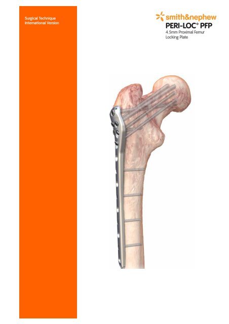
PERI-LOC PFP<br />
4.5mm Proximal Femur Locking Plate<br />
<strong>Surgical</strong> <strong>Technique</strong><br />
Table of contents<br />
Product overview ..............................................................................2<br />
Introduction..........................................................................................2<br />
Indications ..........................................................................................3<br />
Case examples....................................................................................4<br />
Design features and benefits ..............................................................5<br />
PERI-LOC PFP implant overview........................................................6<br />
<strong>Surgical</strong> technique ............................................................................8<br />
Patient positioning ..............................................................................8<br />
Fracture reduction and provisional fixation ........................................8<br />
Plate selection ....................................................................................9<br />
Plate positioning ..................................................................................9<br />
Open technique ................................................................................10<br />
Alpha hole Guide Pin insertion ..........................................................10<br />
Angular adjustment ............................................................................12<br />
Beta hole Guide Pin insertion ............................................................14<br />
Screw insertion ..................................................................................15<br />
6.5mm Cannulated Screw ................................................................15<br />
5.7mm Cannulated Screw ................................................................16<br />
4.5mm Cortex Screw ........................................................................17<br />
4.5mm Locking Screw ......................................................................18<br />
Cable Saddles and Hole Filler ..........................................................19<br />
Percutaneous technique ................................................................20<br />
Radiolucent Targeter assembly..........................................................20<br />
Plate insertion and provisional fixation ............................................21<br />
Alpha hole Guide Pin insertion..........................................................22<br />
Plate repositioning ............................................................................22<br />
Beta hole Guide Pin insertion ............................................................23<br />
Screw insertion ..................................................................................24<br />
6.5mm Cannulated Screw ................................................................24<br />
5.7mm Cannulated Screw ................................................................25<br />
4.5mm Cortex and Locking Screw ....................................................26<br />
Targeter removal ................................................................................27<br />
Closure ................................................................................................28<br />
Catalogue information ......................................................................29<br />
Nota Bene<br />
The technique description herein is made available to the healthcare professional to illustrate<br />
the author’s suggested treatment for the uncomplicated procedure. In the final analysis, the<br />
preferred treatment is that which addresses the needs of the specific patient.<br />
1
Product overview<br />
Introduction<br />
Proximal femur fractures are challenging injuries<br />
that are prone to a variety of complications.<br />
Factors such as rotational instability, the<br />
presence of varied fracture patterns and<br />
complex deforming forces, and the frequent<br />
association of these fractures with comminution<br />
and/or poor bone quality require dedicated<br />
implants for optimal fracture fixation.<br />
The PERI-LOC PFP 4.5mm Proximal Femur<br />
Locking Plate offers a total of six individual<br />
screw options in the proximal femur for<br />
superior stability and intraoperative versatility.<br />
An anatomically bowed shaft maximises<br />
plate-to-bone coverage extending down the<br />
shaft of the femur for an optimal anatomic<br />
implant fit. The minimally invasive procedure is<br />
facilitated by a radiolucent targeting system<br />
designed to reduce the potential for soft tissue<br />
damage or disruption of blood supply.<br />
The PERI-LOC Locked Plating System combines<br />
the advantages of locked plating with the<br />
flexibility and benefits of traditional plates and<br />
screws. Utilising both locking and non-locking<br />
screws, the PERI-LOC system allows for the<br />
creation of a fixed-angle construct capable<br />
of resisting angular collapse and rotational<br />
displacement. Its enhanced stability also allows<br />
it to function as an effective fracture reduction<br />
aid. A simple, intuitive instrument set featuring<br />
standardised drill bits and screwdrivers along<br />
with colour-coded Drill Guides helps make the<br />
PERI-LOC system efficient and easy to use.<br />
With its multiple points of fixation and anatomic<br />
plate design, the PERI-LOC 4.5mm Proximal<br />
Femur Locking Plate (PFP) is geared towards<br />
superior fixation of challenging proximal<br />
femur fractures.<br />
All PERI-LOC PFP implants are manufactured<br />
using the highest quality 316L stainless steel<br />
for strength and durability.<br />
2
Indications<br />
The PERI-LOC 4.5mm Proximal Femur Locking<br />
Plate is indicated for the treatment of:<br />
•Fractures of the trochanteric region<br />
including simple intertrochanteric, reverse<br />
intertrochanteric, transverse trochanteric,<br />
complex multifragmentary and fractures<br />
with medial cortex instability<br />
•Proximal femur fractures with ipsilateral<br />
shaft fractures<br />
•Metastatic proximal femur fractures<br />
•Proximal femur osteotomies<br />
•Fractures in osteopenic bone<br />
•Non-unions and malunions<br />
•Basi/transcervical femoral neck fractures<br />
•Subcapital femoral neck fractures<br />
•Subtrochanteric femur fractures<br />
3
PERI-LOC Proximal Femur case examples<br />
Post-operative radiographs<br />
4
Design features and benefits<br />
Multiple fixation points<br />
Each PERI-LOC 4.5mm Proximal Femur Locking<br />
Plate offers up to six points of fixation in the<br />
proximal femur. Five screws support the<br />
femoral neck and head and one targets the<br />
calcar femorale. Multiple points of fixation<br />
optimise the implant’s ability to resist rotational<br />
and varus stresses through the trochanteric<br />
region. Screws may be inserted in either<br />
locking or non-locking mode to allow for the<br />
creation of customisable hybrid locked<br />
plating constructs.<br />
Anatomical plate design<br />
The head of the 4.5mm Proximal Femur<br />
Locking Plate is precontoured to fit the<br />
anatomy of the lateral aspect of the greater<br />
trochanter. Extending down the shaft of the<br />
femur, the plate sits straight along the lateral<br />
cortex with an anterior curve beginning at the<br />
six-hole plate option. This anterior curve<br />
provides an anatomic plate fit to ensure<br />
optimal plate position on bone. Left and right<br />
Proximal Femur Locking Plate versions are the<br />
natural result of an anatomically contoured<br />
plate design.<br />
Minimally invasive<br />
A radiolucent targeter is available for<br />
percutaneous fixation of proximal femur<br />
fractures. The targeter is comprised of two<br />
parts, a base segment for short plates and an<br />
extension that matches the anatomic contour<br />
of the plate to ensure precision targeting of<br />
the distal holes in longer plates. Standard<br />
PERI-LOC radiolucent targeter instrumentation<br />
facilitates streamlined minimally invasive<br />
fixation of proximal femur fractures.<br />
5
PERI-LOC PFP implant overview<br />
PERI-LOC 4.5mm Proximal Femur<br />
Locking Plate<br />
• Anatomically contoured to the lateral aspect<br />
of the proximal femur<br />
• Left and right specific<br />
• Six distinct points of fixation in the<br />
proximal femur<br />
• Bullet plate tip assists with percutaneous<br />
insertion and minimises prominence<br />
• Locking or non-locking option in every<br />
screw hole<br />
• Each screw hole accepts 4.5mm Cortex,<br />
4.5mm Locking, 5.7mm Cannulated Locking,<br />
6.5mm Cancellous, 6.5mm Cannulated Conical<br />
and/or 6.5mm Cannulated Locking Screws<br />
• 2.3 metre anatomic bow beginning at the sixth<br />
hole to maximise plate coverage extending<br />
down the femoral shaft<br />
• Radiolucent targeter available for percutaneous<br />
fracture fixation<br />
• Compatible with the PERI-LOC Large Fragment<br />
Locked Plating System<br />
• Manufactured from 316L stainless steel for<br />
strength and durability<br />
6
PERI-LOC PFP Screws<br />
• Low-profile heads to reduce soft tissue irritation<br />
• Self-Tapping 4.5mm Cortex and 4.5mm<br />
Locking Screws<br />
• Self-Drilling, Self-Tapping 5.7mm Cannulated<br />
Locking, 6.5mm Cannulated Conical and<br />
6.5mm Cannulated Locking Screws<br />
• Manufactured from 316L stainless steel for<br />
strength and durability<br />
PERI-LOC PFP Cable Saddle<br />
• Holds cable in position around a plate<br />
• Snap-fits into 4.5mm and 5.7mm screws<br />
• No drilling required<br />
• System compatibility:<br />
Standard ACCORD Cable System implants<br />
and all cable systems using up to a 2.0mm<br />
diameter stainless steel cable<br />
• Manufactured from 316L stainless steel for<br />
strength and durability<br />
New 6.5mm<br />
Cannulated Screws<br />
Cable Saddle<br />
7
<strong>Surgical</strong> technique<br />
Patient positioning<br />
Place the patient in the supine or lateral<br />
position on a radiolucent surgical table<br />
according to surgeon preference and fracture<br />
pattern. If using a fracture table, the foot of the<br />
affected limb is placed in a foot holder or a<br />
skeletal traction pin is used to achieve traction.<br />
The unaffected limb is extended down and<br />
away from the affected limb or placed up in a<br />
leg holder.<br />
Check the affected limb for length and rotation<br />
by comparison to the unaffected limb. Rotate<br />
the C-Arm to ensure optimal AP and lateral<br />
visualisation of the proximal femur.<br />
Note If using a radiolucent surgical table, a<br />
distraction device may be helpful in reducing<br />
the fracture.<br />
Fracture reduction and<br />
provisional fixation<br />
Obtain gross skeletal alignment using applied<br />
traction, reduction forceps, a ball spike pusher,<br />
half pins or other conventional methods of<br />
reduction. Provisionally secure fracture<br />
fragments using 2.0mm K-wires or reduction<br />
forceps. Reduction aids should be placed so<br />
as not to interfere with final plate placement.<br />
8
Plate selection<br />
Following fracture reduction, select the<br />
4.5mm Proximal Femur Locking Plate that<br />
best accommodates patient anatomy and<br />
fracture pattern. The PERI-LOC 4.5mm<br />
Proximal Femur Locking Plate Pre-operative<br />
Template is available to assist with<br />
preoperative radiographic planning. Plate<br />
and screw length may be determined.<br />
Note As template magnification levels are set<br />
at 117%, all measurements are estimates of<br />
true size. All implant measurements must be<br />
verified intraoperatively.<br />
Plate positioning<br />
Position the PERI-LOC 4.5mm Locking Proximal<br />
Femur Plate against the lateral aspect of the<br />
greater trochanter. Extending distally, the plate<br />
will line up along the lateral cortex of the<br />
femoral shaft. Thread a 3.2mm Drill Guide into<br />
the designated “Alpha” hole on the plate*.<br />
The 4.5mm Proximal Femur Locking Plate may<br />
be provisionally fixed to the proximal femur<br />
using 3.2mm Drill Tip Guide Pins and then<br />
compressed to the femoral shaft using<br />
reduction forceps and/or Provisional Fixation<br />
Pins. The Alpha hole serves as the designated<br />
point of reference for correct plate position<br />
within the proximal fragment and initial Guide<br />
Pin insertion. The Drill Guide can also be<br />
used as a handle to aid in positioning<br />
the plate.<br />
Note The 3.2mm Drill Guide has a hex recess<br />
that will accept a 4.7mm Hexdriver. This may<br />
be helpful in Drill Guide removal and during<br />
plate positioning.<br />
Note Based on patient anatomy and plate<br />
position, not all proximal screws options may<br />
be used.<br />
*If inserting the plate using the open technique<br />
PERI-LOC 4.5mm Lateral Proximal Femur<br />
Locking Plate Pre-operative Template<br />
Beta hole<br />
Alpha hole<br />
9
Open technique<br />
Alpha hole Guide Pin insertion<br />
Thread the 3.2mm Drill Guide (7117-6753)<br />
into the Alpha hole of the proximal femur<br />
locking plate.<br />
Verify the plate position on the greater<br />
trochanter in both the AP and lateral views.<br />
Attach a 3.2mm Drill Tip Guide Pin (7117-5704)<br />
to power via the Mini Connect Adaptor and<br />
insert into the femoral head through the Drill<br />
Guide to the desired depth.<br />
Optimal Guide Pin position is just superior to<br />
the calcar (AP view) and in-line with the<br />
femoral neck axis (AP and lateral views). The<br />
Guide Pin should be inserted to the desired<br />
depth, but should not penetrate the<br />
subchondral bone of the femoral head.<br />
Note If the plate and Guide Pin are in the<br />
desired position, proceed to Beta hole Guide<br />
Pin insertion section (page 14).<br />
In the instance of sub-optimal Guide Pin<br />
placement, reposition as follows:<br />
•Remove the 3.2mm Guide Pin<br />
•Reposition the PERI-LOC Proximal Femur Plate<br />
on the greater trochanter<br />
•Repeat the steps for Alpha hole guide<br />
pin insertion<br />
The PERI-LOC Proximal Femur Locking Plate<br />
may also be positioned using an Adjustable<br />
Drill Guide in the event that optimal Guide Pin<br />
placement proves difficult.<br />
10
Adjustable guide option for<br />
Guide Pin insertion<br />
Assemble the Adjustable Guide Pin Sleeve<br />
(7117-6767) by inserting the Adjustable Guide<br />
Pin Insert into the centre slot of the Guide Pin<br />
Sleeve (7117-6768). The adjustable drill guide<br />
provides controlled means to adjust the<br />
trajectory of the guide pin insertion. It is<br />
recommended that the Alpha hole guide pin<br />
be placed and optimised first. With the Guide<br />
Pin Sleeve threaded into a screw hole, the<br />
Guide Pin Insert can be positioned within the<br />
Guide Pin Sleeve to achieve either on-axis or<br />
3° or 6° of off-axis guide pin insertion.<br />
Note Off-axis guide pin insertion is used<br />
only for plate repositioning on the proximal<br />
femur. It is not an indication of polyaxial<br />
plate capabilities.<br />
Adjustable guide technique for Alpha Guide<br />
Pin insertion<br />
Thread the Adjustable Guide Pin Sleeve into<br />
the Alpha hole of the proximal femur plate<br />
using the 4.7mm Hexdriver with Handle.<br />
Ensure that the hexdriver is in the centre<br />
position of the Guide Pin Sleeve.<br />
Insert the Guide Pin Insert into the desired<br />
position of the Guide Pin Sleeve and rotate<br />
until the flats on the insert are perpendicular<br />
to the sleeve. This will lock the insert<br />
into place.<br />
Attach a 3.2mm Drill Tip Guide Pin (7117-5704)<br />
to power via the Mini Connect Adaptor and<br />
advance through the Adjustable Guide Pin<br />
Insert to the desired depth. Verify plate<br />
position on the greater trochanter in the<br />
AP view.<br />
Optimal Guide Pin position is just superior<br />
to the calcar (AP view) and in-line with the<br />
femoral neck axis (AP and lateral views). The<br />
Guide Pin should be inserted to the desired<br />
depth, but should not penetrate the<br />
subchondral bone of the femoral head.<br />
4.7mm hex<br />
3.2mm Sleeve<br />
Insert<br />
Body<br />
Threaded tip<br />
11
In the lateral view, verify the correct femoral<br />
neck anteversion and 3.2mm Guide<br />
Pin placement.<br />
Note If the plate and Guide Pin are in the<br />
desired position, proceed to Beta hole Guide<br />
Pin insertion section (page 14).<br />
In the instance of sub-optimal Guide Pin<br />
placement, reposition either using free-hand<br />
technique and/or by using the Angular<br />
Adjustment Guide.<br />
Angular adjustment guide technique<br />
Thread a 3.5mm Drill Guide (7117-3451) into<br />
both the most proximal and second or third<br />
from most distal screw holes of the plate.<br />
Attach a 3.5mm x 18mm Provisional Fixation<br />
Pin (7117-5706) to power via the Quick Connect<br />
Adaptor and insert one into each 3.5mm<br />
Drill Guide.<br />
Note Advance the provisional fixation pin<br />
on power, but tighten by hand using a<br />
T-Handle to avoid stripping the pin and/or<br />
loss of reduction.<br />
With the plate provisionally fixed to bone,<br />
remove the sub-optimal 3.2mm Guide Pin.<br />
Unlock the Guide Pin Insert by rotating the<br />
sleeve until the flats are parallel with the slot<br />
in the Guide Pin Sleeve. Adjust and lock the<br />
sleeve insert into either the 3° or 6° offset<br />
position, depending on the desired final guide<br />
pin placement.<br />
12
Advance the 3.2mm Drill Tip Guide Pin<br />
through the repositioned sleeve insert as<br />
previously described. Verify the Guide Pin<br />
position in both the AP and lateral views.<br />
If satisfied with Guide Pin position, remove<br />
both provisional fixation pins from the 3.5mm<br />
Drill Guides. Unlock the Guide Pin Insert by<br />
rotating the Guide Pin Insert until the flats are<br />
parallel with the slot in the Guide Pin Sleeve.<br />
Reposition the plate so that the sleeve insert is<br />
in the centre of the Adjustable Guide Pin<br />
Sleeve and lock in place. The 3.5mm Drill<br />
Guides may be left in place to serve as<br />
handles during repositioning.<br />
Re-insert the 3.5mm x 18mm Provisional<br />
Fixation Pin into the distal-most 3.5mm Drill<br />
Guide as previously described.<br />
13
Beta hole Guide Pin insertion<br />
Thread a 3.2mm Drill Guide into the most<br />
superior/posterior hole in the proximal portion<br />
of the plate (Beta hole). Insert a 3.2mm Drill<br />
Tip Guide Pin through the Drill Guide to the<br />
desired depth. Verify guide pin position in<br />
both the AP and lateral views.<br />
Note Always ensure that at least two Guide<br />
Pins have been inserted into the proximal<br />
femur before proceeding with screw insertion.<br />
These guide pins will help control any<br />
rotational instability.<br />
Note A 4.5mm x 80mm Provisional Fixation<br />
Pin (7117-5705) may be inserted through the<br />
Beta hole in place of the 3.2mm Guide Pin if<br />
fracture compression or plate-to-bone<br />
reduction is desired prior to screw insertion.<br />
This requires a 4.5mm Drill Guide (7117-3541)<br />
in place of the 3.2mm version.<br />
Determine which screws are most appropriate<br />
for fracture fixation. A combination of 4.5mm<br />
Cortex, 4.5mm Locking, 5.7mm Cannulated<br />
Locking, 6.5mm Cancellous, 6.5mm<br />
Cannulated Conical and 6.5mm Cannulated<br />
Locking Screws may be used. It is<br />
recommended that screw insertion begin with<br />
the Alpha hole before proceeding further.<br />
Note It is recommended that all guide pins for<br />
remaining proximal screws be inserted and<br />
verified under fluoroscopy in both the AP and<br />
lateral views to confirm position prior to<br />
proceeding with screw insertion.<br />
14
Screw insertion<br />
6.5mm Cannulated Screw insertion<br />
Measure for screw length by reading the<br />
exposed calibrations off the 3.2mm Drill Tip<br />
Guide Pin or by sliding the 6.5mm Cannulated<br />
Depth Gauge (7117-6770) over the guide pin to<br />
the back of the Guide Pin Insert.<br />
Remove the Adjustable Guide Pin Sleeve and<br />
Insert. Attach the 4.7mm Cannulated Hexdriver<br />
(7117-7161) to power via the Large Quick<br />
Connect Adaptor and insert the appropriate<br />
length 6.5mm Cannulated Conical or<br />
Cannulated Locking Screw over the 3.2mm<br />
Drill Tip Guide Pin. Alternatively, screws may<br />
be inserted by hand using the Quick Connect<br />
T-Handle (7117-7204).<br />
Note Screws may be inserted on power, but<br />
should always be tightened by hand in order<br />
to avoid loss of reduction, stripping of the<br />
screw head or damage to the screwdriver.<br />
Note The self-drilling/tapping design of the<br />
6.5mm Cannulated Conical and Locking<br />
Screws renders pre-drilling and tapping<br />
for the screw unnecessary in most instances.<br />
However, if encountering hard bone, it<br />
may be useful to drill and/or tap prior to<br />
screw insertion*.<br />
*5.0mm Cannulated Drill Bit (7117-7134) and 6.5mm Cannulated Screw Tap (7117-7143)<br />
15
5.7mm Cannulated Locking Screw insertion<br />
Thread the 4.5mm Locking Screw Guide<br />
(7117-3541) into the desired screw hole and<br />
insert and drill with the 4.5mm Drill Bit<br />
(7117-3506) to the desired depth. Verify drill bit<br />
placement in both the AP and lateral views.<br />
Calibrations on side of drill will determine<br />
screw length.<br />
Note Due to the density of the bone in the<br />
proximal femur and the likelihood of pin<br />
skiving, it is recommended that 2.0mm<br />
K-wires not be used.<br />
Remove the 4.5mm Drill Bit and 4.5mm<br />
Locking Drill Guide.<br />
Attach the 3.5mm Hexdriver (7117-3537) to<br />
power via the Connector and insert the<br />
appropriate length 5.7mm Cannulated<br />
Locking Screw. Alternatively, screws may be<br />
inserted by hand using the Large Quick<br />
Connect Handle.<br />
Note Screws may be inserted on power, but<br />
should always be tightened by hand in order<br />
to avoid loss of reduction, stripping of the<br />
screw head or damage to the screwdriver.<br />
16
4.5mm Cortex Screw<br />
Insert the Universal Drill Guide Handle<br />
(7117-3349) with 3.5mm Neutral Locking Hole<br />
Insert (7117-3521) into the desired screw hole<br />
in the plate shaft and drill accordingly with<br />
Short 3.5mm Drill Bit (7117-3504). If inserting a<br />
4.5mm Cortex Screw into the proximal portion<br />
of the plate, it is recommended that the Long<br />
3.5mm Drill Bit (7117-3505) be used.<br />
Measure for screw length by reading the<br />
exposed calibrations off the drill bit or by using<br />
the Large Screw Depth Gauge (7117-3331).<br />
Insert the appropriate length 4.5mm Cortex<br />
Screw using the 3.5mm Hexdriver Shaft<br />
(7117-3537) and Large Quick Connect Handle.<br />
Note Screws may be inserted on power, but<br />
should always be tightened by hand in order<br />
to avoid loss of reduction, stripping of the<br />
screw head or damage to the screwdriver.<br />
17
4.5mm Locking Screw<br />
Thread a 3.5mm Locking Drill Guide<br />
(7117-3451) One-Piece* into the desired screw<br />
hole in the plate and drill accordingly with the<br />
Short 3.5mm Drill Bit.<br />
Note If inserting a 4.5mm Locking Screw<br />
into the proximal portion of the plate, it is<br />
recommended that the Long 3.5mm Drill Bit<br />
be used.<br />
Measure for screw length by reading the<br />
exposed calibrations off the drill bit or by using<br />
the Large Screw Depth Gauge.<br />
Insert the appropriate length 4.5mm Locking<br />
Screw using the 3.5mm Hexdriver Shaft and<br />
Large Quick Connect Handle.<br />
Note Screws may be inserted on power, but<br />
should always be tightened by hand in order<br />
to avoid loss of reduction, stripping of the<br />
screw head, or damage to the screwdriver.<br />
Fill remaining screw holes as desired.<br />
*The 4.5mm Locking Screw Guide (7117-3539) with 3.5mm Locking Guide Insert (7117-3530) may be used in place of the 3.5mm Locking Drill Guide One-Piece<br />
18
Cable Saddle and Hole Filler<br />
The Hole Filler (7480-0603) may be added to<br />
any screw hole in the PERI-LOC Proximal<br />
Femur Locking Plate as desired.<br />
Insert the Hole Filler using the 3.5mm<br />
Hexdriver Shaft and Large Quick<br />
Connect Handle.<br />
The Cable Saddle (7480-0601 or 7480-0602) is<br />
compatible with any stainless steel cables<br />
between 1.6mm and 2.0mm. Attach the Cable<br />
Saddle to the Cable Saddle Insertion Tool<br />
(7117-6766). Insert the Cable Saddle using the<br />
insertion tool into any desired Hole Filler or the<br />
head of an inserted screw.<br />
The cable can be threaded into the Cable<br />
Saddle with the insertion tool still attached.<br />
Proceed accordingly with cable application as<br />
described in the particular technique.<br />
19
Percutaneous technique using<br />
radiolucent targeter<br />
Radiolucent Targeter assembly<br />
Assemble the PERI-LOC Targeter Handle<br />
(7117-6748 Left or 7117-6749 Right) to the<br />
selected plate by threading the 4.5mm Drill<br />
Guide through the handle into the most<br />
proximal hole until tight. For final tightening,<br />
rotate the locking nut clockwise using the<br />
Locking Tool (7117-6746). Attach the<br />
corresponding Targeter Base to the handle<br />
(7117-6750 or 7117-6751). Verify targeter<br />
assembly by inserting a PERI-LOC Targeter<br />
3.5mm Drill Guide (7117-3382) into a PERI-LOC<br />
Targeter 4.5mm Screw Guide (7117-3397) and<br />
passing the assembly through the most distal<br />
hole in the base.<br />
The targeter extension (7117-6752) is required<br />
for 12-hole plates and longer. Tighten the<br />
assembly to the plate and pass a Long 3.5mm<br />
Drill Bit through the drill guide. Remove the<br />
screw/drill guide assembly and targeter base<br />
prior to plate insertion.<br />
20
Plate insertion and provisional fixation<br />
Insert the plate through the incision using the<br />
attached handle as an insertion aid. Slide the<br />
plate down the shaft of the femur between<br />
muscle and periosteum keeping the distal tip<br />
of the plate against bone. Confirm plate<br />
position under fluoroscopy in the AP and<br />
lateral views.<br />
Attach a 3.5mm x 18mm Provisional Fixation<br />
Pin (7117-5703) to power via the Quick<br />
Connector and insert through the drill guide<br />
of the superior most hole. Tighten the pin by<br />
hand using the Quick Connect Handle to avoid<br />
stripping the pin. Attach the appropriate<br />
targeter base to the handle.<br />
Note It is acceptable to use a 3.5mm<br />
Provisional Fixation Pin proximally with the<br />
4.5mm Drill Guide.<br />
Note For plates 12 holes in length and longer,<br />
a targeter extension will be required for<br />
percutaneous targeting of all plate holes.<br />
With the plate provisionally secured to bone<br />
proximally, make a stab incision over the<br />
second or third most distal screw hole in line<br />
with the targeter base. Insert a Trocar (7117-<br />
3404) into a 4.5mm Screw Guide and pass the<br />
assembly through the targeter base into the<br />
plate. Remove the trocar from the screw guide<br />
and replace it with a 3.5mm Drill Guide.<br />
Thread the drill guide into the plate until tight.<br />
Insert a 3.5mm x 18mm Provisional Fixation Pin<br />
through the drill guide and tighten as<br />
previously described.<br />
21
Alpha hole Guide Pin insertion<br />
Insert a 3.2mm Drill Guide (7117-6745) into a<br />
4.5mm Screw Guide, pass the assembly<br />
through the targeter and thread into the Alpha<br />
hole until tight. Attach a 3.2mm Drill Tip Guide<br />
Pin (7117-5701) to power via the Mini Connector<br />
and insert through the drill guide to the<br />
desired depth in the femoral neck and head.<br />
Verify Guide Pin position under fluoroscopy in<br />
both the AP and lateral views.<br />
Optimal Guide Pin position is just superior to<br />
the calcar (AP view) and in-line with the<br />
femoral neck axis (AP and lateral views). The<br />
Guide Pin should be inserted to the desired<br />
depth, but should not penetrate the<br />
subchondral bone of the femoral head.<br />
Note If the plate and Guide Pin are in the<br />
desired position, proceed to Beta hole Guide<br />
Pin insertion section (page 23).<br />
Plate repositioning<br />
In the instance of suboptimal Guide<br />
Pin position:<br />
• Remove the 3.2mm Drill Tip Guide Pin<br />
• Remove the proximal and distal provisional<br />
fixation pins (remove screw guide assemblies<br />
as needed)<br />
• Adjust plate position<br />
• Re-insert screw guide assemblies if removed<br />
and provisional fixation pins<br />
• Insert a 3.2mm Guide Pin through the<br />
Alpha hole<br />
22
Beta hole Guide Pin insertion<br />
Thread a 4.5mm Screw/3.2mm Drill Guide<br />
assembly into the most superior/posterior hole<br />
in the proximal portion of the plate (Beta hole).<br />
Insert a 3.2mm Drill Tip Guide Pin through the<br />
Drill Guide to the desired depth. Verify Guide<br />
Pin position in both the AP and lateral views.<br />
Note Always ensure that at least two Guide<br />
Pins have been inserted into the proximal<br />
femur before proceeding with screw insertion.<br />
These Guide Pins will help control any<br />
rotational instability.<br />
Note A 4.5mm x 80mm Provisional Fixation<br />
Pin (7117-5702) may be inserted through the<br />
Beta hole in place of the 3.2mm Guide Pin if<br />
fracture compression or plate-to-bone<br />
reduction is desired prior to screw insertion.<br />
This requires a 4.5mm Drill Guide (7117-3383)<br />
in place of the 3.2mm version.<br />
Determine which screws are most appropriate<br />
for fracture fixation. A combination of 4.5mm<br />
Cortex, 4.5mm Locking, 5.7mm Cannulated<br />
Locking, 6.5mm Cancellous, 6.5mm<br />
Cannulated Conical and 6.5mm Cannulated<br />
Locking Screws may be used. Begin screw<br />
insertion with the Alpha and Beta holes before<br />
proceeding further.<br />
23
Screw insertion<br />
6.5mm Cannulated Screw insertion<br />
Measure for screw length by reading the<br />
exposed calibrations off the 3.2mm Drill Tip<br />
Guide Pin or by sliding the Cannulated Depth<br />
Gauge over the Guide Pin to the back of the<br />
3.2mm Drill Guide.<br />
Remove the 3.2mm Drill Guide from the screw<br />
guide. Attach the 4.7mm Cannulated Hexdriver<br />
to power via the Large AO Quick Connect and<br />
insert the appropriate length 6.5mm<br />
Cannulated Conical or Cannulated Locking<br />
Screw over the 3.2mm Drill Tip Guide Pin.<br />
Alternatively, screws may be inserted by hand<br />
using the Quick Connect T-Handle.<br />
Note Screws may be inserted on power, but<br />
should always be tightened by hand in order<br />
to avoid loss of reduction, stripping of the<br />
screw head or damage to the screwdriver.<br />
Note The self-drilling/tapping design of the<br />
6.5mm Cannulated Conical and Locking<br />
Screws renders pre-drilling and tapping for<br />
the screw unnecessary in most instances.<br />
However, if encountering hard bone, it<br />
may be useful to drill and/or tap prior to<br />
screw insertion*.<br />
*5.0mm Cannulated Drill Bit (7117-7134) and 6.5mm Cannulated Screw Tap (7117-7143)<br />
24
5.7mm Cannulated Locking Screw insertion<br />
Insert a 4.5mm Drill Guide (7117-3383) into a<br />
4.5mm Screw Guide. Pass the assembly<br />
through the targeter base into the desired<br />
screw hole and tighten. Insert a 4.5mm Drill<br />
Bit (7117-3403) through the assembly to the<br />
desired depth. Verify drill bit placement in<br />
both the AP and lateral views.<br />
Measure for screw length by reading the<br />
exposed calibrations off the drill bit or by<br />
using the 4.5mm Depth Gauge (7117-6747) by<br />
removing the Drill Guide and passing the<br />
depth gauge through the Screw Guide.<br />
Attach the 3.5mm Cannulated Hexdriver<br />
(7117-3434) to power via the Mini Connector<br />
and insert the appropriate length 5.7mm<br />
Cannulated Locking Screw. Alternatively,<br />
screws may be inserted by hand using the<br />
Large Quick Connect Handle.<br />
Note Screws may be inserted on power, but<br />
should always be tightened by hand in order<br />
to avoid loss of reduction, stripping of the<br />
screw head or damage to the screwdriver.<br />
Note The self-drilling/tapping design of the<br />
5.7mm Cannulated Locking Screws renders<br />
pre-drilling unnecessary in most instances.<br />
However, if encountering hard bone, the<br />
4.5mm Cannulated Drill (7117-3444) may<br />
be used.<br />
25
4.5mm Cortex and Locking Screw insertion<br />
Pass a 4.5mm Screw/3.2mm Drill Guide<br />
assembly through the targeter base and<br />
into the desired screw hole in the plate shaft.<br />
Tighten the Drill Guide into the plate and<br />
drill accordingly with Long 3.5mm Drill Bit<br />
(7117-3402).<br />
Measure for screw length by reading the<br />
exposed calibrations off the drill bit. Remove<br />
the drill bit and Drill Guide.<br />
Insert the appropriate length 4.5mm<br />
Cortex or Locking Screw using the 3.5mm<br />
Hexdriver Shaft (7117-3409) and Large Quick<br />
Connect Handle.<br />
Note Screws may be inserted on power, but<br />
should always be tightened by hand in order<br />
to avoid loss of reduction, stripping of the<br />
screw head or damage to the screwdriver.<br />
Fill remaining screw holes as desired.<br />
26
Targeter removal<br />
Remove all provisional fixation pins and<br />
screw guide sleeves still in place. Loosen<br />
the locking nut by rotating the Locking Tool<br />
counter-clockwise. Remove the Drill Guide.<br />
Extract the targeter assembly from the incision<br />
taking care to prevent the connecting bolt from<br />
falling out of the targeter.<br />
27
Closure<br />
Obtain final AP and lateral radiographic images<br />
to confirm implant position and fracture<br />
reduction. Wound closure follows standard<br />
technique.<br />
28
Catalogue information<br />
PERI-LOC <strong>International</strong> Proximal Femur Instrument Set<br />
Set No. 7181-3504<br />
Instrument Case<br />
Cat. No. Description<br />
7117-6774 <strong>International</strong> Proximal Femur Instrument Tray 1<br />
7117-6775 <strong>International</strong> Proximal Femur Instrument Tray Lid 1<br />
Instruments<br />
Cat. No. Description Tray Qty<br />
7117-3451 PERI-LOC 3.5mm Locking Drill Guide 2<br />
7117-3541 PERI-LOC 4.5mm Locking Drill Guide 2<br />
7117-5704 PERI-LOC 3.2mm X 300mm Drill Tip Guide 6<br />
7117-5705 PERI-LOC 4.5mm Tap PF Pin 80mm Short 2<br />
7117-5706 PERI-LOC 3.5mm Tap PF Pin 18mm Short 2<br />
7117-6753 PERI-LOC 3.2mm Drill Guide 4<br />
7117-6766 Cable Saddle Insertion Tool 1<br />
7117-6767 Adjustable Guide Pin Sleeve 1<br />
7117-6768 Adjustable Guide Pin Insert 1<br />
7117-6770 PERI-LOC 6.5mm Cannulated Screw Depth Gauge 1<br />
7117-7134 PERI-LOC 5.0mm Cannulated Drill Bit 2<br />
7117-7143 PERI-LOC 6.5mm Cannulated Screw Tap with Quick Connect 1<br />
7117-7161 PERI-LOC 4.7mm Cannulated Hexdriver Short 1<br />
7117-7204 T-Handle with Large AO Quick Connect 1<br />
7117-7205 Quick Chuck Adaptor (Halls/Jacobs Male to Large AO) 1<br />
7163-1186 Mini Adaptor (Halls/Jacobs Male to Mini Connect) 1<br />
PERI-LOC <strong>International</strong> Proximal Femur Implant Set<br />
Set No. 7181-3505<br />
Implant Case<br />
Cat. No. Description Tray Qty<br />
7117-6760 PERI-LOC <strong>International</strong> Proximal Femur Implant Tray 1<br />
7117-6761 PERI-LOC <strong>International</strong> Proximal Femur Implant Tray Lid 1<br />
Implants<br />
Cat. No. Description Tray Qty<br />
7480-0060 PERI-LOC 6.5mm x 60mm Cannulated Conical Screw 2<br />
7480-0065 PERI-LOC 6.5mm x 65mm Cannulated Conical Screw 2<br />
7480-0070 PERI-LOC 6.5mm x 70mm Cannulated Conical Screw 2<br />
7480-0075 PERI-LOC 6.5mm x 75mm Cannulated Conical Screw 2<br />
7480-0080 PERI-LOC 6.5mm x 80mm Cannulated Conical Screw 2<br />
7480-0085 PERI-LOC 6.5mm x 85mm Cannulated Conical Screw 2<br />
7480-0090 PERI-LOC 6.5mm x 90mm Cannulated Conical Screw 2<br />
7480-0095 PERI-LOC 6.5mm x 95mm Cannulated Conical Screw 2<br />
7480-0100 PERI-LOC 6.5mm x 100mm Cannulated Conical Screw 2<br />
7480-0105 PERI-LOC 6.5mm x 105mm Cannulated Conical Screw 2<br />
7480-0110 PERI-LOC 6.5mm x 110mm Cannulated Conical Screw 2<br />
7480-0115 PERI-LOC 6.5mm x 115mm Cannulated Conical Screw 2<br />
7480-0120 PERI-LOC 6.5mm x 120mm Cannulated Conical Screw 2<br />
7480-0125 PERI-LOC 6.5mm x 125mm Cannulated Conical Screw 2<br />
29
Catalogue information<br />
PERI-LOC <strong>International</strong> Proximal Femur Implants (continued)<br />
Cat. No. Description Tray Qty<br />
7480-0130 PERI-LOC 6.5mm x 130mm Cannulated Conical Screw 2<br />
7480-0260 PERI-LOC 6.5mm x 60mm Cannulated Locking Screw 2<br />
7480-0265 PERI-LOC 6.5mm x 65mm Cannulated Locking Screw 2<br />
7480-0270 PERI-LOC 6.5mm x 70mm Cannulated Locking Screw 2<br />
7480-0275 PERI-LOC 6.5mm x 75mm Cannulated Locking Screw 2<br />
7480-0280 PERI-LOC 6.5mm x 80mm Cannulated Locking Screw 4<br />
7480-0285 PERI-LOC 6.5mm x 85mm Cannulated Locking Screw 4<br />
7480-0290 PERI-LOC 6.5mm x 90mm Cannulated Locking Screw 4<br />
7480-0295 PERI-LOC 6.5mm x 95mm Cannulated Locking Screw 4<br />
7480-0300 PERI-LOC 6.5mm x 100mm Cannulated Locking Screw 4<br />
7480-0305 PERI-LOC 6.5mm x 105mm Cannulated Locking Screw 4<br />
7480-0310 PERI-LOC 6.5mm x 110mm Cannulated Locking Screw 3<br />
7480-0315 PERI-LOC 6.5mm x 115mm Cannulated Locking Screw 3<br />
7480-0320 PERI-LOC 6.5mm x 120mm Cannulated Locking Screw 3<br />
7480-0325 PERI-LOC 6.5mm x 125mm Cannulated Locking Screw 2<br />
7480-0330 PERI-LOC 6.5mm x 130mm Cannulated Locking Screw 2<br />
7480-0402 PERI-LOC 4.5mm Proximal Femur Locking Plate 1<br />
7480-0404 PERI-LOC 4.5mm Proximal Femur Locking Plate 1<br />
7480-0406 PERI-LOC 4.5mm Proximal Femur Locking Plate 1<br />
7480-0409 PERI-LOC 4.5mm Proximal Femur Locking Plate 1<br />
7480-0412 PERI-LOC 4.5mm Proximal Femur Locking Plate 1<br />
7480-0502 PERI-LOC 4.5mm Proximal Femur Locking Plate 1<br />
7480-0504 PERI-LOC 4.5mm Proximal Femur Locking Plate 1<br />
7480-0506 PERI-LOC 4.5mm Proximal Femur Locking Plate 1<br />
7480-0509 PERI-LOC 4.5mm Proximal Femur Locking Plate 1<br />
7480-0512 PERI-LOC 4.5mm Proximal Femur Locking Plate 1<br />
7480-0601 PERI-LOC Cable Saddle Short 6<br />
7480-0602 PERI-LOC Cable Saddle Tall 6<br />
7480-0603 PERI-LOC 4.5mm Screw Hole Filler 4<br />
30
PERI-LOC Proximal Femur Targeter Set<br />
Set No. 7181-3503<br />
Instrument Case<br />
Cat. No. Description<br />
7117-6757 PERI-LOC Proximal Femur Targeter Outer Tray<br />
7117-6758 PERI-LOC Proximal Femur Targeter Instrument Tray<br />
7117-6759 PERI-LOC Proximal Femur Targeter Outer Tray Lid<br />
Instruments<br />
Cat. No. Description Tray Qty<br />
7106-3004 Cannulated AO to Hall Adaptor 1<br />
7117-3382 PERI-LOC Targeter 3.5mm Drill Guide 2<br />
7117-3383 PERI-LOC Targeter 4.5mm Drill Guide 2<br />
7117-3397 PERI-LOC Targeter 4.5mm Screw Guide 4<br />
7117-3402 PERI-LOC Targeter 3.5mm Drill Bit 2<br />
7117-3403 PERI-LOC Targeter 4.5mm Drill Bit 2<br />
7117-3404 PERI-LOC Targeter 4.5mm Trocar 1<br />
7117-3410 PERI-LOC Targeter 4.7mm Hexdriver Shaft 1<br />
7117-3436 PERI-LOC Targeter 4.5mm Base Plug 10<br />
7117-3481 PERI-LOC Targeter 3.5mm Hexdriver Shaft 2<br />
7117-3547 Large Screwdriver Handle 1<br />
7117-5701 3.2mm x 358mm Calibrated Drill Tip Guide Pin 6<br />
7117-5702 PERI-LOC Targeter 4.5mm Drill Tip PF Pin, 80mm 2<br />
7117-5703 PERI-LOC Targeter 3.5mm Drill Tip PF Pin,18mm 2<br />
7117-6745 PERI-LOC Targeter 3.2mm Drill Guide 4<br />
7117-6746 PERI-LOC Targeter Handle Locking Tool 1<br />
7117-6747 PERI-LOC Targeter 4.5mm Depth Gauge 1<br />
7117-6769 PERI-LOC Targeter 6.5mm Cannulated Screw Depth Gauge 1<br />
7117-7131 Teardrop Screwdriver Handle w/Large AO Quick Connect 1<br />
7117-7158 PERI-LOC Targeter 4.7mm Cannulated Hexdriver Shaft 1<br />
7117-7205 Quick Chuck Adaptor (Hall/Jacobs Male To Large AO) 1<br />
7117-6748 PERI-LOC Proximal Femur Targeter Handle Left 1<br />
7117-6749 PERI-LOC Proximal Femur Targeter Handle Right 1<br />
7117-6750 PERI-LOC Proximal Femur Targeter Base Left 1<br />
7117-6751 PERI-LOC Proximal Femur Targeter Base Right 1<br />
7117-6752 PERI-LOC Proximal Femur Targeter Base Extension 1<br />
7163-1186 Mini Adaptor (Hall/Jacobs Male To Mini Connect) 1<br />
31
Notes<br />
32
We are proud to be a Diamond Level<br />
Supporter of the Research and Education<br />
of the Orthopaedic Trauma Association<br />
Orthopaedic Reconstruction & Trauma<br />
Smith & Nephew, Inc.<br />
1450 Brooks Road<br />
Memphis, TN 38116<br />
USA<br />
Telephone: 1-901-396-2121<br />
Information: 1-800-821-5700<br />
Orders/Inquiries: 1-800-238-7538<br />
Trademark of Smith & Nephew. Reg. US Pat. & TM Off.<br />
www.smith-nephew.com<br />
30023403054 7118-1331 11/08