THREADS AND FASTENERS - Goodheart-Willcox
THREADS AND FASTENERS - Goodheart-Willcox
THREADS AND FASTENERS - Goodheart-Willcox

Create successful ePaper yourself
Turn your PDF publications into a flip-book with our unique Google optimized e-Paper software.
This sample chapter is for review purposes only. Copyright © The <strong>Goodheart</strong>-<strong>Willcox</strong> Co., Inc. All rights reserved.<br />
A<br />
B<br />
C<br />
D<br />
E<br />
F<br />
G<br />
UNLESS OTHERWISE SPECIFIED<br />
DIMENSIONS ARE IN INCHES<br />
TOLERANCES ON<br />
DECIMALS<br />
DO NOT SCALE DRAWING<br />
I 2<br />
3 4 5<br />
DRAWN DATE<br />
CHECK<br />
DESIGN<br />
STRESS<br />
MATERIALS<br />
PRODUCTION<br />
SUPERVISOR<br />
After completing this unit, you will be able to:<br />
Define terms related to screw threads and<br />
fasteners.<br />
Identify screw thread forms.<br />
List pipe thread forms.<br />
Explain how thread types are represented and<br />
specified on prints.<br />
A screw thread or thread is a ridge of a particular<br />
shape, often a V, which follows a helical<br />
path around the surface of a cylindrical surface.<br />
A helix is like a barber pole, candy cane, or can<br />
be compared to wrapping a rope around a cylinder.<br />
By definition, a helix is formed by a point<br />
progressing uniformly along a path with a constant<br />
obliquing angle to the axis of a cone or<br />
cylinder. Threads are formed by hand, ground or<br />
rolled on a lathe, and formed using thread cutting<br />
machines.<br />
Threads are a very important feature of<br />
many industrial fasteners and machine parts.<br />
Threads such as the American National or the<br />
Unified Standard (V-type) are used for bolts,<br />
screws, and nuts; and for fastening machine<br />
parts together. Other thread forms are designed<br />
for special purposes, such as transmitting power<br />
along an axis, as in the lead screw of a machine<br />
lathe. Pipe threads are also standardized and<br />
designed for particular functions.<br />
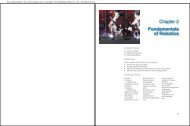
Thread Terms and Definitions<br />
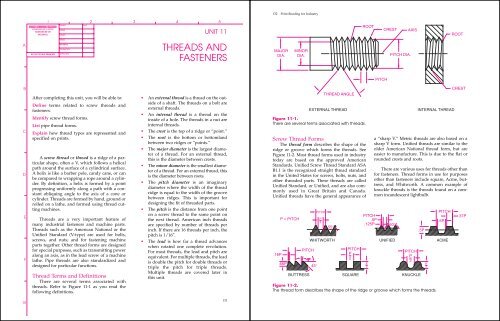
There are several terms associated with<br />
threads. Refer to Figure 11-1 as you read the<br />
following definitions.<br />
UNIT 11<br />
<strong>THREADS</strong> <strong>AND</strong><br />
<strong>FASTENERS</strong><br />
• An external thread is a thread on the outside<br />
of a shaft. The threads on a bolt are<br />
external threads.<br />
• An internal thread is a thread on the<br />
inside of a hole. The threads in a nut are<br />
internal threads.<br />
• The crest is the top of a ridge or “point.”<br />
• The root is the bottom or bottomland<br />
between two ridges or “points.”<br />
• The major diameter is the largest diameter<br />
of a thread. For an external thread,<br />
this is the diameter between crests.<br />
• The minor diameter is the smallest diameter<br />
of a thread. For an external thread, this<br />
is the diameter between roots.<br />
• The pitch diameter is an imaginary<br />
diameter where the width of the thread<br />
ridge is equal to the width of the groove<br />
between ridges. This is important for<br />
designing the fit of threaded parts.<br />
• The pitch is the distance from one point<br />
on a screw thread to the same point on<br />
the next thread. American inch threads<br />
are specified by number of threads per<br />
inch. If there are 16 threads per inch, the<br />
pitch is 1/16″.<br />
• The lead is how far a thread advances<br />
when rotated one complete revolution.<br />
For most threads, the lead and pitch are<br />
equivalent. For multiple threads, the lead<br />
is double the pitch for double threads or<br />
triple the pitch for triple threads.<br />
Multiple threads are covered later in<br />
this unit.<br />
131<br />
132 Print Reading for Industry<br />
MAJOR<br />
DIA.<br />
MINOR<br />
DIA.<br />
THREAD ANGLE<br />
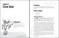
Screw Thread Forms<br />
The thread form describes the shape of the<br />
ridge or groove which forms the threads. See<br />
Figure 11-2. Most thread forms used in industry<br />
today are based on the approved American<br />
Standards. Unified Screw Thread Standard ASA<br />
B1.1 is the recognized straight thread standard<br />
in the United States for screws, bolts, nuts, and<br />
other threaded parts. These threads are called<br />
Unified Standard, or Unified, and are also commonly<br />
used in Great Britain and Canada.<br />
Unified threads have the general appearance of<br />
ROOT<br />
CREST AXIS<br />
PITCH DIA.<br />
EXTERNAL THREAD INTERNAL THREAD<br />
Figure 11-1.<br />
There are several terms associated with threads.<br />
.16P<br />
P = PITCH<br />
.66P<br />
PITCH<br />
PITCH<br />
P<br />
2<br />
55°<br />
PITCH<br />
ROOT<br />
CREST<br />
a “sharp V.” Metric threads are also based on a<br />
sharp V form. Unified threads are similar to the<br />
older American National thread form, but are<br />
easier to manufacture. This is due to the flat or<br />
rounded crests and roots.<br />
There are various uses for threads other than<br />
for fasteners. Thread forms in use for purposes<br />
other than fasteners include square, Acme, buttress,<br />
and Whitworth. A common example of<br />
knuckle threads is the threads found on a common<br />
incandescent lightbulb.<br />
PITCH<br />
.5P<br />
.125P 60°<br />
PITCH<br />
WHITWORTH UNIFIED ACME<br />
45°<br />
PITCH<br />
P<br />
2<br />
BUTTRESS SQUARE KNUCKLE<br />
P<br />
2<br />
PITCH<br />
P<br />
2<br />
Figure 11-2.<br />
The thread form describes the shape of the ridge or groove which forms the threads.<br />
.5P<br />
P<br />
2<br />
.5P<br />
.37P
Thread Representation<br />
A true projection view of a screw thread is<br />
not used due to the helical shape. Instead,<br />
threads are represented on a print in conventional<br />
ways. The three conventional methods in<br />
which threads may be represented on drawings<br />
are the detailed, schematic, and simplified methods.<br />
See Figure 11-3.<br />
The detailed convention most closely represents<br />
screw threads as they actually appear. This<br />
convention is sometimes used to show the<br />
geometry of a thread form as a portion of a<br />
greatly enlarged detail on a drawing. A rule of<br />
thumb is to draw detailed threads if the major<br />
diameter appears larger than 1″ on the drawing.<br />
The schematic convention and simplified<br />
convention are representations of the thread and<br />
are easier to draw. These conventions are recommended<br />
when the major diameter is less than 1″<br />
on the drawing. Both conventions are commonly<br />
used to save drafting time. The simplified<br />
convention is the easiest convention to use with<br />
most CAD systems.<br />
EXTERNAL <strong>THREADS</strong><br />
REGULAR VIEWS SECTION VIEWS<br />
DETAILED REPRESENTATION<br />
SCHEMATIC REPRESENTATION<br />
SIMPLIFIED REPRESENTATION<br />
Unit 11 Threads and Fasteners 133<br />
Thread Series<br />
There are four series of Unified screw<br />
threads—coarse, fine, extra fine, and constantpitch.<br />
See Figure 11-4 and Figure 11-5. Each<br />
series has its own designation. There are also<br />
three special thread series designated UNS, NS,<br />
and UN. These series cover special combinations<br />
of diameter, pitch, and length of engagement.<br />
The Unified coarse thread series is designated<br />
UNC. It is used for nuts, bolts, screws, and<br />
general uses where a fine thread is not required.<br />
The Unified fine thread series is designated<br />
UNF. It is used where the length of the threaded<br />
engagement is short and where a small lead<br />
angle is desired.<br />
The Unified extra fine series is designated<br />
UNEF. It is used for very short lengths of thread<br />
engagement and for thin-wall tubes, nuts, ferrules,<br />
and couplings.<br />
The Unified constant-pitch series is designated<br />
UN with the number of threads per inch<br />
INTERNAL <strong>THREADS</strong><br />
Figure 11-3.<br />
The three conventional methods for representing threads are detailed, schematic, and simplified.<br />
134 Print Reading for Industry<br />
NORMAL<br />
DIAMETER<br />
BASIC<br />
DIAMETER<br />
COARSE<br />
NC & UNC<br />
THDS<br />
PER<br />
IN<br />
TAP<br />
DRILL<br />
DIA<br />
FINE<br />
NF & UNF<br />
THDS<br />
PER<br />
IN<br />
TAP<br />
DRILL<br />
DIA<br />
EXTRA FINE<br />
NEF & UNEF<br />
THDS TAP<br />
PER DRILL<br />
IN DIA NORMAL<br />
0 .060 80 .0469<br />
1 .073 64 No.53 72 No.53<br />
2 .086 56 No.50 64 No.50<br />
3 .099 48 No.47 56 No.45<br />
4 .112 40 No.43 48 No.42<br />
5 .125 40 No.38 44 No.37<br />
6 .138 32 No.36 40 No.33<br />
8 .164 32 No.29 36 No.29<br />
10 .190 24 No.25 32 No.21<br />
12 .216 24 No.16 28 No.14 32 No.13<br />
1/4 .250 20 No.7 28 No.3 32 .2189<br />
5/16 .3125 18 F 24 I 32 .2813<br />
3/8 .375 16 .3125 24 Q 32 .3438<br />
7/16 .4375 14 U 20 .3906 28 .4062<br />
1/2 .500 13 .4219 20 .4531 28 .4688<br />
9/16 .5625 12 .4844 18 .5156 24 .5156<br />
5/8 .625 11 .5313 18 .5781 24 .5781<br />
11/16 .6875 ... ... ... ... 24 .6406<br />
3/4 .750 10 .6563 16 .6875 20 .7031<br />
13/16 .8125 ... ... ... ... 20 .7656<br />
7/8 .875 9 .7656 14 .8125 20 .8281<br />
15/16 .9375 ... ... ... ... 20 .8906<br />
Figure 11-4.<br />
Thread specifications for NC, UNC, NF, UNF, NEF, and UNEF threads.<br />
NORMAL<br />
DIAMETER<br />
8 PITCH<br />
8N & 8UN<br />
THDS<br />
PER<br />
IN<br />
TAP<br />
DRILL<br />
DIA<br />
12 PITCH<br />
12N & 12UNF<br />
THDS<br />
PER<br />
IN<br />
TAP<br />
DRILL<br />
DIA<br />
16 PITCH<br />
16N & 16UN<br />
THDS<br />
PER<br />
IN<br />
TAP<br />
DRILL<br />
.500 ... ... 12 .422 ... ...<br />
.563 ... ... 12 .484 ... ...<br />
.625 ... ... 12 .547 ... ...<br />
.688 ... ... 12 .609 ... ...<br />
.750 ... ... 12 .672 16 .688<br />
.813 ... ... 12 .734 16 .750<br />
.875 ... ... 12 .797 16 .813<br />
.934 ... ... 12 .869 16 .875<br />
1.000 8 .875 12 .922 16 .938<br />
1.063 ... ... 12 .984 16 1.000<br />
1.125 8 1.000 12 1.047 16 1.065<br />
1.188 ... ... 12 1.109 16 1.125<br />
1.250 8 1.125 12 1.72 16 1.188<br />
1.313 ... ... 12 1.234 16 1.250<br />
1.375 8 1.250 12 1.297 16 1.313<br />
1.434 ... ... 12 1.359 16 1.375<br />
1.500 8 1.375 12 1.422 16 1.438<br />
1.563 ... ... ... ... 16 1.500<br />
1.625 8 1.500 12 1.547 16 1.563<br />
1.688 ... ... ... ... 16 1.625<br />
1.750 8 1.625 12 1.672 16 1.688<br />
1.813 ... ... ... ... 16 1.750<br />
1.875 8 1.750 12 1.797 16 1.813<br />
1.934 ... ... ... ... 16 1.875<br />
2.000 8 1.875 12 1.922 16 1.938<br />
Figure 11-5.<br />
Thread specifications for constant pitch threads.<br />
DIA NORMAL<br />
DIAMETER<br />
BASIC<br />
DIAMETER<br />
COARSE<br />
NC & UNC<br />
THDS<br />
PER<br />
IN<br />
TAP<br />
DRILL<br />
DIA<br />
FINE<br />
NF & UNF<br />
THDS<br />
PER<br />
IN<br />
TAP<br />
DRILL<br />
DIA<br />
EXTRA FINE<br />
NEF & UNEF<br />
THDS<br />
PER<br />
IN<br />
TAP<br />
DRILL<br />
DIA<br />
1 1.000 8 .875 12 .922 20 .953<br />
1–1/16 1.063 ... ... ... ... 18 1.000<br />
1–1/8 1.125 7 .904 12 1.046 18 1.070<br />
1–3/16 1.188 ... ... ... ... 18 1.141<br />
1–1/4 1.250 7 1.109 12 1.172 18 1.188<br />
1–5/16 1.313 ... ... ... ... 18 1.266<br />
1–3/8 1.375 6 1.219 12 1.297 18 1.313<br />
1–7/16 1.438 ... ... ... ... 18 1.375<br />
1–1/2 1.500 6 1.344 12 1.422 18 1.438<br />
1–9/16 1.563 ... ... ... ... 18 1.500<br />
1–5/8 1.625 ... ... ... ... 18 1.563<br />
1–11/16 1.688 ... ... ... ... 18 1.625<br />
1–3/4 1.750 5 1.563 ... ... ... ...<br />
2 2.000 4.5 1.781 ... ... ... ...<br />
2–1/4 2.250 4.5 2.031 ... ... ... ...<br />
2–1/2 2.500 4 2.250 ... ... ... ...<br />
2–3/4 2.750 4 2.500 ... ... ... ...<br />
3 3.000 4 2.750 ... ... ... ...<br />
3–1/4 3.250 4 ... ... ... ... ...<br />
3–1/2 3.500 4 ... ... ... ... ...<br />
3–3/4 3.750 4 ... ... ... ... ...<br />
4 4.000 4 ... ... ... ... ...<br />
DIAMETER<br />
8 PITCH<br />
8N & 8UN<br />
THDS<br />
PER<br />
IN<br />
TAP<br />
DRILL<br />
DIA<br />
12 PITCH<br />
12N & 12UNF<br />
THDS<br />
PER<br />
IN<br />
TAP<br />
DRILL<br />
DIA<br />
16 PITCH<br />
16N & 16UN<br />
THDS<br />
PER<br />
IN<br />
TAP<br />
DRILL<br />
DIA<br />
2.063 ... ... ... ... 16 2.000<br />
2.125 ... ... 12 2.047 16 2.063<br />
2.188 ... ... ... ... 16 2.125<br />
2.250 8 2.125 12 2.172 16 2.188<br />
2.313 ... ... ... ... 16 2.250<br />
2.375 ... ... 12 2.297 16 2.313<br />
2.438 ... ... ... ... 16 2.375<br />
2.500 8 2.375 12 2.422 16 2.438<br />
2.625 ... ... 12 2.547 16 2.563<br />
2.750 8 2.625 12 2.717 16 2.688<br />
2.875 ... ... 12 ... 16 ...<br />
3.000 8 2.875 12 ... 16 ...<br />
3.125 ... ... 12 ... 16 ...<br />
3.250 8 ... 12 ... 16 ...<br />
3.375 ... ... 12 ... 16 ...<br />
3.500 8 ... 12 ... 16 ...<br />
3.625 ... ... 12 ... 16 ...<br />
3.750 8 ... ... ... 16 ...<br />
3.875 ... ... 12 ... 16 ...<br />
4.000 8 ... ... ... 16 ...<br />
4.250 8 ... 12 ... 16 ...<br />
4.500 8 ... ... ... 16 ...<br />
4.750 8 ... 12 ... 16 ...<br />
5.000 8 ... ... ... 16 ...<br />
5.250 8 ... 12 ... 16 ...
preceding the designation, such as 8UN. This series<br />
of threads is for special purposes, such as highpressure<br />
applications. Constant-pitch threads are<br />
also used for large diameters where the other<br />
thread series do not meet the requirements.<br />
Thread Classes<br />
After classification by form and series,<br />
threads are further classified by manufacturing<br />
tolerance. These classes are 1A, 2A, and 3A for<br />
external threads and 1B, 2B, and 3B for internal<br />
threads. On some older drawings, classes 2 and<br />
3 may appear without a letter designation.<br />
Classes 1A and 1B replace the older<br />
American Standard class 1. They are used in<br />
applications requiring minimum binding and<br />
allow for frequent and quick assembly or disassembly<br />
of parts.<br />
Classes 2A and 2B are threads with tighter<br />
tolerances. They are used for general purposes<br />
such as for nuts, bolts, screws, and normal applications<br />
by mass production industries.<br />
Class 3A and 3B are threads with very stringent<br />
and close tolerances. They are used for<br />
applications in industries requiring tighter tolerances<br />
than the preceding classes of 1A and 1B, or<br />
2A and 2B.<br />
Multiple Threads<br />
Threads can have two or three ridges running<br />
side-by-side. These are called double threads or<br />
triple threads. It may help to think of rope<br />
wrapped around a pole. If one rope is wrapped, it<br />
is like a single thread. If two ropes are wrapped,<br />
they are like double threads. Three ropes<br />
wrapped around the pole are like triple threads.<br />
Simply looking at the thread generally will<br />
not indicate if it is single, double, or triple.<br />
However, a close inspection should reveal a<br />
greater slope to double and triple threads than<br />
that found on single threads. Due to the greater<br />
slope angle of the thread, the “holding power”<br />
of a double or triple thread is less.<br />
Remember, the lead of a double thread is<br />
twice the pitch. One revolution of the threaded<br />
Unit 11 Threads and Fasteners 135<br />
cylinder advances two pitches because there are<br />
two ridges. Likewise, a triple thread advances<br />
three pitches.<br />
Left-Hand Threads<br />
Threads are most commonly created so that<br />
clockwise revolutions advance the threaded<br />
parts together. Common nuts and bolts tighten<br />
with clockwise turns. These threads are called<br />
right-hand threads. However, some applications<br />
require threads which tighten with counterclockwise<br />
movement. These threads are referred<br />
to as left-hand or reverse threads.<br />
Left-hand threads are usually found on<br />
items where right-hand threads may produce<br />
unwanted loosening, perhaps due to motion.<br />
Examples include bicycle pedal threads, threads<br />
on a flush handle, arbor nut on a table saw<br />
blade, and similar applications. Left-hand<br />
threads are indicated in a print using a callout.<br />
Detailed representations should also reflect a<br />
slope angle opposite that of right-hand threads.<br />
See Figure 11-6.<br />
CLOCKWISE<br />
RIGHT–H<strong>AND</strong> THREAD<br />
LEFT–H<strong>AND</strong> THREAD<br />
Figure 11-6.<br />
Right-hand and left-hand threads.<br />
COUNTERCLOCKWISE<br />
136 Print Reading for Industry<br />
Specification of Screw Threads<br />
A screw thread is specified on a drawing<br />
using a standard note with a leader and an<br />
arrow pointing to the thread. The note contains<br />
specific information for the specific thread. The<br />
note in Figure 11-7 is interpreted as follows.<br />
A) Nominal size (major diameter or screw<br />
number)<br />
B) Number of threads per inch<br />
C) Thread form<br />
D) Thread class number or symbol<br />
E) Left-hand (LH), double threads (DOUBLE)<br />
Threads are right-hand and single lead<br />
unless otherwise specified. The letters LH after<br />
the class symbol specify the thread as left hand.<br />
The word DOUBLE indicates double thread. The<br />
word TRIPLE indicates triple thread. Single<br />
threads and right-hand threads do not require<br />
RH or SINGLE to be specified.<br />
Schematic and simplified thread representations<br />
are not impacted by the thread form, the<br />
pitch, left-hand, or multiple thread status. The<br />
schematic spacing is usually just a factor of the<br />
major diameter, and nothing more.<br />
MAJOR DIAMETER IN INCHES<br />
NUMBER OF<br />
<strong>THREADS</strong> PER INCH<br />
THREAD<br />
FORM<br />
THREAD<br />
CLASS<br />
1/2 – 13 UNC 2A<br />
Figure 11-7.<br />
A screw thread is specified in a local note.<br />
Other specifications for threads may be<br />
given. These additional specifications may<br />
include thread length, hole size (for internal<br />
threads), or chamfer. See Figure 11-8.<br />
If the tolerance of the thread pitch diameter<br />
is given, it is placed at the end of the specification<br />
for the thread as follows.<br />
3<br />
− 10UNC − 2B PD 0.6850 TO 0.6927<br />
4<br />
The specification for a constant-pitch series<br />
thread with a tolerance for the pitch diameter<br />
would be listed as follows.<br />
1<br />
− 8UN − 3A PD 2.1688 TO 2.1611<br />
4 2<br />
Metric Threads<br />
Metric threads are graphically represented<br />
in the same manner as Unified and American<br />
National Standard. However, the format of the<br />
associated note is different. In a note for metric<br />
threads, the letter M is followed by the diameter<br />
and pitch. The M designates the thread as a<br />
metric series. Thread designation is for a<br />
coarse thread unless otherwise noted. Metric<br />
A B C D E<br />
1 – 5 ACME – 2A LH DOUBLE
17/32 – 1.25<br />
5/8 X 82°<br />
5/8 – 11UNC – 2B .75<br />
Figure 11-8.<br />
Additional specifications for a thread may<br />
include thread length, hole size, or chamfer.<br />
fine threads are designated by listing the pitch<br />
as a suffix.<br />
For example, in Figure 11-9, M8 is a coarse<br />
thread designation representing a nominal<br />
M8<br />
Figure 11-9.<br />
Metric threads are specified slightly different than other threads.<br />
Unit 11 Threads and Fasteners 137<br />
thread diameter of 8mm with a standardized<br />
pitch of 1.25mm understood. A fine thread designation<br />
for the part is M8×1.0. This indicates an<br />
8mm diameter with a pitch of 1.0mm. The most<br />
common metric thread is coarse. Metric coarse<br />
threads are generally between Unified coarse<br />
and fine series for a comparable diameter.<br />
The specification for metric series threads<br />
does not indicate the number of threads per unit<br />
of length, such as threads per millimeter. Instead,<br />
the pitch is indicated in the specification. For<br />
example, M8×1.0 designates the pitch is 1mm.<br />
The tolerance and class of fit for metric<br />
threads are designated by adding numbers and<br />
letters in a certain sequence to the callout. The<br />
thread designation in Figure 11-10 calls for a<br />
20mm diameter fine thread with a pitch of<br />
.75mm. In addition, the thread has a pitch diameter<br />
tolerance of grade 6 with an allowance “h”<br />
and a crest diameter tolerance grade 6 with an<br />
allowance “g.” See Unit 13 for a discussion of<br />
these tolerancing symbols.<br />
Pipe Threads<br />
The three forms of pipe threads used in<br />
industry are regular, aeronautical, and dryseal<br />
M8 X 1.0<br />
138 Print Reading for Industry<br />
METRIC THREAD<br />
DESIGNATION<br />
M20X1.5–6h6g<br />
MAJOR<br />
DIAMETER<br />
Figure 11-10.<br />
The tolerance class is added as a suffix to the thread note.<br />
pipe threads. The regular pipe thread is the standard<br />
for the plumbing trade. The aeronautical<br />
pipe thread is the standard in the aerospace<br />
industry. Regular and aeronautical pipe thread<br />
forms must be filled with a lute or sealer to prevent<br />
leakage in the joint. The dryseal pipe thread<br />
is the standard for automotive, refrigeration,<br />
and hydraulic tube/pipe fittings. Dryseal pipe<br />
threads do not allow leakage, even without the<br />
use of sealer. This is due to the metal-to-metal<br />
contact at the crest and root of the threads.<br />
Representation and Specification<br />
Straight and taper pipe threads are represented<br />
graphically in a similar manner as other<br />
screw threads. However, pipe threads are shown<br />
tapered at an angle of approximately 3° to the<br />
A B C D<br />
1/4 – 18 DRYSEAL NPTF<br />
Figure 11-11.<br />
Pipe threads are drawn similar to normal threads,<br />
but at a slight angle to the centerline axis.<br />
PITCH<br />
(FINE THREAD)<br />
PITCH DIAMETER TOLERANCE<br />
6 = GRADE<br />
g = POSITION (ALLOWANCE)<br />
CREST DIAMETER TOLERANCE<br />
6 = GRADE<br />
g = POSITION (ALLOWANCE)<br />
TOLERANCE CLASS<br />
centerline axis. See Figure 11-11.<br />
The specifications for American Standard<br />
Pipe Threads are listed in sequence of the nominal<br />
size, number of threads per inch, and the symbols<br />
for the thread series and form. For example,<br />
the thread specification 1/2-14NPT designates a<br />
1/2″ nominal size, 14 threads per inch, and an<br />
American Standard taper pipe thread.<br />
Pipe Thread Symbols<br />
The following symbols are used to designate<br />
American Standard pipe threads.<br />
• NPT. American Standard taper pipe<br />
thread.<br />
• NPTR. American Standard taper pipe<br />
thread for railing joints.<br />
• NPSC. American Standard pipe thread<br />
for couplings.<br />
• NPSM. American Standard pipe thread<br />
for free-fitting mechanical joints.<br />
• NPSL. American Standard pipe thread<br />
for loose-fitting mechanical joints with<br />
locknuts.<br />
• NPSH. American Standard pipe thread<br />
for hose couplings.<br />
Symbols for dryseal pipe threads are designated
as follows:<br />
• NPTF. Dryseal American Standard pipe<br />
thread.<br />
• PTF-SAE SHORT. Dryseal SAE short<br />
taper pipe thread.<br />
• NPSF. Dryseal American Standard fuel<br />
internal straight pipe thread.<br />
• NPSI. Dryseal American Standard intermediate<br />
internal straight pipe thread.<br />
A typical specification for dryseal pipe<br />
thread is shown in Figure 11-11. This specification<br />
includes:<br />
A) Nominal size<br />
B) Number of threads per inch<br />
C) Form (dryseal)<br />
D) Symbol<br />
Unit 11 Threads and Fasteners 139<br />
Print Reading Activities<br />
In the activities in this unit, you will read<br />
some actual industry prints. Many companies<br />
have their own drafting standards. As such, some<br />
items shown on industry prints may not exactly<br />
conform to the standards taught in this text.<br />
However, an important aspect of print reading is<br />
being able to correctly interpret all prints, including<br />
prints drawn to older or company-specific<br />
standards. Additional advanced print activities<br />
for this unit, APR11-1 and APR11-2, are located at<br />
the back of the book.<br />
140 Print Reading for Industry<br />
Print Reading Activity 11-1<br />
External Threads<br />
Refer to the print in PR11-1 and answer the<br />
following questions.<br />
1. What is the name of the part?<br />
2. What is the drawing number?<br />
3. As given in the title block, what is the<br />
scale of the drawing?<br />
4. What material is required?<br />
5. What is the maximum allowed finished<br />
length?<br />
6. What size is the hole drilled through<br />
the piece?<br />
7. Interpret the thread specification for A.<br />
.750<br />
10<br />
UNC<br />
2A<br />
8. Give the dimensions for the groove on<br />
the left-hand side of the part.<br />
9. Interpret the thread specification for B.<br />
1<br />
8<br />
UNC<br />
2A<br />
1.25 LG<br />
10. What does UNC stand for?<br />
1. ______________________________________<br />
2. ______________________________________<br />
3. ______________________________________<br />
4. ______________________________________<br />
5. ______________________________________<br />
6. ______________________________________<br />
7.<br />
______________________________________<br />
______________________________________<br />
______________________________________<br />
______________________________________<br />
8. ______________________________________<br />
9.<br />
______________________________________<br />
______________________________________<br />
______________________________________<br />
______________________________________<br />
______________________________________<br />
10. ______________________________________
B<br />
A<br />
PR11-1.<br />
Print supplied by Rockwell Manufacturing Company.<br />
Unit 11 Threads and Fasteners 141<br />
142 Print Reading for Industry<br />
A<br />
PR11-2.<br />
Print supplied by Johnson and Towers, Inc.
Print Reading Activity 11-2<br />
Internal Thread<br />
Refer to the print PR11-2 and answer the following<br />
questions.<br />
1. What is the name of the part?<br />
2. What is the number of the part?<br />
3. What material is specified?<br />
4. How many counterbored holes (C-BORE)<br />
are there on the part?<br />
5. What is the overall outside diameter of<br />
the part?<br />
6. How many threaded holes are there on<br />
this part?<br />
7. What is the diameter of the bolt circle<br />
that serves as a reference for the location<br />
of the threaded holes?<br />
8. What are the location dimensions for the<br />
hole at A?<br />
9. What is the size of the large center<br />
“through” hole?<br />
10. What type of thread representation is<br />
used in this drawing?<br />
Unit 11 Threads And Fasteners 143<br />
1. ______________________________________<br />
2. ______________________________________<br />
3. ______________________________________<br />
4. ______________________________________<br />
5. ______________________________________<br />
6. ______________________________________<br />
7. ______________________________________<br />
8. ______________________________________<br />
9. ______________________________________<br />
10. ______________________________________<br />
144 Print Reading for Industry<br />
Threads Activity 11-3<br />
Thread Interpretation<br />
For numbers 1–9, fill in the blanks for the<br />
sample threads shown in the drawings A–D. Use<br />
the colored lines as guidelines for lettering. Also,<br />
answer A, B, and C for number 10.<br />
1 1<br />
2 – 8 UNC – 2A<br />
FULL SCALE<br />
HALF SCALE<br />
A B C D<br />
.625 – 18UNF–2A LH TRIPLE<br />
LETTER THE INFORMATION FOR FIGURES A THROUGH D IN THE SPACES BELOW:<br />
A B C D<br />
1. NO <strong>THREADS</strong>/INCH<br />
2. PITCH OF THREAD<br />
3. THREAD FORM<br />
4. RH/LH?<br />
5. SINGLE OR WHICH?<br />
6. LEAD OF THREAD<br />
7. MAJOR DIAMETER<br />
8. INTERNAL/EXTERNAL?<br />
9. HOW REPRESENTED?<br />
M12 X 1.75<br />
10. FOR THE METRIC THREAD:<br />
A. WHAT IS THE MAJOR DIAMETER?<br />
B. WHAT IS THE PITCH?<br />
C. HOW IS IT REPRESENTED?