Wiring Diagram Book - Schneider Electric
Wiring Diagram Book - Schneider Electric
Wiring Diagram Book - Schneider Electric

You also want an ePaper? Increase the reach of your titles
YUMPU automatically turns print PDFs into web optimized ePapers that Google loves.
F<br />
U<br />
3<br />
F<br />
U<br />
1<br />
L1<br />
L2<br />
460 V<br />
F<br />
U 2<br />
L3<br />
H1 H3 H2 H4<br />
X1A<br />
A1 A2<br />
X1 115 V X2<br />
F<br />
U<br />
5<br />
R<br />
Power<br />
On<br />
Optional<br />
F<br />
U<br />
6<br />
X2A<br />
F<br />
U<br />
4<br />
FIBER OPTIC<br />
PUSH BUTTON,<br />
SELECTOR SWITCH,<br />
LIMIT SWITCH, ETC.<br />
OFF<br />
ON<br />
GND<br />
230 V<br />
H1 H3 H2 H4<br />
Optional Connection<br />
Electrostatically<br />
Shielded Transformer<br />
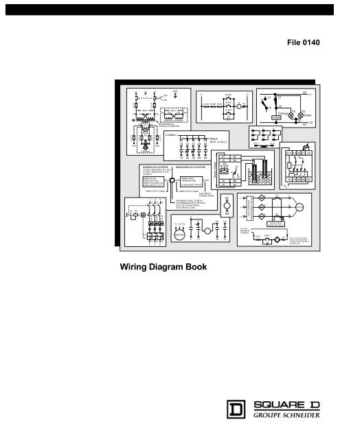
<strong>Wiring</strong> <strong>Diagram</strong> <strong>Book</strong><br />
Supply voltage<br />
HAZARDOUS LOCATIONS NONHAZARDOUS LOCATIONS<br />
CLASS I GROUPS A, B, C & D<br />
CLASS II GROUPS E, F & G<br />
CLASS III<br />
FIBER OPTIC CABLE<br />
1 3 5<br />
L1 L2 L3<br />
T1 T2 T3<br />
2 4 6<br />
Location<br />
13<br />
14<br />
FIBER OPTIC<br />
TRANSCEIVER<br />
CLASS 9005 TYPE FT<br />
L1<br />
A1 B1<br />
START<br />
L2<br />
15 B2<br />
B2<br />
START<br />
1B1<br />
STOP B3STOP STOP 2<br />
15<br />
M<br />
3<br />
OL<br />
16<br />
18<br />
FIBER OPTIC CABLE<br />
ELECTRICAL<br />
CONNECTIONS<br />
BOUNDARY SEAL TO BE IN<br />
ACCORDANCE WITH ARTICLE<br />
501-5 OF THE NATIONAL<br />
ELECTRICAL CODE<br />
T1 T2 T3<br />
MOTOR<br />
21 31 43 53<br />
22 32 44 54<br />
3<br />
2<br />
L1<br />
1<br />
T1<br />
16 18<br />
B3<br />
A2<br />
Status<br />
(N.O. or N.C.)<br />
Supply voltage<br />
L2<br />
T2<br />
L3<br />
T3<br />
START<br />
M<br />
L<br />
M<br />
A1 B1<br />
15<br />
B2<br />
B2<br />
B1 B3 15<br />
16<br />
18<br />
A1<br />
A2<br />
16 18<br />
B3<br />
A2<br />
2 Levels<br />
L1<br />
L2<br />
L3<br />
H<br />
CIRCUIT BREAKER<br />
OR DISCONNECT SWITCH<br />
TO 120 V<br />
SEPARATE<br />
CONTROL<br />
1<br />
5<br />
9<br />
13 (–)<br />
L<br />
M<br />
STOP<br />
2<br />
6<br />
10<br />
2 Levels<br />
H<br />
M<br />
M<br />
M<br />
SOLID STATE<br />
OVERLOAD RELAY<br />
START<br />
M<br />
13<br />
14<br />
1CT<br />
3CT<br />
M<br />
21<br />
22<br />
Orange<br />
LOAD<br />
4<br />
8<br />
12<br />
14 (+)<br />
V s<br />
OT*<br />
File 0140<br />
T1<br />
T2<br />
T3<br />
X3<br />
MOTOR<br />
AC L1<br />
X2<br />
Green<br />
X1<br />
L2<br />
AC<br />
A1/+ 15 25 Z1 Z2<br />
16 18 26 28 A2/–<br />
* OT is a switch that opens<br />
when an overtemperature<br />
condition exists (Type MFO<br />
and MGO only)
TRADEMARKS<br />
COPYRIGHT NOTICE<br />
PLEASE NOTE:<br />
QWIK-STOP®<br />
and ALHPA-PAK®<br />
are registered trademarks of Square D.<br />
®<br />
NEC is a registered trademark of the National Fire Protection Association.<br />
© 1993 Square D. All rights reserved. This document may not be copied in whole or in part, or transferred<br />
to any other media, without the written permission of Square D.<br />
<strong>Electric</strong>al equipment should be serviced only by qualified electrical maintenance personnel, and this<br />
document should not be viewed as sufficient instruction for those who are not otherwise qualified to<br />
operate, service or maintain the equipment discussed. Although reasonable care has been taken to provide<br />
accurate and authoritative information in this document, no responsibility is assumed by<br />
Square D for any consequences arising out of the use of this material.
Standard Elementary <strong>Diagram</strong> Symbols .....................1-3<br />
NEMA and IEC Markings and Schematic <strong>Diagram</strong>s...... 4<br />
Control and Power Connection Table 4<br />
Terminology...................................................................... 5<br />
Examples of Control Circuits .......................................... 6<br />
2-Wire Control 6<br />
3-Wire Control 6-9<br />
Shunting Thermal Units During Starting Period 10<br />
Overcurrent Protection for 3-Wire Control Circuits 11<br />
AC Manual Starters and Manual Motor<br />
Starting Switches ........................................................... 12<br />
Class 2510 12<br />
Class 2511 and 2512 13<br />
2-Speed AC Manual Starters and<br />
IEC Motor Protectors...................................................... 14<br />
Class 2512 and 2520 14<br />
GV1/GV3 14<br />
Drum Switches................................................................ 15<br />
Class 2601 15<br />
DC Starters, Constant and Adjustable Speed.............. 16<br />
Class 7135 and 7136 16<br />
Reversing DC Starters, Constant and<br />
Adjustable Speed ........................................................... 17<br />
Class 7145 and 7146 17<br />
Mechanically Latched Contactors ................................ 18<br />
Class 8196 18<br />
Medium Voltage Motor Controllers..........................18-25<br />
Class 8198 18-25<br />
Solid State Protective Relays...................................26-27<br />
Class 8430 26-27<br />
General Purpose Relays ................................................ 28<br />
Class 8501 28<br />
NEMA Control Relays..................................................... 29<br />
Class 8501 and 9999 29<br />
General Purpose Relays ................................................ 30<br />
Class 8501 30<br />
®<br />
Table of Contents<br />
Sensing Relays............................................................... 30<br />
RM2 LA1/LG1 30<br />
IEC Relays.................................................................. 31-32<br />
IEC D-Line Control Relays 31<br />
Class 8501 32<br />
Type P Contactors..................................................... 33-35<br />
Class 8502 33-35<br />
Class 8702 35<br />
Type T Overload Relays............................................ 33-35<br />
Class 9065 33-35<br />
Type S AC Magnetic Contactors.............................. 36-40<br />
Class 8502 36-40<br />
IEC Contactors .......................................................... 41-42<br />
IEC Contactors and Auxiliary Contact Blocks 41<br />
Input Modules and Reversing Contactors 42<br />
Type S AC Magnetic Starters ................................... 43-50<br />
Class 8536 43-50<br />
8538 and 8539 45,49<br />
1-Phase, Size 00 to 3 43<br />
2-Phase and 3-Phase, Size 00 to 5 44<br />
3-Phase, Size 6 45<br />
3-Phase, Size 7 46<br />
3-Phase Additions and Special Features 47-50<br />
Integral Self-Protected Starters ............................... 51-57<br />
Integral 18 State of Auxiliary Contacts 51-52<br />
Integral 32 and 63 State of Auxiliary Contacts 53-54<br />
<strong>Wiring</strong> <strong>Diagram</strong>s 55-57<br />
Type S AC Combination Magnetic Starters ............ 58-59<br />
Class 8538 and 8539 58-59<br />
3-Phase, Size 0-5 58<br />
3-Phase Additions and Special Features 59<br />
Reduced Voltage Controllers ................................... 60-66<br />
Class 8606 Autotransformer Type 60-61<br />
Class 8630 Wye-Delta Type 62-63<br />
Class 8640 2-Step Part-Winding Type 64<br />
Class 8647 Primary-Resistor Type 65<br />
Class 8650 and 8651 Wound-Rotor Type 66<br />
Solid State Reduced Voltage Starters .......................... 67<br />
®<br />
Class 8660 ALPHA PAK , Type MD-MG 67<br />
Solid State Reduced Voltage Controllers ............... 68-70<br />
Class 8660 Type MH, MJ, MK and MM 68-70<br />
i
Table of Contents<br />
Type S AC Reversing Magnetic Starters71-72<br />
Class 873671-72<br />
2- and 3-Pole71<br />
3- and 4-Pole72<br />
Type S AC 2-Speed Magnetic Starters73-76<br />
Class 881073-76<br />
Special Control Circuits75-76<br />
Multispeed Motor Connections76-77<br />
1- Phase76<br />
3-Phase76-77<br />
Programmable Lighting Controllers78<br />
Class 886578<br />
AC Lighting Contactors79-81<br />
Class 890379-81<br />
Load Connections79<br />
Control Circuit Connections80<br />
Panelboard Type <strong>Wiring</strong>81<br />
Electronic Motor Brakes81-82<br />
®<br />
Class 8922 QWIK-STOP 81-82<br />
Duplex Motor Controllers82<br />
Class 894182<br />
Fiber Optic Transceivers82<br />
Class 900582<br />
Photoelectric and Inductive Proximity Switches83<br />
Class 900683<br />
Photoelectric and Proximity Sensors84-89<br />
XS, XSC, XSF and XSD84<br />
XS and XTA85<br />
SG, ST and XUB86<br />
XUM, XUH, XUG, XUL and XUJ87<br />
XUE, XUR, XUD, XUG and XUE S88<br />
XUV89<br />
Limit Switches and Safety Interlocks90-92<br />
Class 900791<br />
XCK and MS92<br />
Pressure Switches and Transducers93<br />
Class 9012, 9013, 9022 and 902593<br />
Level Sensors and <strong>Electric</strong> Alternators94<br />
Class 9034 and 903994<br />
ii<br />
Pneumatic Timing Relays and Solid State<br />
Industrial Timing Relays95-96<br />
Class 905095-96<br />
Timers97<br />
Class 905097<br />
Transformer Disconnects98<br />
Class 907098<br />
Enclosure Selection Guide99<br />
Conductor Ampacity and Conduit Tables100-101<br />
Wire Data102<br />
<strong>Electric</strong>al Formulas103-104<br />
List of Tables<br />
Table 1 Standard Elementary <strong>Diagram</strong> Symbols 1<br />
Table 2 NEMA and IEC Terminal Markings 4<br />
Table 3 NEMA and IEC Controller Markings and<br />
Elementary <strong>Diagram</strong>s 4<br />
Table 4 Control and Power Connections for<br />
Across-the-Line Starters, 600 V or less4<br />
Table 5 Motor Lead Connections 64<br />
Table 6 Enclosures for Non-Hazardous Locations 99<br />
Table 7 Enclosures for Hazardous Locations 99<br />
Table 8 Conductor Ampacity100<br />
Table 9 Ampacity Correction Factors 101<br />
Table 10 Adjustment Factors 101<br />
Table 11 Ratings for 120/240 V, 3-Wire,<br />
Single-Phase Dwelling Services101<br />
Table 12 AWG and Metric Wire Data 102<br />
Table 13 <strong>Electric</strong>al Formulas for Amperes,<br />
Horsepower, Kilowatts and KVA 103<br />
Table 14 Ratings for 3-Phase, Single-Speed,<br />
Full-Voltage Magnetic Controllers<br />
for Nonplugglng and Nonjogging Duty 103<br />
Table 15 Ratings for 3-Phase, Single-Speed,<br />
Full-Voltage Magnetic Controllers for Plug-<br />
Stop, Plug-Reverse or Jogging Duty 104<br />
Table 16 Power Conversions 104<br />
®
Standard Elementary <strong>Diagram</strong> Symbols<br />
The diagram symbols in Table 1 are used by Square D and, where applicable, conform to NEMA (National <strong>Electric</strong>al Manufacturers Association)<br />
standards.<br />
Table 1 Standard Elementary <strong>Diagram</strong> Symbols<br />
Disconnect Circuit Interrupter Circuit Breakers<br />
w/ Thermal OL<br />
Pressure &<br />
Vacuum Switches<br />
Limit Switches<br />
N.O. N.C.<br />
Held Closed Held Open<br />
Flow Switches<br />
N.O. N.C.<br />
SWITCHES SELECTORS<br />
Foot Switches<br />
Circuit Breakers<br />
w/ Magnetic OL<br />
Liquid Level Switches Temperature<br />
Actuated Switches<br />
N.O. N.C. N.O. N.C. N.O. N.C.<br />
Speed (Plugging)<br />
F F<br />
R<br />
N.O. N.C.<br />
Anti-Plug<br />
PUSH BUTTONS – MOMENTARY CONTACT PUSH BUTTONS – MAINTAINED<br />
CONTACT<br />
N.O. N.C. N.O. & N.C.<br />
(double circuit)<br />
Non Push-to-Test<br />
A<br />
PILOT LIGHTS INSTANT OPERATING CONTACTS TIMED CONTACTS<br />
(indicate color by letter)<br />
Push-to-Test<br />
G<br />
Mushroom<br />
Head<br />
w/ Blowout<br />
N.O. N.C.<br />
Wobble<br />
Stick<br />
F<br />
R<br />
Illuminated<br />
R<br />
w/o Blowout<br />
N.O. N.C.<br />
2-Position Selector Switch<br />
J<br />
A1<br />
A2<br />
J<br />
A1<br />
A2<br />
K<br />
J K<br />
K<br />
J K<br />
A1<br />
A2<br />
3-Position Selector Switch<br />
L<br />
A1<br />
A2<br />
L<br />
2-Position Selector Push Button<br />
A B<br />
1 2<br />
3 4<br />
Selector Push Contacts<br />
Position Button 1-2 3-4<br />
A<br />
Free<br />
Depressed<br />
B<br />
Free<br />
Depressed<br />
2 Single<br />
Circuits<br />
= contact closed<br />
1 Double<br />
Circuit<br />
Contact action retarded after coil is:<br />
Energized<br />
Deenergized<br />
N.O.T.C. N.C.T.O. N.O.T.O. N.C.T.C.<br />
1
2<br />
Table 1 Standard Elementary <strong>Diagram</strong> Symbols (cont'd)<br />
INDUCTORS TRANSFORMERS<br />
Iron Core Air Core Auto Iron Core Air Core Current Dual Voltage<br />
OVERLOAD RELAYS AC MOTORS<br />
Thermal Magnetic Single Phase 3-Phase<br />
Squirrel Cage<br />
Armature Shunt Field<br />
(show 4 loops)<br />
DC MOTORS<br />
WIRING<br />
Series Field<br />
(show 3 loops)<br />
CAPACITORS RESISTORS<br />
SEMICONDUCTORS<br />
2-Phase, 4-Wire Wound Rotor<br />
Commutating or<br />
Compensating Field<br />
(show 2 loops)<br />
Not Connected Connected Power Control Terminal Ground Mechanical<br />
Connection<br />
Fixed Adjustable<br />
Fixed<br />
Diode or Half<br />
Wave Rectifier<br />
+<br />
DC<br />
Full Wave<br />
Rectifier<br />
AC<br />
AC<br />
DC<br />
Tunnel<br />
Diode<br />
NPN<br />
Transistor<br />
B<br />
Zener<br />
Diode<br />
C<br />
E<br />
RES<br />
B<br />
Bidirectional<br />
Breakdown Diode<br />
PNP<br />
Transistor<br />
C<br />
E<br />
Standard Elementary <strong>Diagram</strong> Symbols<br />
Heating<br />
Element<br />
E<br />
H<br />
Adjustable,<br />
by Fixed Taps<br />
RES<br />
Triac SCR PUT<br />
UJT,<br />
N Base<br />
B2<br />
B1<br />
E<br />
UJT,<br />
P Base<br />
B2<br />
B1<br />
Mechanical<br />
Interlock<br />
Connection<br />
Rheostat,<br />
Potentiometer or<br />
Adjustable Taps<br />
RES<br />
Photosensitive<br />
Cell<br />
Gate Turn-Of<br />
Thyristor<br />
G<br />
A<br />
K
Standard Elementary <strong>Diagram</strong> Symbols<br />
Table 1 Standard Elementary <strong>Diagram</strong> Symbols (cont'd)<br />
OTHER COMPONENTS<br />
Bell Annunciator<br />
Buzzer Horn, Alarm,<br />
Siren,etc.<br />
Battery<br />
+ –<br />
SPST: Single Pole, Single Throw<br />
SPDT: Single Pole, Double Throw<br />
DPST: Double Pole, Single Throw<br />
DPDT: Double Pole, Double Throw<br />
Fuse Thermocouple<br />
SUPPLEMENTARY CONTACT SYMBOLS<br />
IEC SYMBOLS<br />
STATIC SWITCHING CONTROL<br />
Static switching control is a method of switching electrical circuits without the use of contacts,<br />
primarily by solid state devices. To indicate static switching control, use the symbols shown in this<br />
table, enclosing them in a diamond as shown.<br />
N.O.:<br />
TERMS<br />
Normally Open<br />
N.C.: Normally Closed<br />
T.O.: Timed Open<br />
T.C.: Timed Closed<br />
Meter Shunt<br />
Meter (indicate<br />
type by letters)<br />
SPST, N.O.<br />
SPST, N.C.<br />
SPDT<br />
Single Break Double Break Single Break Double Break Single Break Double Break<br />
DPST, 2 N.O.<br />
DPST, 2 N.C.<br />
DPDT<br />
Single Break Double Break Single Break Double Break Single Break Double Break<br />
Limit Switch, N.O., Static Control<br />
Push Buttons Coil Aux. Contacts<br />
N.O. N.C.<br />
N.O. N.C.<br />
Contactor<br />
Breakers<br />
VM<br />
PUT: Programmable Unijunction Transistor<br />
SCR: Silicon Controlled Rectifier<br />
Triac: Bidirectional Triode Thyristor<br />
UJT: Unijunction Transistor<br />
3
4<br />
Table 2 NEMA and IEC Terminal Markings<br />
L1<br />
T1 T2 T3<br />
Alphanumeric, corresponding<br />
to incoming line and motor<br />
terminal designations<br />
NEMA<br />
Power Terminals Control Terminals Coil Terminals<br />
Table 3 NEMA and IEC Controller Markings and Elementary <strong>Diagram</strong>s<br />
IEC<br />
Power Terminals Control Terminals Coil Terminals<br />
NEMA<br />
Typical Controller Markings Typical Elementary <strong>Diagram</strong><br />
IEC<br />
Typical Controller Markings Typical Elementary <strong>Diagram</strong><br />
Table 4 Control and Power Connections for Across-the-Line Starters, 600 V or less<br />
(From NEMA standard ICS 2-321A.60)<br />
Line Markings<br />
Ground, when used<br />
1<br />
Motor Running<br />
Overcurrent,<br />
units in:<br />
L2<br />
L3<br />
2 4 6<br />
Single digit numeric,<br />
odd for supply lines,<br />
even for load connections<br />
A1<br />
A2<br />
1 element<br />
2 element<br />
3 element<br />
Control Circuit Connected to<br />
For Reversing, Interchange<br />
Lines<br />
3<br />
2<br />
3<br />
1<br />
2<br />
1/L1<br />
T1<br />
5<br />
3<br />
4<br />
5<br />
6<br />
L2<br />
T2<br />
13<br />
14<br />
L3<br />
T3<br />
21<br />
22<br />
1-Phase 2-Phase, 4-Wire 3-Phase<br />
L1, L2<br />
L1, L3: Phase 1<br />
L2, L4: Phase 2<br />
L1, L2, L3<br />
L1 is always ungrounded — L2<br />
L1<br />
—<br />
—<br />
NEMA and IEC Markings and Schematic <strong>Diagram</strong>s<br />
Control and Power Connection Table<br />
No specific<br />
marking<br />
14 22<br />
2-digit numeric, 1st<br />
designates sequence,<br />
2nd designates function<br />
(1-2 for N.C., 3-4 for N.O.)<br />
—<br />
L1, L4<br />
—<br />
No standard<br />
designation<br />
—<br />
—<br />
L1, L2, L3<br />
L1, L2 L1, L3 L1, L2<br />
A1<br />
A2<br />
One<br />
Winding<br />
— L1, L3 L1, L3<br />
A1<br />
A2 A3<br />
Tapped<br />
Winding<br />
A1 A3 A1 B1<br />
A2<br />
Tapped<br />
Winding<br />
L1 L2<br />
START M<br />
STOP<br />
OL<br />
1 2 3<br />
11 STOP 12 23 START 24 A1 A2 95 96<br />
23 24<br />
A2 B2<br />
Two<br />
Windings
Terminology<br />
A wiring diagram shows, as closely as possible, the actual<br />
location of all component parts of the device. The open<br />
terminals (marked by an open circle) and arrows represent<br />
connections made by the user.<br />
Since wiring connections and terminal markings are<br />
shown, this type of diagram is helpful when wiring the<br />
device or tracing wires when troubleshooting. Bold lines<br />
denote the power circuit and thin lines are used to show the<br />
control circuit. Black wires are conventionally used in<br />
power circuits and red wire in control circuits for AC<br />
magnetic equipment.<br />
A wiring diagram is limited in its ability to completely convey<br />
the controller’s sequence of operation. The elementary<br />
diagram is used where an illustration of the circuit in its<br />
simplest form is desired.<br />
An elementary diagram is a simplified circuit illustration.<br />
Devices and components are not shown in their actual<br />
positions. All control circuit components are shown as<br />
directly as possible, between a pair of vertical lines<br />
representing the control power supply. Components are<br />
arranged to show the sequence of operation of the devices<br />
and how the device operates. The effect of operating<br />
various auxiliary contacts and control devices can be<br />
readily seen. This helps in troubleshooting, particularly with<br />
the more complex controllers.<br />
This form of electrical diagram is sometimes referred to as<br />
a “schematic” or “line” diagram.<br />
WIRING DIAGRAM<br />
ELEMENTARY DIAGRAM<br />
5
Examples of Control Circuits<br />
2- and 3-Wire Control<br />
Elementary <strong>Diagram</strong>s<br />
6<br />
Low Voltage Release and Low Voltage Protection are the basic control circuits encountered in motor control applications. The simplest schemes<br />
are shown below. Other variations shown in this section may appear more complicated, but can always be resolved into these two basic<br />
schemes.<br />
Note: The control circuits shown in this section may not include overcurrent protective devices required by applicable electrical codes. See page<br />
11 for examples of control circuit overcurrent protective devices and their use.<br />
Low Voltage Release:<br />
2-Wire Control<br />
FIG. 1<br />
L1 L2<br />
FIG. 2<br />
1<br />
3<br />
Low voltage release is a 2-wire control scheme using a<br />
maintained contact pilot device in series with the starter coil.<br />
This scheme is used when a starter is required to function<br />
automatically without the attention of an operator. If a power<br />
failure occurs while the contacts of the pilot device are closed,<br />
the starter will drop out. When power is restored, the starter<br />
will automatically pickup through the closed contacts of the<br />
pilot device.<br />
The term “2-wire” control is derived from the fact that in the<br />
basic circuit, only two wires are required to connect the pilot<br />
device to the starter.<br />
2-Wire Control:<br />
Maintained Contact Hand-OFF-Auto Selector Switch<br />
A Hand-Off-Auto selector switch is used on 2-wire control<br />
applications where it is desirable to operate the starter manually<br />
as well as automatically. The starter coil is manually energized<br />
when the switch is turned to the Hand position and is<br />
automatically energized by the pilot device when the switch is<br />
in the Auto position.<br />
M<br />
PILOT DEVICE SUCH AS<br />
LIMIT SWITCH,<br />
PRESSURE SWITCH, ETC.<br />
FIG. 3<br />
L1 L2<br />
FIG. 4<br />
A1 I<br />
A2<br />
I<br />
HAND OFF AUTO<br />
A1 3A<br />
M OL<br />
1A<br />
2A<br />
A2<br />
2-WIRE CONTROL DEVICE<br />
Low Voltage Protection:<br />
3-Wire Control<br />
L1 L2<br />
OL<br />
START M<br />
1 STOP 2 3<br />
M<br />
Low voltage protection is a 3-wire control scheme using<br />
momentary contact push buttons or similar pilot devices to<br />
energize the starter coil.<br />
This scheme is designed to prevent the unexpected starting of<br />
motors, which could result in injury to machine operators or<br />
damage to the driven machinery. The starter is energized by<br />
pressing the Start button. An auxiliary holding circuit contact on<br />
the starter forms a parallel circuit around the Start button<br />
contacts, holding the starter in after the button is released. If a<br />
power failure occurs, the starter will drop out and will open the<br />
holding circuit contact. When power is restored, the Start button<br />
must be operated again before the motor will restart.<br />
The term “3-wire” control is derived from the fact that in the<br />
basic circuit, at least three wires are required to connect the<br />
pilot devices to the starter.<br />
3-Wire Control:<br />
Momentary Contact Multiple Push Button Station<br />
When a motor must be started and stopped from more than one<br />
location, any number of Start and Stop push buttons may be<br />
wired together. It is also possible to use only one Start-Stop<br />
station and have several Stop buttons at different locations to<br />
serve as an emergency stop.<br />
OL<br />
L1 START<br />
L2<br />
1<br />
STOP STOP STOP<br />
START<br />
2<br />
START<br />
M<br />
3<br />
M<br />
OL
3-Wire Control:<br />
Pilot Light Indicates when Motor is Running<br />
FIG. 1 FIG. 2<br />
L1 L2<br />
1<br />
A pilot light can be wired in parallel with the starter coil to<br />
indicate when the starter is energized, indicating the motor is<br />
running.<br />
3-Wire Control:<br />
Push-to-Test Pilot Light Indicates when Motor is<br />
Running<br />
FIG. 3<br />
L1 L2<br />
FIG. 4<br />
1<br />
STOP<br />
2<br />
START 3<br />
When the Motor Running pilot light is not lit, there may be doubt<br />
as to whether the circuit is open or whether the pilot light bulb<br />
is burned out. To test the bulb, push the color cap of the Pushto-Test<br />
pilot light.<br />
3-Wire Control:<br />
Fused Control Circuit Transformer<br />
FIG. 5 L1<br />
L2 FIG. 6<br />
FU1 FU2<br />
STOP<br />
STOP<br />
2<br />
As an operator safety precaution, a step-down transformer can<br />
be used to provide a control circuit voltage lower than line<br />
voltage. The diagram above shows one way to provide<br />
overcurrent protection for control circuits.<br />
M<br />
START 3<br />
START<br />
M<br />
M<br />
TEST<br />
M<br />
R<br />
M<br />
M<br />
OL<br />
OL<br />
R<br />
OL<br />
GROUND<br />
(If used)<br />
3-Wire Control:<br />
Pilot Light Indicates when Motor is Stopped<br />
L1 L2<br />
1<br />
STOP<br />
M<br />
2<br />
START 3<br />
M<br />
A pilot light may be required to indicate when the motor is<br />
stopped. This can be implemented by wiring a normally-closed<br />
auxiliary contact on the starter in series with the pilot light, as<br />
shown above. When the starter is deenergized, the pilot light<br />
illuminates. When the starter picks up, the auxiliary contact<br />
opens, turning off the light.<br />
3-Wire Control:<br />
Illuminated Push Button Indicates when Motor is<br />
Running<br />
The illuminated push button combines a Start button and pilot<br />
light in one unit. Pressing the pilot light lens operates the Start<br />
contacts. Space is saved by using a two-unit push button<br />
station instead of three.<br />
3-Wire Control:<br />
Fused Control Circuit Transformer and Control Relay<br />
L1<br />
A starter coil with a high VA rating may require a control transformer<br />
of considerable size. A control relay and a transformer with a low<br />
VA rating can be connected so the normally-open relay contact<br />
controls the starter coil on the primary or line side. Square D Size 5<br />
Combination Starter Form F4T starters use this scheme.<br />
M<br />
OL<br />
L1 L2<br />
1 STOP 2<br />
START*<br />
3<br />
M OL<br />
STOP<br />
Examples of Control Circuits<br />
3-Wire Control<br />
Elementary <strong>Diagram</strong>s<br />
M<br />
R *<br />
* Pushing on pilot light operates Start contacts.<br />
CR<br />
START<br />
M<br />
M<br />
CR<br />
G<br />
OL<br />
GROUND<br />
(If used)<br />
L2<br />
7
Examples of Control Circuits<br />
3-Wire Control<br />
Elementary <strong>Diagram</strong>s<br />
8<br />
Jogging: Selector Switch and Start Push Button Jogging: Selector Push Button<br />
FIG. 1 FIG. 2<br />
Jogging, or inching, is defined by NEMA as the momentary<br />
operation of a motor from rest for the purpose of accomplishing<br />
small movements of the driven machine. One method of jogging<br />
is shown above. The selector switch disconnects the holding<br />
circuit contact and jogging may be accomplished by pressing the<br />
Start push button.<br />
A selector push button may be used to obtain jogging, as shown<br />
above. In the Run position, the selector-push button provides<br />
normal 3-wire control. In the Jog position, the holding circuit is<br />
broken and jogging is accomplished by depressing the<br />
push button.<br />
Jogging: Control Relay Jogging: Control Relay for Reversing Starter<br />
FIG. 3 FIG. 4<br />
When the Start push button is pressed, the control relay is<br />
energized, which in turn energizes the starter coil. The normallyopen<br />
starter auxiliary contact and relay contact then form a<br />
holding circuit around the Start push button. When the Jog push<br />
button is pressed, the starter coil is energized (independent of the<br />
relay) and no holding circuit forms, thus jogging can be obtained.<br />
3-Wire Control:<br />
More than 1 Starter, 1 Push Button Station Controls all<br />
FIG. 5 FIG. 6<br />
FPO 7-5<br />
FPO 7-1<br />
When one Start-Stop station is required to control more than one<br />
starter, the scheme above can be used. A maintained overload on<br />
any one of the motors will drop out all three starters.<br />
This control scheme permits jogging the motor either in the<br />
forward or reverse direction, whether the motor is at standstill or<br />
rotating. Pressing the Start-Forward or Start-Reverse push button<br />
energizes the corresponding starter coil, which closes the circuit<br />
to the control relay.The relay picks up and completes the holding<br />
circuit around the Start button. As long as the relay is energized,<br />
either the forward or reverse contactor remains energized.<br />
Pressing either Jog push button will deenergize the relay,<br />
releasing the closed contactor. Further pressing of the Jog button<br />
permits jogging in the desired direction.<br />
3-Wire Control:<br />
Reversing Starter<br />
FPO 7-2<br />
FPO 7-3 FPO 7-4<br />
FPO 7-6<br />
3-wire control of a reversing starter can be implemented with a<br />
Forward-Reverse-Stop push button station as shown above. Limit<br />
switches may be added to stop the motor at a certain point in either<br />
direction. Jumpers 6 to 3 and 7 to 5 must then be removed.
3-Wire Control:<br />
Reversing Starter Multiple Push Button Station<br />
FIG. 1 FIG. 2<br />
More than one Forward-Reverse-Stop push button station may be<br />
required and can be connected in the manner shown above.<br />
3-Wire Control:<br />
2-Speed Starter<br />
FIG. 3 FIG. 4<br />
3-wire control of a 2-speed starter with a High-Low-Stop push button<br />
station is shown above. This scheme allows the operator to start the<br />
motor from rest at either speed or to change from low to high speed.<br />
The Stop button must be operated before it is possible to change from<br />
high to low speed. This arrangement is intended to prevent excessive<br />
line current and shock to motor and driven machinery, which results<br />
when motors running at high speed are reconnected for a lower speed.<br />
Plugging:<br />
Plugging a Motor to a Stop from 1 Direction Only<br />
FIG. 5 FIG. 6<br />
Plugging is defined by NEMA as a braking system in which the motor<br />
connections are reversed so the motor develops a counter torque, thus<br />
exerting a retarding force. In the above scheme, forward rotation of the<br />
motor closes the normally-open plugging switch contact and<br />
energizing control relay CR. When the Stop push button is operated,<br />
the forward contactor drops out, the reverse contactor is energized<br />
through the plugging switch, control relay contact and normally-closed<br />
forward auxiliary contact. This reverses the motor connections and the<br />
motor is braked to a stop. The plugging switch then opens and<br />
disconnects the reverse contactor. The control relay also drops out.<br />
The control relay makes it impossible for the motor to be plugged in<br />
reverse by rotating the motor rotor closing the plugging switch. This<br />
type of control is not used for running in reverse.<br />
Examples of Control Circuits<br />
3-Wire Control<br />
Elementary <strong>Diagram</strong>s<br />
3-Wire Control: Reversing Starter w/ Pilot Lights to<br />
Indicate Motor Direction<br />
Pilot lights may be connected in parallel with the forward and<br />
reverse contactor coils, indicating which contactor is energized<br />
and thus which direction the motor is running.<br />
3-Wire Control: 2-Speed Starter w/ 1 Pilot Light to<br />
Indicate Motor Operation at Each Speed<br />
One pilot light may be used to indicate operation at both low and<br />
high speeds. One extra normally-open auxiliary contact on each<br />
contactor is required. Two pilot lights, one for each speed, may<br />
be used by connecting pilot lights in parallel with high and low<br />
coils (see reversing starter diagram above).<br />
Anti-Plugging:<br />
Motor to be Reversed but Must Not be Plugged<br />
Anti-plugging protection is defined by NEMA as the effect of a<br />
device that operates to prevent application of counter-torque by<br />
the motor until the motor speed has been reduced to an<br />
acceptable value. In the scheme above, with the motor operating<br />
in one direction, a contact on the anti-plugging switch opens the<br />
control circuit of the contactor used for the opposite direction.<br />
This contact will not close until the motor has slowed down, after<br />
which the other contactor can be energized.<br />
9
Examples of Control Circuits<br />
Shunting Thermal Units During Starting Period<br />
Elementary <strong>Diagram</strong>s<br />
10<br />
Shunting Thermal Units During Starting Period<br />
Article 430-35 of the NEC describes circumstances under<br />
which it is acceptable to shunt thermal units during<br />
abnormally long accelerating periods.<br />
430-35. Shunting During Starting Period.<br />
(a) Nonautomatically Started. For a nonautomatically<br />
started motor, the overload protection shall be<br />
permitted to be shunted or cut out of the circuit during<br />
the starting period of the motor if the device by which<br />
the overload protection is shunted or cut out cannot be<br />
left in the starting position and if fuses or inverse time<br />
circuit breakers rated or set at not over 400 percent of<br />
the full-load current of the motor are so located in the<br />
circuit as to be operative during the starting period of<br />
the motor.<br />
(b) Automatically Started. The motor overload protection<br />
shall not be shunted or cut out during the starting<br />
period if the motor is automatically started.<br />
Exception. The motor overload protection shall be<br />
permitted to be shunted or cut out during the starting period<br />
on an automatically started motor where:<br />
(1) The motor starting period exceeds the time delay<br />
of available motor overload protective devices, and<br />
(2) Listed means are provided to:<br />
a. Sense motor rotation and to automatically<br />
prevent the shunting or cut out in the event<br />
that the motor fails to start, and<br />
b. Limit the time of overload protection shunting<br />
or cut out to less than the locked rotor time<br />
rating of the protected motor, and<br />
c. Provide for shutdown and manual restart if<br />
motor running condition is not reached.<br />
Figures 1 and 2 show possible circuits for use in<br />
conjunction with 3-wire control schemes. Figure 1 complies<br />
with NEC requirements. Figure 2 exceeds NEC<br />
requirements, but the additional safety provided by the zero<br />
speed switch might be desirable.<br />
Figure 3 shows a circuit for use with a 2-wire, automatically<br />
started control scheme that complies with NEC<br />
requirements. UL or other listed devices must be used in<br />
this arrangement.<br />
FIG. 1<br />
FIG. 2<br />
FIG. 3<br />
FPO 9-1<br />
FPO 9-2<br />
FPO 9-3
3-Wire Control:<br />
Fusing in 1 Line Only<br />
FIG. 1<br />
L1<br />
L2<br />
FIG. 2<br />
FU1<br />
STOP<br />
Common control with fusing in one line only and with both lines<br />
ungrounded or, if user’s conditions permit, with one line grounded.<br />
3-Wire Control:<br />
Fusing in Both Primary Lines<br />
FIG. 3 L1<br />
L2<br />
FIG. 4<br />
FU1<br />
STOP<br />
Control circuit transformer with fusing in both primary lines, no<br />
secondary fusing and all lines ungrounded.<br />
3-Wire Control:<br />
Fusing in Both Primary Lines and 1 Secondary Line<br />
FIG. 5 L1<br />
L2<br />
FIG. 6<br />
FU1 FU2<br />
PRI<br />
STOP<br />
FU3<br />
START<br />
Control circuit transformer with fusing in one secondary line and<br />
both primary lines, with one line grounded.<br />
M<br />
PRI<br />
SEC<br />
X1 X2<br />
START<br />
M<br />
SEC<br />
START<br />
M<br />
M<br />
M<br />
M<br />
OL<br />
GND<br />
FU2<br />
OL<br />
OL<br />
GND<br />
Examples of Control Circuits<br />
Overcurrent Protection for 3-Wire Control Circuits<br />
Elementary <strong>Diagram</strong>s<br />
L1<br />
FU1<br />
3-Wire Control:<br />
Fusing in Both Lines<br />
STOP<br />
START<br />
Common control with fusing in both lines and with both lines<br />
ungrounded.<br />
3-Wire Control:<br />
Fusing in Both Primary and Secondary Lines<br />
L1<br />
FU3<br />
STOP<br />
Control circuit transformer with fusing in both primary lines and<br />
both secondary lines, with all lines ungrounded.<br />
3-Wire Control:<br />
Fusing in Both Primary and Secondary Lines<br />
For Large Starters using Small Transformer<br />
L1<br />
FU3<br />
STOP<br />
Control circuit transformer with fusing in both primary lines and<br />
both secondary lines, with all lines ungrounded. Used for large VA<br />
coils only.<br />
M<br />
PRI<br />
START<br />
M<br />
M<br />
FU1 FU2<br />
SEC<br />
X1 X2<br />
CR<br />
PRI<br />
START<br />
M<br />
M<br />
M<br />
FU1 FU2<br />
SEC<br />
X1 X2<br />
CR<br />
FU2<br />
OL<br />
FU4<br />
OL<br />
FU4<br />
OL<br />
L2<br />
L2<br />
L2<br />
11
AC Manual Starters and Manual Motor Starting Switches<br />
Class 2510<br />
12<br />
Manual Motor Starting Switches:<br />
Class 2510 Type K<br />
FIG. 1 T1 L1<br />
FIG. 2<br />
L1<br />
T3 L3<br />
T1 T3<br />
MOTOR<br />
2-Pole, 1-Phase 3-Pole, 3-Phase<br />
Fractional Horsepower Manual Starters:<br />
Class 2510 Type F<br />
FIG. 3 T2<br />
FIG. 4 T2<br />
FIG. 5<br />
L2<br />
L2<br />
T1<br />
T1 T2<br />
MOTOR<br />
R<br />
L1<br />
PILOT<br />
LIGHT<br />
(IF USED)<br />
R<br />
L2<br />
PILOT<br />
LIGHT<br />
(IF USED)<br />
1-Pole 2-Pole 2-Pole w/ Selector Switch<br />
Integral Horsepower Manual Starters:<br />
Class 2510 Size M0 and M1<br />
FIG. 6 L1<br />
L2 FIG. 7 L1 L2 T2 FIG. 8<br />
L1 L2<br />
FIG. 9 L1 L2 L3 FIG. 10<br />
T1<br />
T1 T2<br />
MOTOR<br />
T2<br />
T1<br />
T1 T2<br />
MOTOR<br />
T1<br />
T1 T2<br />
MOTOR<br />
T1<br />
L1<br />
R<br />
L2<br />
T2<br />
L1<br />
T1 T3<br />
MOTOR<br />
PILOT<br />
LIGHT<br />
(IF USED)<br />
2-Pole, 1-Phase 3-Pole, DC 3-Pole, 1-Phase 3-Pole, 3-Phase 3-Pole, 3-Phase w/ additional<br />
Interlock (Form X)<br />
L3<br />
T3<br />
T1<br />
T2<br />
T3<br />
R<br />
T1 T2 T3<br />
MOTOR<br />
T1<br />
L1<br />
L2<br />
L3<br />
A O H<br />
2 1<br />
A<br />
O<br />
H<br />
4 3<br />
T2<br />
T1 T2 T3<br />
MOTOR<br />
PILOT<br />
LIGHT<br />
(IF USED)<br />
T3<br />
T2<br />
T1<br />
2 4<br />
2-WIRE<br />
CONTROL<br />
DEVICE<br />
R<br />
L2<br />
L1<br />
PILOT<br />
LIGHT<br />
(IF USED)<br />
4 T2<br />
MOTOR<br />
L1<br />
T1<br />
L2<br />
T2<br />
T1 T2 T3<br />
MOTOR<br />
L3<br />
T3<br />
®
®<br />
AC Manual Starters and Manual Motor Starting Switches<br />
Class 2511 and 2512<br />
AC Reversing Manual Starters and Manual Motor Starting Switches:<br />
Class 2511<br />
FIG. 1 FWD REV<br />
FIG. 2<br />
T1 L1<br />
T2 L2<br />
T3 L3<br />
T1 T2 T3<br />
MOTOR<br />
Reversing Manual Motor Starting Switch<br />
Type K, 3-Pole, 3-Phase<br />
Reversing Manual Starter<br />
Sizes M0 and M1, 3-Pole, 3-Phase<br />
AC 2-Speed Manual Motor Starting Switches:<br />
Class 2512 Type K<br />
FIG. 3 FIG. 4<br />
2-Pole, 1-Phase w/ Pilot Lights 3-Pole, 3-Phase<br />
AC 2-Speed Manual Motor Starters:<br />
Class 2512 Type F<br />
FIG. 5 FIG. 6<br />
FPO<br />
13-1a<br />
FPO<br />
12-6a<br />
2-Unit, 2-Pole w/ Mechanical Interlock and Pilot Lights 3-Unit, 2-Pole w/ Selector Switch and Pilot Lights<br />
L1<br />
T1<br />
L2<br />
T2<br />
L3<br />
T3<br />
T1 T2 T3<br />
MOTOR<br />
FPO<br />
12-6b<br />
FPO 13-1b<br />
13
2-Speed AC Manual Starters and IEC Motor Protectors<br />
Class 2512 and 2520 and Telemecanique GV1/GV3<br />
14<br />
FIG. 1<br />
2-Speed AC Manual Motor Starters:<br />
Class 2512 Size M0 and M1<br />
2-Speed Manual Starter for Wye-Connected, Separate Winding Motor<br />
Motor Protective Switches:<br />
Class 2520<br />
FIG. 2 1/L1 3/L2 5/L3 FIG. 3 1/L1 3/L2 5/L3 FIG. 4<br />
3-Pole, 3-Phase 2-Pole Application 1-Pole Application<br />
IEC Manual Starters:<br />
GV1/GV3<br />
FIG. 5<br />
1/L1 3/L2 5/L3<br />
FIG. 6 FIG. 7<br />
FIG. 8<br />
2/T1<br />
4/T2<br />
T1 T2 T3<br />
MOTOR<br />
T2 T11 T13<br />
T1 T3 T12<br />
6/T3<br />
MOTOR<br />
I> I> I><br />
2/T1 4/T2 6/T3<br />
GV3 M• Motor Protector<br />
GV3 A08 GV3 A09<br />
95<br />
97<br />
I> I><br />
96<br />
98<br />
2/T1<br />
GV3 A0• Fault Signalling Contacts GV3 Voltage Trips GV1 A0• Contact Block<br />
T1<br />
L1<br />
4/T2<br />
T2<br />
T1 T3<br />
MOTOR<br />
L2<br />
GV3 B•<br />
D1<br />
D2<br />
6/T3<br />
<<br />
GV3 D•<br />
C1<br />
C2<br />
T3<br />
L3<br />
T11 T12 T13<br />
1/L1<br />
2/T1<br />
T3<br />
3/L2<br />
4/T2<br />
MOTOR<br />
5/L3<br />
6/T3<br />
GV1 A01 GV1 A02<br />
13 21 13 23<br />
14 22 14 24<br />
GV1 A03 GV1 A05<br />
13 23 31 13 23 33<br />
14 24 32 14 24 34<br />
GV1 A06 GV1 A07<br />
13 23 33 13 23 31<br />
14 24 34 14 24 33<br />
®
Drum Switches:<br />
Class 2601<br />
FIG. 1 HANDLE END<br />
FIG. 2 MOTOR DRUM SW. LINE FIG. 3<br />
REVERSE OFF FORWARD<br />
1 2<br />
3 4<br />
5 6<br />
®<br />
1 2<br />
3 4<br />
5 6<br />
1 2<br />
3 4<br />
5 6<br />
Drum Switches<br />
Class 2601<br />
Internal Switching 3-Phase, 3-Wire Motor 1-Phase, Capacitor or Split-Phase Motor<br />
FIG. 4 MOTOR DRUM SW. LINE FIG. 5<br />
MOTOR DRUM SW.<br />
1-Phase, 4-Lead Repulsion Induction Motor 1-Phase, 3-Lead Repulsion Induction Motor<br />
FIG. 6 MOTOR DRUM SW. LINE<br />
FIG. 7<br />
2-Phase, 3-Wire Motor 2-Phase, 4-Wire Motor<br />
FIG. 8<br />
MOTOR DRUM SW.<br />
FIG. 9 MOTOR DRUM SW. LINE FIG. 10<br />
1 2<br />
LINE<br />
1 2<br />
ARMATURE<br />
SHUNT FIELD<br />
ARMATURE<br />
3<br />
4<br />
5 6<br />
1<br />
3<br />
5<br />
1<br />
3<br />
5<br />
2<br />
4<br />
6<br />
2<br />
4<br />
6<br />
COMMON<br />
SERIES<br />
FIELD<br />
3<br />
DC, Shunt Motor DC, Series Motor DC, Compound Motor<br />
1<br />
3<br />
2<br />
4<br />
5 6<br />
4<br />
5 6<br />
RUN<br />
MOTOR DRUM SW.<br />
1<br />
3<br />
5<br />
2<br />
4<br />
6<br />
MOTOR DRUM SW.<br />
SHUNT FIELD<br />
1<br />
3<br />
2<br />
4<br />
5 6<br />
START<br />
1<br />
3<br />
2<br />
4<br />
5 6<br />
LINE<br />
LINE<br />
MOTOR DRUM SW.<br />
SERIES<br />
FIELD<br />
1 2<br />
ARMATURE<br />
3<br />
4<br />
5 6<br />
LINE<br />
LINE<br />
15
DC Starters, Constant and Adjustable Speed<br />
Class 7135 and 7136<br />
16<br />
FIG. 1<br />
FIG. 2<br />
FPO 15-1<br />
Typical Elementary <strong>Diagram</strong> for<br />
NEMA Size 2, 3 and 4<br />
FPO 15-2<br />
Typical Elementary <strong>Diagram</strong> for<br />
NEMA Size 2, 3 and 4<br />
Constant Speed DC Starter: Class 7135<br />
Adjustable Speed DC Starter: Class 7136<br />
Acceleration Contactors: Class 7135, 7136, 7145 and 7146<br />
NEMA Size 1 2 3 4 5<br />
No. of Acceleration Contactors 1 2 2 2 3<br />
®
®<br />
FIG. 1<br />
FIG. 2<br />
Reversing DC Starters, Constant and Adjustable Speed<br />
Class 7145 and 7146<br />
Reversing Constant Speed DC Starter: Class 7145<br />
FPO 16-1<br />
Typical Elementary <strong>Diagram</strong><br />
for NEMA Size 2, 3 and 4<br />
Reversing Adjustable Speed DC Starter: Class 7146<br />
FPO 16-2<br />
Typical Elementary <strong>Diagram</strong><br />
for NEMA Size 2, 3 and 4<br />
17
Mechanically Latched Contactors and Medium Voltage Motor Controllers<br />
Class 8196 and 8198<br />
18<br />
FIG. 1<br />
FIG. 2<br />
Mechanically Latched Contactor:<br />
Class 8196 Type FL13, FL23, FL12 and FL22<br />
FPO 17-2<br />
150%<br />
Full-Voltage, Non-Reversing Squirrel Cage Motor Controller:<br />
Class 8198 Type FC11, FC21, FC13, FC23, FC12 and FC22<br />
FPO 17-1<br />
145%<br />
®
FIG. 1<br />
®<br />
Full-Voltage Squirrel Cage Motor Controller:<br />
Class 8198 Type FCR1 and FCR2<br />
Medium Voltage Motor Controllers<br />
Class 8198<br />
FPO 17-3<br />
160%<br />
19
Medium Voltage Motor Controllers<br />
Class 8198<br />
20<br />
FIG. 1<br />
Reduced-Voltage, Primary Reactor, Non-Reversing Squirrel Cage Motor Controller:<br />
Class 8198 Type RCR1 and RCR2<br />
FPO 18-1<br />
130%<br />
®
FIG. 1<br />
®<br />
Medium Voltage Motor Controllers<br />
Class 8198<br />
Reduced-Voltage, Primary Reactor, Autotransformer, Non-Reversing Squirrel Cage Motor Controller:<br />
Class 8198 Type RCA1 and RCA2<br />
FPO 18-2<br />
150%<br />
21
Medium Voltage Motor Controllers<br />
Class 8198<br />
22<br />
FIG. 1<br />
Full Voltage, Non-Reversing Synchronous Motor Controller:<br />
Class 8198 Type FS1 and FS2<br />
FPO 19-1<br />
170%<br />
®
FIG. 1<br />
®<br />
Medium Voltage Motor Controllers<br />
Class 8198<br />
Reduced-Voltage, Primary Reactor, Non-Reversing Synchronous Motor Controller:<br />
Class 8198 Type RS1 and RS2<br />
FPO 19-2<br />
140%<br />
23
Medium Voltage Motor Controllers<br />
Class 8198<br />
24<br />
FIG. 1<br />
Reduced-Voltage, Autotransformer, Non-Reversing Synchronous Motor Controller:<br />
Class 8198 Type RSA1 and RSA2<br />
FPO 20-1<br />
160%<br />
®
FIG. 1<br />
®<br />
Full-Voltage, Non-Reversing, Brushless Synchronous Motor Controller:<br />
Class 8198 Type FSB1 and FSB2<br />
Medium Voltage Motor Controllers<br />
Class 8198<br />
FPO 20-2<br />
155%<br />
25
Solid State Protective Relays<br />
Class 8430<br />
26<br />
FIG. 1<br />
FIG. 2<br />
L1<br />
L2<br />
L3<br />
STOP<br />
12<br />
14<br />
22<br />
24<br />
Solid State Protective Relays:<br />
Class 8430 Type DAS, DASW, DASV and DASVW<br />
M OL<br />
M OL<br />
M OL<br />
START<br />
Solid State Protective Relays:<br />
Class 8430<br />
FIG. 3 FIG. 4 FIG. 5<br />
V S<br />
Dashed lines<br />
represent<br />
optional contacts<br />
STOP<br />
L1<br />
L2<br />
L3<br />
START<br />
M<br />
Dashed lines represent<br />
optional contacts<br />
A1 11 21 B1 B2<br />
12 14 22 24 A2<br />
12<br />
14<br />
22<br />
24<br />
Input<br />
Signal<br />
Dashed lines represent optional contacts<br />
(DIAW and DUAW devices only)<br />
L1<br />
L2<br />
L3<br />
11<br />
21<br />
FIG. 6<br />
Type MPS 240V<br />
Type DIA, DIAW, DUA and DUAW Type MPD Type MPS 480V<br />
M<br />
L1<br />
L2<br />
L3<br />
11<br />
21<br />
T1<br />
T2<br />
T3<br />
MOTOR<br />
M<br />
M<br />
1 2 3 4 5 6<br />
7 8 9 10 11 12<br />
OL<br />
With the line voltage connections directly at<br />
the motor terminals, the relay will detect all<br />
phase loss conditions ahead of the connection<br />
points. However, the motor may sustain a<br />
momentary “bump” in the reverse condition if<br />
the proper phase sequence is not present.<br />
M OL<br />
M OL<br />
M OL<br />
OL<br />
L1<br />
L2<br />
L3<br />
T1<br />
T2<br />
T3<br />
MOTOR<br />
With the line voltage connections<br />
ahead of the starter, the motor can<br />
be started in the reverse direction.<br />
The relay cannot detect a phase loss<br />
on the load side of the starter.<br />
4 5<br />
3 6<br />
2<br />
1<br />
8<br />
7<br />
1 2 3<br />
4 5 6<br />
7 8 9<br />
A B<br />
L1<br />
L2<br />
L3<br />
L3<br />
L2<br />
L1<br />
®
®<br />
FIG. 1<br />
FIG. 2<br />
Load Detector Relay:<br />
Class 8430 Type V<br />
FPO 22-1<br />
<strong>Wiring</strong> <strong>Diagram</strong><br />
Elementary <strong>Diagram</strong> (Common Control)<br />
Load Converter Relay:<br />
Class 8430 Type G<br />
FPO 22-2<br />
Solid State Protective Relays<br />
Class 8430<br />
FPO 22-3<br />
27
General Purpose Relays<br />
Class 8501<br />
28<br />
Control Relays:<br />
Class 8501 Type CO and CDO<br />
FIG. 1 FIG. 2 FIG. 3 FIG. 4 FIG. 5 FIG. 6<br />
Type CO6 and<br />
CDO6<br />
Type CO7 and<br />
CDO7<br />
Type CO8 and<br />
CDO8<br />
FIG. 7<br />
Type CO21 and<br />
CDO21<br />
Control Relays:<br />
Class 8501 Type UBS<br />
Control Relays:<br />
Class 8501 Type K<br />
Type CO15 and<br />
CDO15<br />
FIG. 8 1<br />
3<br />
FIG. 9 FIG. 10<br />
4<br />
7<br />
A<br />
COMMON LATCH<br />
Type KL Type KU, KF, KX, KUD, KFD and KXD<br />
2-Pole<br />
FIG. 11 FIG. 12 FIG. 13<br />
1<br />
4<br />
7<br />
A<br />
–<br />
+<br />
6<br />
9<br />
3<br />
6<br />
9<br />
LATCH<br />
RESET<br />
8<br />
RESET<br />
B<br />
B<br />
+<br />
–<br />
L1<br />
STOP<br />
START<br />
Type KLD Type KU, KF, KX, KUD, KFD and KXD<br />
3-Pole<br />
9<br />
1<br />
4<br />
7<br />
1<br />
4<br />
7<br />
A<br />
M<br />
M<br />
L2<br />
10 8 5<br />
TERMINAL NUMBERS<br />
2<br />
5<br />
8<br />
3<br />
6<br />
9<br />
3<br />
6<br />
9<br />
B<br />
A B<br />
2<br />
Type CO16, CDO16, CO22 and<br />
CDO22<br />
2<br />
3<br />
1<br />
4 5<br />
Type KP and KPD<br />
2-Pole<br />
4<br />
3<br />
Type KP and KPD<br />
3-Pole<br />
8<br />
6<br />
6<br />
5 7<br />
1 11<br />
7<br />
8<br />
10<br />
9<br />
®
FIG. 1<br />
FIG. 2<br />
®<br />
10 A Control Relay w/ Convertible Contacts:<br />
Class 8501 Type X<br />
FPO 27-1<br />
* Note: Class 8501 Type XO••••XL, XDO••••XL, XDO••••XDL and<br />
XO••••XDL latch relays use the same diagram except for the<br />
addition of an unlatch coil (8 poles maximum).<br />
TIMED CONTACTS<br />
POLE #13<br />
POLE #14<br />
Note: All contacts are<br />
convertible.<br />
14<br />
13<br />
14<br />
13<br />
2 N.O.<br />
Timer Attachment:<br />
Class 9999 Type XTD and XTE<br />
1 N.C. 1 N.O.<br />
14<br />
13<br />
14<br />
13<br />
14<br />
13<br />
14<br />
13<br />
2 N.C.<br />
ON<br />
DELAY<br />
(TDE)<br />
OFF<br />
DELAY<br />
(TDD)<br />
NEMA Control Relays<br />
Class 8501 and 9999<br />
No. of<br />
Timed<br />
Contacts<br />
Class<br />
9999<br />
Type<br />
2<br />
XTD<br />
XTE<br />
* O = N.O. Contact<br />
1 = N.C. Contact<br />
Pole No.*<br />
13 14<br />
O 1<br />
29
General Purpose Relays and Sensing Relays<br />
Class 8501 and Telemecanique RM2 LA1/LG1<br />
30<br />
FIG. 1 FIG. 2<br />
1<br />
Miniature Control Relays:<br />
Class 8501 Type RS and RSD<br />
Type RS41 and RSD41 Type RS42 and RSD42<br />
FIG. 3 FIG. 4<br />
1 2 4<br />
Type RS43 and RSD43 Type RS4, RSD4, RS14, RSD14, RS24, RSD24,<br />
RS34, RSD34, RS44 and RSD44<br />
Control Relays w/ Intrinsically Safe Terminals:<br />
Class 8501 Type TO41 and TO43<br />
FIG. 5 FIG. 6<br />
1 ON 2 3 4 5 6<br />
OFF<br />
FIG. 7<br />
Supply voltage<br />
5<br />
9<br />
13 (–)<br />
5<br />
9<br />
13 (–)<br />
6<br />
10<br />
14 (+)<br />
8<br />
12<br />
14 (+)<br />
Intrinsically Safe Terminals Non-Hazardous Location Terminals<br />
A1 B1<br />
15 B2<br />
B2<br />
B1 B3 15<br />
OFF ON<br />
1<br />
5<br />
9<br />
7<br />
Sensing Relays:<br />
RM2 LA1/LG1<br />
B1<br />
B2<br />
13 (–)<br />
2<br />
6<br />
10<br />
13 (–)<br />
1<br />
5<br />
9<br />
4<br />
8<br />
12<br />
3<br />
7<br />
11<br />
14 (+)<br />
14 (+)<br />
4<br />
8<br />
12<br />
SUPPLY<br />
VOLTAGE<br />
8 9 10 11 12<br />
Supply voltage<br />
A1 15<br />
B2<br />
B1 B3<br />
B3 B1 B2<br />
16 18<br />
H<br />
H<br />
16 18<br />
16 B3<br />
L<br />
M<br />
18 A2<br />
M<br />
16 18 X X A2<br />
2 Levels 1 Level<br />
RM2 LG1 RM2 LA1<br />
15<br />
M<br />
H<br />
L<br />
H = High level<br />
electrode<br />
L = Low level<br />
electrode<br />
M = Reference<br />
electrode<br />
(common)<br />
®
®<br />
Control Relays: CA2 and CA3<br />
FIG. 1 FIG. 2 FIG. 3<br />
4 N.O. Instantaneous<br />
CA2 DN40 and CA3 DN40<br />
3 N.O. & 1 N.C. Instantaneous<br />
CA2 DN31 and CA3 DN31<br />
FIG. 4 FIG. 5<br />
2 N.O. & 2 N.C. Instantaneous, w/ 2 Make-Before-Break<br />
CA2 DC22 and CA3 DC22<br />
2 N.O. & 2 N.C. Instantaneous<br />
CA2 DN22 and CA3 DN22<br />
2 N.O. & 2 N.C. Instantaneous w/ Mechanical Latch<br />
CA2 DK22 and CA3 DK22<br />
Front-Mounted Standard Instantaneous Auxiliary Contact Blocks: LA1<br />
FIG. 6 FIG. 7 FIG. 8 FIG. 9 FIG. 10<br />
1 N.O. & 1 N.C.<br />
LA1 DN11<br />
2 N.O.<br />
LA1 DN20<br />
2 N.C.<br />
LA1 DN02<br />
2 N.O. & 2 N.C.<br />
LA1 DN22<br />
FIG. 11 FIG. 12 FIG. 13 FIG. 14<br />
2 N.O. & 2 N.C. w/ 2 Make-Before-Break<br />
LA1 DC22<br />
4 N.O.<br />
LA1 DN40<br />
4 N.C.<br />
LA1 DN04<br />
1 N.O. & 3 N.C.<br />
LA1 DN13<br />
3 N.O. & 1 N.C.<br />
LA1 DN31<br />
Front-Mounted Damp- and Dust-Protected Instantaneous Auxiliary Contact Blocks: LA1<br />
FIG. 15 FIG. 16 FIG. 17 FIG. 18<br />
53<br />
NO<br />
2 N.O.<br />
LA1 DX20<br />
53 61<br />
NO NC<br />
54 62<br />
A1<br />
A2<br />
53<br />
NO<br />
63<br />
NO<br />
54 64<br />
13 23 33 43<br />
NO NO NO NO<br />
14 24 34 44<br />
61<br />
NC<br />
75<br />
NC<br />
A1<br />
13 21 35 47<br />
NO NC NC NO<br />
A2 14 22 36 48<br />
87<br />
NO<br />
54 62 76 88<br />
53 63<br />
NO NO<br />
54 64<br />
2 N.O. w/ Grounding Screw<br />
LA1 DY20<br />
2 Dusttight N.O. & 2 N.O.<br />
LA1 DZ40<br />
Front-Mounted Time Delay Auxiliary Contacts: LA2 and LA3<br />
FIG. 19 FIG. 20 FIG. 21<br />
On Delay, 1 N.O. & 1 N.C.<br />
LA2 DT<br />
On Delay, 1 N.C. w/ 1 Offset N.O.<br />
LA2 DS<br />
2 Dusttight N.O. & 1 N.O. & 1 N.C.<br />
LA1 DZ31<br />
Off Delay, 1 N.O. & 1 N.C.<br />
LA3 DR<br />
Front-Mounted Mechanical Latch Adder Blocks: LA6 Side-Mounted Auxiliary Contact Blocks: LA8<br />
FIG. 22 FIG. 23 FIG. 24 FIG. 25<br />
A1<br />
A2<br />
E1<br />
E2<br />
55 67<br />
NC NO<br />
56 68<br />
53<br />
NO<br />
63<br />
NO<br />
54 64<br />
A2<br />
A1<br />
45<br />
46<br />
LA6 DK1 LA6 DK2 1 N.O. & 1 N.C. Instantaneous<br />
LA8 DN11<br />
A1<br />
13 21 33 43<br />
NO NC NO NO<br />
A2 14 22 34 44<br />
51 61<br />
NC NC<br />
52 62<br />
53 63 73 83<br />
NO NO NO NO<br />
54 64 74 84<br />
E1<br />
E2<br />
55 67<br />
NC NO<br />
56 68<br />
E1<br />
E2<br />
53<br />
NO<br />
53 63 73 83<br />
NO NO NO NO<br />
54 64 74 84<br />
61<br />
NC<br />
71<br />
NC<br />
A1<br />
A1<br />
13 21<br />
NO NC<br />
31 43<br />
NC NO<br />
A2 14 22 32 44<br />
13 21<br />
NO NC<br />
31<br />
NC<br />
43<br />
NO<br />
A2 14 22 32 44<br />
83<br />
NO<br />
54 62 72 84<br />
51 61 71 81<br />
NC NC NC NC<br />
52 62 72 82<br />
53/ 84<br />
NO<br />
54/ 83NO<br />
61/<br />
NC<br />
62/ 71NC<br />
IEC Relays<br />
IEC D-Line Control Relays<br />
(for input modules see page 42)<br />
72<br />
57<br />
NO<br />
65<br />
NC<br />
58 66<br />
53 61<br />
NO NC<br />
53<br />
NO<br />
71 81<br />
NC NC<br />
54 62 72 82<br />
53 61<br />
NO NC<br />
73 83<br />
NO NO<br />
54 62 74 84<br />
61<br />
NC<br />
73<br />
NO<br />
83<br />
NO<br />
54 62 74 84<br />
53/ 84<br />
NO<br />
54/ 83NO<br />
63/<br />
NO<br />
74<br />
2 N.O. Instantaneous<br />
LA8 DN20<br />
64/ 73NO<br />
31
IEC Relays<br />
Class 8501<br />
32<br />
FIG. 3<br />
Miniature IEC Relays:<br />
Class 8501 Type PR 1<br />
FIG. 1 13 21<br />
FIG. 2<br />
A1 NO NC<br />
A1<br />
A2<br />
PR 1.11 E<br />
PR 1.20 E<br />
A2 14 22<br />
A1<br />
A2<br />
13 23<br />
NO NO<br />
14 24<br />
PRD 1.11 E<br />
PRD 1.20 E<br />
Type PR 1 and PRD 1 Relays Type PV Adder Decks for PR 1.20 E<br />
13<br />
14<br />
23<br />
24<br />
Alternating Relays:<br />
Class 8501 Type PHA<br />
relay coil<br />
13 14<br />
energized<br />
deenergized<br />
closed<br />
open<br />
23 24 closed<br />
open<br />
33 41<br />
NO NC<br />
34 42<br />
31 41<br />
NC NC<br />
32 42<br />
PV 02<br />
33 43<br />
NO NO<br />
PV 11 PV 20<br />
34 44<br />
®
®<br />
Power Terminals Coil Terminals<br />
FIG. 1 FIG. 2<br />
1 3 5<br />
Power terminals on contactors, overloads and switches are single<br />
digits – odd for line side terminals and even for load side terminals.<br />
Coil terminals are designated by a letter and a number. Terminals<br />
for a single winding coil are designated “A1” and “A2”.<br />
Auxiliary Contact Terminals Overload Relay Contact Terminals<br />
FIG. 3<br />
Location<br />
FIG. 4<br />
95<br />
13 21 31 43 53<br />
Status<br />
(N.O. or N.C.)<br />
Auxiliary contacts on contactors, relays and push button contacts<br />
use 2-digit terminal designations, as shown in the diagram above.<br />
The first digit indicates the location of the contact on the device. The<br />
second digit indicates the status of the contacts, N.O. or N.C. “1”<br />
and “2” indicate N.C. contacts. “3” and “4” indicate N.O. contacts.<br />
FIG. 5<br />
14<br />
2<br />
22<br />
32<br />
FPO 30-2 120%<br />
4<br />
44<br />
6<br />
54<br />
Type P Contactors and Type T Overload Relays<br />
Class 8502 and 9065<br />
Class 8502 Type PD or PE Contactor<br />
w/ Class 9065 Type TR Overload Relay<br />
<strong>Wiring</strong> <strong>Diagram</strong><br />
FPO 30-2 120%<br />
Elementary <strong>Diagram</strong><br />
97<br />
96 98<br />
With Isolated<br />
N.O. Alarm Contact<br />
Overload contact terminals are marked with two digits. The first<br />
digit is “9”. The second digits are “5” and “6” for a N.C. and “7” and<br />
“8” for a N.O. isolated contact. If the device has a non-isolated<br />
alarm contact (single pole), the second digits of the N.O. terminals<br />
are “5” and “8”.<br />
A1<br />
A2<br />
95<br />
96 98<br />
With Non-Isolated<br />
N.O. Alarm Contact<br />
33
Type P Contactors and Type T Overload Relays<br />
Class 8502 and 9065<br />
34<br />
FIG. 1<br />
FIG. 2<br />
FIG. 3<br />
FPO 30-3 120%<br />
FPO 30-4 120%<br />
FPO 31-1 120%<br />
Class 8502 Type PG or PD Contactor<br />
w/ Class 9065 Type TD Overload Relay<br />
<strong>Wiring</strong> <strong>Diagram</strong> Elementary <strong>Diagram</strong><br />
Class 8502 Type PE Contactor<br />
w/ Class 9065 Type TE Overload Relay<br />
<strong>Wiring</strong> <strong>Diagram</strong> Elementary <strong>Diagram</strong><br />
Class 8502 Type PF, PG or PJ Contactor<br />
w/ Class 9065 Type TF, TG or TJ Overload Relay<br />
FPO 30-3 120%<br />
FPO 30-4 120%<br />
FPO 31-1 120%<br />
<strong>Wiring</strong> <strong>Diagram</strong> Elementary <strong>Diagram</strong><br />
®
FIG. 4<br />
FIG. 1<br />
FPO 31-2 120%<br />
®<br />
Type P Reversing Contactors and Type T Overload Relays<br />
Class 8502, 8702 and 9065<br />
Class 8502 Type PJ or PK Contactor<br />
w/ Class 9065 Type TJE Overload Relay<br />
<strong>Wiring</strong> <strong>Diagram</strong> Elementary <strong>Diagram</strong><br />
Class 8702 Type PDV or PEV Reversing Contactor<br />
w/ Class 9065 Type TR Overload Relay<br />
FPO 31-3<br />
Elementary <strong>Diagram</strong><br />
FPO 31-3 120%<br />
Elementary <strong>Diagram</strong><br />
FPO 31-2 120%<br />
35
Type S AC Magnetic Contactors<br />
Class 8502<br />
36<br />
AC Magnetic Contactors:<br />
Class 8502 Type S<br />
FIG. 1<br />
3<br />
L1 L2<br />
FIG. 2<br />
1<br />
T1 L2<br />
MOTOR<br />
2<br />
1-Pole, Size 0 and 1 2-Pole, Size 00, 0 and 1<br />
FIG. 3 3<br />
FIG. 4<br />
T1 T2<br />
MOTOR<br />
2-Pole, Size 2 to 5 3-Pole, Size 00 to 5<br />
FIG. 5<br />
3<br />
FIG. 6<br />
T1 T3 T4 T2<br />
MOTOR<br />
2<br />
2<br />
L1<br />
1<br />
T1<br />
L1<br />
1<br />
4-Pole, Size 0, 1 and 2 5-Pole, Size 0, 1 and 2<br />
FIG. 7 FIG. 8<br />
T1<br />
T1<br />
L3<br />
T3<br />
L2<br />
T2<br />
L4<br />
T4<br />
L2<br />
T2<br />
T1 T2 T3<br />
MOTOR<br />
T1 T2<br />
MOTOR<br />
T1 T2 T3<br />
MOTOR<br />
2- and 3-Wire Control for Figure 1 to 5 Separate Control for Figure 6<br />
3<br />
2<br />
3<br />
2<br />
L1<br />
T1<br />
3<br />
2<br />
L1<br />
1<br />
TO<br />
SEPARATE<br />
CONTROL<br />
T1<br />
X2<br />
L1<br />
1<br />
L2<br />
T2<br />
T1<br />
3<br />
X2<br />
L2<br />
T2<br />
L3<br />
T3<br />
L2<br />
T2<br />
L3<br />
T3<br />
®
FIG. 1<br />
®<br />
Size 6, 3-Pole Contactor – Common Control<br />
Class 8502 Type SH Series B<br />
<strong>Wiring</strong> <strong>Diagram</strong><br />
Elementary <strong>Diagram</strong><br />
Type S AC Magnetic Contactors<br />
Class 8502<br />
This symbol denotes the coil function,<br />
provided by a solid-state control module,<br />
30 VA transformer, two fuses in the<br />
secondary of the transformer, N.C.<br />
electrical interlock and DC magnet coil.<br />
Short-Circuit Protection<br />
Rating of branch circuit protective device must<br />
comply with applicable electrical codes and the<br />
following limitations:<br />
Type of Device Max. Rating<br />
Class K5 or RK5 time-delay fuse 600 A<br />
Class J, T or L fuse 1200 A<br />
Inverse-time circuit breaker 800 A<br />
37
Type S AC Magnetic Contactors<br />
Class 8502<br />
38<br />
FIG. 1<br />
Size 6, 3-Pole Contactor – Separate Control<br />
Class 8502 Type SH Form S Series B<br />
<strong>Wiring</strong> <strong>Diagram</strong><br />
Elementary <strong>Diagram</strong><br />
This symbol denotes the coil function,<br />
provided by a solid-state control module,<br />
30 VA transformer, two fuses in the<br />
secondary of the transformer, N.C.<br />
electrical interlock and DC magnet coil.<br />
Short-Circuit Protection<br />
Rating of branch circuit protective device must<br />
comply with applicable electrical codes and the<br />
following limitations:<br />
Type of Device Max. Rating<br />
Class K5 or RK5 time-delay fuse 600 A<br />
Class J, T or L fuse 1200 A<br />
Inverse-time circuit breaker 800 A<br />
®
FIG. 1<br />
®<br />
Size 7, 3-Pole Contactor – Common Control<br />
Class 8502 Type SJ Series A<br />
<strong>Wiring</strong> <strong>Diagram</strong><br />
Elementary <strong>Diagram</strong><br />
Type S AC Magnetic Contactors<br />
Class 8502<br />
This symbol denotes the coil function,<br />
provided by a solid-state control module,<br />
30 VA transformer, two fuses in the<br />
secondary of the transformer, N.C.<br />
electrical interlock and DC magnet coil.<br />
Short-Circuit Protection<br />
Rating of branch circuit protective device must<br />
comply with applicable electrical codes and the<br />
following limitations:<br />
Type of Device Max. Rating<br />
Class K5 or RK5 time-delay fuse 600 A<br />
Class J, T or L fuse 1600 A<br />
Inverse-time circuit breaker 2000 A<br />
39
Type S AC Magnetic Contactors<br />
Class 8502<br />
40<br />
FIG. 1<br />
Size 7, 3-Pole Contactor – Separate Control<br />
Class 8502 Type SJ Form S Series A<br />
<strong>Wiring</strong> <strong>Diagram</strong><br />
Elementary <strong>Diagram</strong><br />
This symbol denotes the coil function,<br />
provided by a solid-state control module,<br />
30 VA transformer, two fuses in the<br />
secondary of the transformer, N.C.<br />
electrical interlock and DC magnet coil.<br />
Short-Circuit Protection<br />
Rating of branch circuit protective device must<br />
comply with applicable electrical codes and the<br />
following limitations:<br />
Type of Device Max. Rating<br />
Class K5 or RK5 time-delay fuse 600 A<br />
Class J, T or L fuse 1600 A<br />
Inverse-time circuit breaker 2000 A<br />
®
®<br />
3- and 4-Pole Contactors: LC1 and LP1<br />
(Terminal markings conform to standards EN 50011 and 50012)<br />
FIG. 1 1 3 5<br />
FIG. 2 FIG. 3<br />
A1 L1 L2 L3 13<br />
1<br />
NO<br />
A1 L1 3 5<br />
L2 L3 21<br />
NC<br />
IEC Contactors<br />
IEC Contactors and Auxiliary Contact Blocks<br />
(for Input Modules see page 42)<br />
D09 10 to D32 10 D09 01 to D32 01 D40 11 to D95 11<br />
FIG. 4 1 3 5 7 FIG. 5 FIG. 6<br />
A1 L1 L2 L3 L4<br />
A1 1 R1 R3 3<br />
D12 004 to D80 004 D12 008 and D25 008 D40 008 to D80 008<br />
Front-Mounted Standard Instantaneous Auxiliary Contact Blocks: LA1<br />
FIG. 7 43<br />
FIG. 8 53 FIG. 9 FIG. 10 FIG. 11 FIG. 12<br />
NO<br />
NO<br />
61<br />
53<br />
NC<br />
NO 63<br />
51<br />
NO<br />
NO 61<br />
53<br />
NO<br />
NO 61<br />
NC 71<br />
NC 83<br />
NO<br />
44<br />
1 N.O.<br />
LA1 DN 10<br />
1 N.O. & 1 N.C<br />
LA1 DN 11<br />
2 N.O.<br />
LA1 DN 20<br />
2 N.C.<br />
LA1 DN 02<br />
2 N.O. & 2 N.C.<br />
LA1 DN 22<br />
FIG. 13 41<br />
FIG. 14 53 61 75 87 FIG. 15 53 63 73 83 FIG. 16 51 61 71 81 FIG. 17<br />
1 N.C.<br />
LA1 DN 01<br />
2 N.O. & 2 N.C. w/<br />
2 Make-Before-Break<br />
LA1 DC 22<br />
4 N.O.<br />
LA1 DN 40<br />
4 N.C.<br />
LA1 DN 04<br />
1 N.O. & 3 N.C.<br />
LA1 DN 13<br />
3 N.O. & 1 N.C.<br />
LA1 DN 31<br />
Front-Mounted Damp- and Dust-Protected (IP 54) Instantaneous Auxiliary Contact Blocks: LA1<br />
FIG. 18 FIG. 19 FIG. 20 FIG. 21<br />
53<br />
N0<br />
42<br />
2 N.O.<br />
LA1 DX 20<br />
94<br />
93<br />
NO<br />
92<br />
91<br />
63<br />
NO<br />
54 64<br />
A2<br />
A2<br />
T1<br />
2<br />
T1<br />
2<br />
T2<br />
4<br />
54 62<br />
T2<br />
4<br />
T3<br />
6 14<br />
T3<br />
6<br />
T4<br />
8<br />
NO NC NC NO<br />
54 62 76 88<br />
2 N.O. (5-24 V) w/ Grounding Screw<br />
LA1 DY 20<br />
2 Dusttight N.O. (24-50 V) & 2 N.O.<br />
LA1 DZ 40<br />
Front-Mounted Time Delay Auxiliary Contacts: LA2 and LA3<br />
FIG. 22 FIG. 23 FIG. 24<br />
On Delay, 1 N.O. & 1 N.C.<br />
LA2 DT•<br />
54 64<br />
On Delay, 1 N.O. w/ 1 Offset N.O.<br />
LA2 DS•<br />
2 Dusttight N.O. (24-50 V) & 1 N.O. & 1 N.C.<br />
LA1 DZ 31<br />
Off Delay, 1 N.O. & 1 N.C.<br />
LA3 DR•<br />
Front-Mounted Mechanical Latch Adder Blocks: LA6 Side-Mounted Auxiliary Contact Blocks: LA8<br />
FIG. 25 FIG. 26 FIG. 27 FIG. 28<br />
A1<br />
A2<br />
E1<br />
E2<br />
53<br />
N0<br />
55 67<br />
NC NO<br />
56 68<br />
63<br />
NO<br />
54 64<br />
A2<br />
A1<br />
45<br />
46<br />
LA6 DK 1 LA6 DK 2, LA6 DK 3 1 N.O. & 1 N.C. Instantaneous<br />
LA8 DN 11<br />
E1<br />
E2<br />
A2<br />
A2<br />
T1<br />
2<br />
T2<br />
4<br />
T3<br />
6 22<br />
2 R2 R4 4<br />
NC NC NC NC<br />
54 64 74 84<br />
55 67<br />
NC NO<br />
56 68<br />
52 62<br />
53 63 73 83<br />
N0 N0 N0 N0<br />
54 64 74 84<br />
53/ 84<br />
NO<br />
54/ 83NO<br />
A1<br />
A2 T1<br />
2<br />
A1<br />
A2<br />
1<br />
L1 3 L2<br />
T2<br />
4<br />
54 62 72 84<br />
NC NC NC NC<br />
52 62 72 82<br />
61/<br />
NC<br />
62/ 71NC<br />
72<br />
5<br />
L3<br />
13<br />
NO<br />
21<br />
NC<br />
T3<br />
6 14 22<br />
R1 1 3 R3<br />
R2 2 4 R4<br />
57 65<br />
NO NC<br />
58 66<br />
53<br />
NO 61<br />
NC 71<br />
NC 81<br />
NC<br />
53<br />
NO<br />
53 61<br />
N0 NC<br />
54 62 72 82<br />
61 73<br />
NC NO<br />
2 N.O. Instantaneous<br />
LA8 DN 20<br />
83<br />
NO<br />
54 62 74 84<br />
73<br />
N0<br />
83<br />
N0<br />
54 62 74 84<br />
53/ 84<br />
NO<br />
54/ 83NO<br />
63/<br />
NO<br />
64/ 73NO<br />
74<br />
41
IEC Contactors<br />
Input Modules and Reversing Contactors<br />
42<br />
Input Modules:<br />
LA4<br />
FIG. 1 FIG. 2 FIG. 3<br />
A1<br />
A1<br />
AC/DC<br />
0 t<br />
On Delay Timer Module<br />
LA4 DT<br />
Off Delay Timer Module<br />
LA4 DR<br />
FIG. 4 FIG. 5 FIG. 6<br />
Relay Interface Amplifier Module<br />
LA4 DF<br />
K<br />
Relay Interface Amplifier Module w/<br />
Manual Override, LA4 DL<br />
Contactors:<br />
LC2, LP2 and LA9<br />
FIG. 7 FIG. 8 FIG. 9<br />
A1<br />
A2<br />
AC<br />
A1<br />
21<br />
KM2<br />
22<br />
KM1<br />
A2<br />
+<br />
E1<br />
-<br />
E2<br />
Reversing Contactor<br />
3-Pole, for Motor Control<br />
LC2, LP2 D0901 to D3201<br />
A2<br />
A1 A2<br />
K<br />
1 3 5<br />
2 4 6<br />
1 3 5<br />
2 4 6 A2<br />
U V W<br />
21<br />
KM2<br />
22<br />
KM1<br />
A2<br />
A1<br />
AC<br />
A2<br />
A2<br />
A1<br />
A2<br />
A1<br />
AC<br />
A1<br />
AC<br />
B2<br />
0 t<br />
A1 A2<br />
K<br />
+<br />
E1<br />
-<br />
E2<br />
A1 A2<br />
K<br />
1 3 5 7<br />
2 4 6 8<br />
1 3 5 7<br />
2 4 6 8<br />
Transfer Contactor,<br />
4-Pole, Mechanically Interlocked<br />
LC2, LP2 D12004 to D8004<br />
AC<br />
A2<br />
A1<br />
A2<br />
A2<br />
PLC<br />
A1<br />
A/M<br />
1/0<br />
B1<br />
AC/DC<br />
A1 A2<br />
K<br />
Auto-Manual-Off Control Module<br />
LA4 DM<br />
AC<br />
A1<br />
+<br />
E1<br />
-<br />
E2<br />
A1 A2<br />
K<br />
Solid State Interface Amplifier Module<br />
LA4 DW<br />
A1<br />
A2<br />
01<br />
01<br />
02<br />
02<br />
Mechanical Interlock w/ <strong>Electric</strong>al Interlock<br />
LA9 D0902, D4002 and D8002<br />
A2<br />
AC<br />
A2<br />
A1<br />
A2<br />
®
FIG. 1<br />
FIG. 2<br />
FIG. 3<br />
®<br />
1-Pole, 1-Phase Magnetic Starters, Size 00 to 3:<br />
Class 8536 Type S<br />
* Marked “OL” if alarm<br />
contact is supplied<br />
<strong>Wiring</strong> <strong>Diagram</strong> Elementary <strong>Diagram</strong><br />
* Marked “OL” if alarm<br />
contact is supplied<br />
Single Phase Starter w/ Single Voltage Motor<br />
<strong>Wiring</strong> <strong>Diagram</strong> Elementary <strong>Diagram</strong><br />
Single Phase Starter w/ Dual Voltage Motor<br />
3-Pole, 3-Phase Magnetic Starters, Size 00 to 3, Connected for Single Phase:<br />
Class 8536 Type S<br />
* Marked “OL” if alarm contact is supplied<br />
<strong>Wiring</strong> <strong>Diagram</strong> Elementary <strong>Diagram</strong><br />
3-Phase Starter Connected for Single Phase, Single Voltage Motor<br />
Type S AC Magnetic Starters<br />
Class 8536<br />
1-Phase, Size 00 to 3<br />
Note: Starters are factory-wired with coil connected for<br />
the higher voltage. If starter is used on lower<br />
voltage, connect per coil diagram.<br />
43
Type S AC Magnetic Starters<br />
Class 8536<br />
2-Phase and 3-Phase, Size 00 to 5<br />
44<br />
FIG. 1<br />
FIG. 2<br />
FIG. 3<br />
FIG. 4<br />
4-Pole, 2-Phase Magnetic Starters:<br />
Class 8536 Type S<br />
* Marked “OL” if alarm contact is supplied<br />
<strong>Wiring</strong> <strong>Diagram</strong> Elementary <strong>Diagram</strong><br />
Size 0, 1 and 2<br />
* Marked “OL” if alarm contact is supplied<br />
<strong>Wiring</strong> <strong>Diagram</strong> Elementary <strong>Diagram</strong><br />
Size 3 and 4<br />
3-Pole, 3-Phase Magnetic Starters:<br />
Class 8536 Type S<br />
* Marked “OL” if alarm contact is supplied<br />
<strong>Wiring</strong> <strong>Diagram</strong> Elementary <strong>Diagram</strong><br />
Size 00 to 4<br />
▲ If alarm contact is supplied, a single (3 thermal unit)<br />
overload block is furnished, fed from 3 current transformers.<br />
* Marked “OL” if alarm contact is supplied<br />
<strong>Wiring</strong> <strong>Diagram</strong> Elementary <strong>Diagram</strong><br />
Size 5<br />
®
FIG. 1<br />
®<br />
3-Pole, 3-Phase Magnetic Starters, Size 6 – Common Control<br />
Class 8536/8538/8539 Type SH Series B<br />
<strong>Wiring</strong> <strong>Diagram</strong><br />
Elementary <strong>Diagram</strong><br />
Type S AC Magnetic Starters<br />
Class 8536, 8538 and 8539<br />
3-Phase, Size 6<br />
This symbol denotes the coil function,<br />
provided by a solid-state control module,<br />
30 VA transformer, two fuses in the<br />
secondary of the transformer, N.C.<br />
electrical interlock and DC magnet coil.<br />
45
Type S AC Magnetic Starters<br />
Class 8536<br />
3-Phase, Size 7<br />
46<br />
FIG. 1<br />
3-Pole, 3-Phase Magnetic Starters, Size 7 – Common Control<br />
Class 8536 Type SJ Series A<br />
<strong>Wiring</strong> <strong>Diagram</strong><br />
Elementary <strong>Diagram</strong><br />
This symbol denotes the coil function,<br />
provided by a solid-state control module,<br />
30 VA transformer, two fuses in the<br />
secondary of the transformer, N.C.<br />
electrical interlock and DC magnet coil.<br />
®
FIG. 1<br />
FIG. 2<br />
FIG. 3<br />
®<br />
3-Pole, 3-Phase Magnetic Starters, Size 00 to 4:<br />
Class 8536 Type S<br />
* Marked “OL” if alarm contact is supplied<br />
Type S AC Magnetic Starters<br />
Class 8536<br />
3-Phase Additions and Special Features<br />
<strong>Wiring</strong> <strong>Diagram</strong> Elementary <strong>Diagram</strong><br />
Form A – Start-Stop Push Button Mounted in Cover<br />
* Marked “OL” if alarm<br />
contact is supplied<br />
<strong>Wiring</strong> <strong>Diagram</strong> Elementary <strong>Diagram</strong><br />
Form C – Hand-Off-Auto Selector Switch Mounted in Cover<br />
* Marked “OL” if alarm contact is supplied<br />
Δ Single or dual voltage primary connection<br />
per transformer nameplate.<br />
<strong>Wiring</strong> <strong>Diagram</strong> Elementary <strong>Diagram</strong><br />
Form F4T – Control Circuit Transformer and Primary Fuses<br />
Δ Single or dual voltage primary connection<br />
per transformer nameplate.<br />
47
Type S AC Magnetic Starters<br />
Class 8536<br />
3-Phase Additions and Special Features<br />
48<br />
FIG. 1<br />
FIG. 2<br />
FIG. 3<br />
3-Pole, 3-Phase Magnetic Starters, Size 00 to 4:<br />
Class 8536 Type S<br />
* Marked “OL” if alarm<br />
contact is supplied<br />
<strong>Wiring</strong> <strong>Diagram</strong> Elementary <strong>Diagram</strong><br />
Form S – Separate Control<br />
* Marked “OL” if alarm contact is supplied<br />
On NEMA Size 3 and 4 starters, holding circuit contact is in position<br />
#1. Max. of 3 external auxiliary contacts on NEMA Size 00.<br />
Δ<br />
<strong>Wiring</strong> <strong>Diagram</strong> Elementary <strong>Diagram</strong><br />
Form X – Additional Auxiliary Contacts<br />
3-Pole, 3-Phase Magnetic Starters, Size 5:<br />
Class 8536 Type S<br />
* Marked “OL” if alarm contact is supplied<br />
Δ If alarm contact is supplied, a single (3 thermal unit) overload<br />
block is furnished, fed from 3 current transformers<br />
<strong>Wiring</strong> <strong>Diagram</strong> Elementary <strong>Diagram</strong><br />
Form F4T – Control Circuit Transformer and Primary Fuses<br />
®
FIG. 1<br />
®<br />
3-Pole, 3-Phase Magnetic Starters, Size 6 – Separate Control<br />
Class 8536/8538/8539 Type SH Form S Series B<br />
<strong>Wiring</strong> <strong>Diagram</strong><br />
Elementary <strong>Diagram</strong><br />
Type S AC Magnetic Starters<br />
Class 8536, 8538 and 8539<br />
3-Phase Additions and Special Features<br />
This symbol denotes the coil function,<br />
provided by a solid-state control module,<br />
30 VA transformer, two fuses in the<br />
secondary of the transformer, N.C.<br />
electrical interlock and DC magnet coil.<br />
49
Type S AC Magnetic Starters<br />
Class 8536<br />
3-Phase Additions and Special Features<br />
50<br />
FIG. 1<br />
3-Pole, 3-Phase Magnetic Starters, Size 7 – Separate Control<br />
Class 8536 Type SJ Form S Series A<br />
<strong>Wiring</strong> <strong>Diagram</strong><br />
Elementary <strong>Diagram</strong><br />
This symbol denotes the coil function,<br />
provided by a solid-state control module,<br />
30 VA transformer, two fuses in the<br />
secondary of the transformer, N.C.<br />
electrical interlock and DC magnet coil.<br />
®
FIG. 1<br />
LD1<br />
Off<br />
A1 A2<br />
®<br />
1<br />
L1<br />
Contact open<br />
Contact closed<br />
On, contactor<br />
open<br />
On, contactor<br />
closed<br />
Tripped on<br />
overload<br />
Tripped on<br />
short circuit<br />
Off after short<br />
circuit<br />
Manual reset<br />
3<br />
L2<br />
5<br />
L3<br />
T1 T2 T3<br />
2 4 6<br />
TRIP. +<br />
TRIP. +<br />
TRIP. +<br />
TRIP. +<br />
RESET<br />
AUTO<br />
AUTO<br />
State of Auxiliary Contacts for LD1<br />
Auxiliary contact actuators<br />
Auxiliary contacts<br />
LA1-LB015 LA1-LB017 LA1-LB019 LA1-<br />
LB001<br />
13 23 31<br />
14 24 32<br />
13 23 31<br />
14 24 32<br />
13 23 31<br />
14 24 32<br />
13 23 31<br />
14 24 32<br />
13 23 31<br />
14 24 32<br />
13 23 31<br />
14 24 32<br />
13 23 31<br />
14 24 32<br />
13 23 31<br />
14 24 32<br />
95 97<br />
96 98<br />
95 97<br />
96 98<br />
95 97<br />
96 98<br />
95 97<br />
96 98<br />
95 97<br />
96 98<br />
95 97<br />
96 98<br />
95 97<br />
96 98<br />
95 97<br />
96 98<br />
13 31<br />
14 32<br />
13 31<br />
14 32<br />
13 31<br />
14 32<br />
13 31<br />
14 32<br />
13 31<br />
14 32<br />
13 31<br />
14 32<br />
13 31<br />
14 32<br />
13 31<br />
14 32<br />
97<br />
98<br />
97<br />
98<br />
97<br />
98<br />
97<br />
98<br />
97<br />
98<br />
97<br />
98<br />
97<br />
98<br />
97<br />
98<br />
13 31<br />
14 32<br />
13 31<br />
14 32<br />
13 31<br />
14 32<br />
13 31<br />
14 32<br />
13 31<br />
14 32<br />
13 31<br />
14 32<br />
13 31<br />
14 32<br />
13 31<br />
14 32<br />
Integral Self-Protected Starters<br />
Integral 18<br />
State of Auxiliary Contacts<br />
95<br />
96<br />
95<br />
96<br />
95<br />
96<br />
95<br />
96<br />
95<br />
96<br />
95<br />
96<br />
95<br />
96<br />
95<br />
96<br />
41<br />
42<br />
41<br />
42<br />
41<br />
42<br />
41<br />
42<br />
41<br />
42<br />
41<br />
42<br />
41<br />
42<br />
41<br />
42<br />
AUTO + 0<br />
LA1-<br />
LB031<br />
16 18<br />
15 17<br />
16 18<br />
15 17<br />
16 18<br />
15 17<br />
16 18<br />
15 17<br />
16 18<br />
15 17<br />
16 18<br />
15 17<br />
16 18<br />
15 17<br />
16 18<br />
15 17<br />
AUTO + 0<br />
LA1-LB034<br />
16 18<br />
15 17<br />
16 18<br />
15 17<br />
16 18<br />
15 17<br />
16 18<br />
15 17<br />
16 18<br />
15 17<br />
16 18<br />
15 17<br />
16 18<br />
15 17<br />
16 18<br />
15 17<br />
6 8<br />
5 7<br />
6<br />
8<br />
5 7<br />
6<br />
8<br />
5 7<br />
6<br />
8<br />
5 7<br />
6<br />
8<br />
5 7<br />
6<br />
6<br />
8<br />
5 7<br />
6<br />
8<br />
5 7<br />
8<br />
5 7<br />
51
Integral Self-Protected Starters<br />
Integral 18<br />
State of Auxiliary Contacts<br />
52<br />
FIG. 1<br />
LD5<br />
A1A2<br />
Off<br />
1<br />
L1<br />
3 5<br />
L2 L3<br />
Contact open<br />
Contact closed<br />
On, contactor<br />
open<br />
On, contactor II<br />
closed<br />
On, contactor I<br />
closed<br />
Tripped on<br />
overload<br />
Tripped on<br />
short circuit<br />
Off after short<br />
circuit<br />
Manual reset<br />
A1A2<br />
TRIP. +<br />
TRIP. +<br />
TRIP. +<br />
TRIP. +<br />
RESET<br />
T1 T2 T3<br />
2 4 6<br />
AUTO<br />
AUTO<br />
AUTO<br />
13 23 31<br />
14 24 32<br />
State of Auxiliary Contacts for LD5<br />
Auxiliary contact actuators<br />
Auxiliary contacts<br />
LA1-LB015 LA1-LB017 LA1-LB019 LA1-<br />
LB001<br />
13 23 31<br />
14 24 32<br />
13 23 31<br />
14 24 32<br />
13 23 31<br />
14 24 32<br />
13 23 31<br />
14 24 32<br />
13 23 31<br />
14 24 32<br />
13 23 31<br />
14 24 32<br />
13 23 31<br />
14 24 32<br />
13 23 31<br />
14 24 32<br />
95 97<br />
96 98<br />
95 97<br />
96 98<br />
95 97<br />
96 98<br />
95 97<br />
96 98<br />
95 97<br />
96 98<br />
95 97<br />
96 98<br />
95 97<br />
96 98<br />
95 97<br />
96 98<br />
95 97<br />
96 98<br />
13 31<br />
14 32 98<br />
13 31<br />
14 32<br />
13 31<br />
14 32<br />
13 31<br />
14 32<br />
13 31<br />
14 32<br />
13 31<br />
14 32<br />
13 31<br />
14 32<br />
13 31<br />
14 32<br />
13 31<br />
14 32<br />
97 13 31<br />
97<br />
14 32 96<br />
95 41<br />
42<br />
13 31 95 41<br />
98 14 32 96 42<br />
97<br />
13 31 95 41<br />
98 14 32 96 42<br />
97<br />
13 31 95 41<br />
98 14 32 96 42<br />
97<br />
13 31 95 41<br />
98 14 32 96 42<br />
97<br />
13 31 95 41<br />
98 14 32 96 42<br />
97<br />
13 31 95 41<br />
98 14 32 96 42<br />
97<br />
13 31 95 41<br />
98 14 32 96 42<br />
97<br />
13 31 95 41<br />
98 14 32 96 42<br />
13 23 31<br />
14 24 32<br />
13 23 31<br />
AUTO + 0<br />
LA1-LB021 LA1-<br />
LB001<br />
16 18<br />
15 17<br />
14 24 32 15 17<br />
13 23 31<br />
14 24 32 15 17<br />
13 23 31<br />
14 24 32 15 17<br />
13 23 31<br />
14 24 32 15 17<br />
13 23 31<br />
14 24 32 15 17<br />
13 23 31<br />
14 24 32 15 17<br />
13 23 31<br />
14 24 32 15 17<br />
13 23 31<br />
14 24 32 15 17<br />
41<br />
42<br />
16 18 41<br />
42<br />
16 18 41<br />
42<br />
16 18 41<br />
42<br />
16 18 41<br />
42<br />
16 18 41<br />
42<br />
16 18 41<br />
42<br />
16 18 41<br />
42<br />
16 18 41<br />
42<br />
On<br />
Integral<br />
6 8<br />
5 7<br />
6<br />
8<br />
5 7<br />
6<br />
8<br />
5 7<br />
6<br />
8<br />
5 7<br />
6<br />
8<br />
5 7<br />
6<br />
8<br />
5 7<br />
6<br />
8<br />
5 7<br />
6<br />
8<br />
5 7<br />
6<br />
8<br />
5 7<br />
®
FIG. 1<br />
LD4<br />
A1 A2<br />
1 3 5<br />
L1 L2 L3<br />
T1 T2 T3<br />
2 4 6<br />
Contact open<br />
Contact closed<br />
LD4<br />
Off + isolation<br />
Off<br />
On, contactor open<br />
TRIP. +<br />
TRIP. +<br />
TRIP. +<br />
TRIP. +<br />
TRIP. +<br />
RESET<br />
AUTO<br />
On, contactor closed<br />
AUTO<br />
Tripped, on overload<br />
Off, after overload<br />
Tripped, on short circuit<br />
Off, after short circuit<br />
Manual reset<br />
®<br />
State of Auxiliary Contacts for LD4<br />
Auxiliary contact actuators<br />
LA1-LC010<br />
13 23 31<br />
14 24 32<br />
13 23 31<br />
14 24 32<br />
13 23 31<br />
14 24 32<br />
13 23 31<br />
14 24 32<br />
13 23 31<br />
14 24 32<br />
13 23 31<br />
14 24 32<br />
13 23 31<br />
14 24 32<br />
13 23 31<br />
14 24 32<br />
13 23 31<br />
14 24 32<br />
13 23 31<br />
14 24 32<br />
AUTO + 0<br />
Auxiliary contacts<br />
16 18<br />
15<br />
16 18<br />
15<br />
16 18<br />
15<br />
16 18<br />
15<br />
16 18<br />
15<br />
16 18<br />
15<br />
16 18<br />
15<br />
16 18<br />
15<br />
16 18<br />
15<br />
16 18<br />
15<br />
06 08<br />
05<br />
06 08<br />
05<br />
06 08<br />
05<br />
06 08<br />
05<br />
06 08<br />
05<br />
06 08<br />
05<br />
06 08<br />
05<br />
06 08<br />
05<br />
06 08<br />
05<br />
06 08<br />
05<br />
U<br />
96 98<br />
95<br />
96 98<br />
95<br />
96 98<br />
95<br />
96 98<br />
95<br />
96 98<br />
95<br />
96 98<br />
95<br />
96 98<br />
95<br />
96 98<br />
95<br />
96 98<br />
95<br />
96 98<br />
95<br />
LA1-LC012<br />
13 23 31<br />
14 24 32<br />
13 23 31<br />
14 24 32<br />
13 23 31<br />
14 24 32<br />
13 23 31<br />
14 24 32<br />
13 23 31<br />
14 24 32<br />
13 23 31<br />
14 24 32<br />
13 23 31<br />
14 24 32<br />
13 23 31<br />
14 24 32<br />
13 23 31<br />
14 24 32<br />
13 23 31<br />
14 24 32<br />
08<br />
05<br />
08<br />
05<br />
08<br />
05<br />
08<br />
05<br />
08<br />
05<br />
08<br />
05<br />
08<br />
05<br />
08<br />
05<br />
08<br />
05<br />
08<br />
05<br />
Integral Self-Protected Starters<br />
Integral 32 and 63<br />
State of Auxiliary Contacts<br />
U<br />
98<br />
95<br />
98<br />
95<br />
98<br />
95<br />
98<br />
95<br />
98<br />
95<br />
98<br />
95<br />
98<br />
95<br />
98<br />
95<br />
98<br />
95<br />
98<br />
95<br />
LA1-LC020<br />
13 23 31<br />
14 24 32<br />
13 23 31<br />
14 24 32<br />
13 23 31<br />
14 24 32<br />
13 23 31<br />
14 24 32<br />
13 23 31<br />
14 24 32<br />
13 23 31<br />
14 24 32<br />
13 23 31<br />
14 24 32<br />
13 23 31<br />
14 24 32<br />
13 23 31<br />
14 24 32<br />
13 23 31<br />
14 24 32<br />
LA1-LC030<br />
(63)<br />
53<br />
54<br />
(64)<br />
53<br />
54<br />
53<br />
54<br />
53<br />
54<br />
53<br />
54<br />
53<br />
54<br />
53<br />
54<br />
53<br />
54<br />
53<br />
54<br />
53<br />
54<br />
53
Integral Self-Protected Starters<br />
Integral 32 and 63<br />
State of Auxiliary Contacts<br />
54<br />
FIG. 1<br />
LD5<br />
1 3 5<br />
L1L2 L3<br />
A2 A1<br />
A2 A1<br />
T1 T2 T3<br />
2<br />
Contact open<br />
Contact closed<br />
Off + isolation<br />
4 6<br />
Off<br />
On, both contactors open<br />
On, contactor open<br />
On, contactor closed<br />
Tripped on overload<br />
TRIP. +<br />
Off, after overload<br />
TRIP. +<br />
Tripped on short circuit<br />
TRIP. +<br />
Off after short circuit<br />
Manual reset<br />
TRIP. +<br />
TRIP. +<br />
RESET<br />
AUTO<br />
AUTO<br />
AUTO<br />
State of Auxiliary Contacts for LD5<br />
Auxiliary contact actuators<br />
AUTO + 0<br />
Auxiliary contacts<br />
LA1-LC010 LA1-LC012<br />
LA1-LC020 LA1-LC021 LA1-LC031<br />
13 23 31<br />
14 24 32<br />
13 23 31<br />
14 24 32<br />
13 23 31<br />
14 24 32<br />
13 23 31<br />
14 24 32<br />
13 23 31<br />
14 24 32<br />
13 23 31<br />
14 24 32<br />
13 23 31<br />
14 24 32<br />
13 23 31<br />
14 24 32<br />
13 23 31<br />
14 24 32<br />
13 23 31<br />
14 24 32<br />
13 23 31<br />
14 24 32<br />
16 18<br />
15<br />
16 18<br />
15<br />
16 18<br />
15<br />
16 18<br />
15<br />
16 18<br />
15<br />
16 18<br />
15<br />
16 18<br />
15<br />
16 18<br />
15<br />
16 18<br />
15<br />
16 18<br />
15<br />
16 18<br />
15<br />
06 08<br />
05<br />
06 08<br />
05<br />
06 08<br />
05<br />
06 08<br />
05<br />
06 08<br />
05<br />
06 08<br />
05<br />
06 08<br />
05<br />
06 08<br />
05<br />
06 08<br />
05<br />
06 08<br />
05<br />
06 08<br />
05<br />
U<br />
96 98<br />
95<br />
96 98<br />
95<br />
96 98<br />
95<br />
96 98<br />
95<br />
96 98<br />
95<br />
96 98<br />
95<br />
96 98<br />
95<br />
96 98<br />
95<br />
96 98<br />
95<br />
96 98<br />
95<br />
96 98<br />
95<br />
13 23 31<br />
14 24 32<br />
13 23 31<br />
14 24 32<br />
13 23 31<br />
14 24 32<br />
13 23 31<br />
14 24 32<br />
13 23 31<br />
14 24 32<br />
13 23 31<br />
14 24 32<br />
13 23 31<br />
14 24 32<br />
13 23 31<br />
14 24 32<br />
13 23 31<br />
14 24 32<br />
13 23 31<br />
14 24 32<br />
13 23 31<br />
14 24 32<br />
08<br />
05<br />
08<br />
05<br />
08<br />
05<br />
08<br />
05<br />
08<br />
05<br />
08<br />
05<br />
08<br />
05<br />
08<br />
05<br />
08<br />
05<br />
08<br />
05<br />
08<br />
05<br />
U<br />
98<br />
95<br />
98<br />
95<br />
98<br />
95<br />
98<br />
95<br />
98<br />
95<br />
98<br />
95<br />
98<br />
95<br />
98<br />
95<br />
98<br />
95<br />
98<br />
95<br />
98<br />
95<br />
13 23 31<br />
14 24 32<br />
13 23 31<br />
14 24 32<br />
13 23 31<br />
14 24 32<br />
13 23 31<br />
14 24 32<br />
13 23 31<br />
14 24 32<br />
13 23 31<br />
14 24 32<br />
13 23 31<br />
14 24 32<br />
13 23 31<br />
14 24 32<br />
13 23 31<br />
14 24 32<br />
13 23 31<br />
14 24 32<br />
13 23 31<br />
14 24 32<br />
13 23 31<br />
14 24 32<br />
13 23 31<br />
14 24 32<br />
13 23 31<br />
14 24 32<br />
13 23 31<br />
14 24 32<br />
13 23 31<br />
14 24 32<br />
13 23 31<br />
14 24 32<br />
13 23 31<br />
14 24 32<br />
13 23 31<br />
14 24 32<br />
13 23 31<br />
14 24 32<br />
13 23 31<br />
14 24 32<br />
13 23 31<br />
14 24 32<br />
53 63<br />
54 64<br />
53 63<br />
54 64<br />
53 63<br />
54 64<br />
53 63<br />
54 64<br />
53 63<br />
54 64<br />
53 63<br />
54 64<br />
53 63<br />
54 64<br />
53 63<br />
54 64<br />
53 63<br />
54 64<br />
53 63<br />
54 64<br />
53 63<br />
54 64<br />
®
®<br />
Integral 18<br />
FIG. 1 1 3 5<br />
FIG. 2<br />
1<br />
L1 L2 L3<br />
L1<br />
Self-Protected Starter w/ Protection Module LB•<br />
Integral 18 LD1 L80<br />
Integral 32<br />
FIG. 3 1 3 5<br />
FIG. 5<br />
L1 L2 L3<br />
FIG. 4<br />
Handle<br />
operator<br />
Control<br />
circuit<br />
contact<br />
A1 A2<br />
A1 A2<br />
Starter w/ Isolator<br />
Integral 32 LD4<br />
External<br />
control<br />
circuit<br />
A1 A2<br />
Protection<br />
module<br />
trip<br />
mechanism<br />
Starter w/o Isolator<br />
Integral 32 LD1<br />
T1 T2 T3<br />
2 4 6<br />
T1 T2 T3<br />
2 4 6<br />
1 3 5<br />
L1 L2 L3<br />
T1 T2 T3<br />
2 4 6<br />
Protection Modules: LB•<br />
FIG. 6 FIG. 7<br />
T1 T2 T3<br />
2 4 6<br />
Thermal and Magnetic Trip<br />
LB1<br />
Instantaneous<br />
trip<br />
mechanism<br />
(Trip coil)<br />
Protection module<br />
Thermal trip<br />
Magnetic trip<br />
Integral Self-Protected Starters<br />
<strong>Wiring</strong> <strong>Diagram</strong>s<br />
3<br />
L2<br />
5<br />
L3<br />
A1 A2 A1 A2<br />
I II<br />
Self-Protected Reversing Starter w/ Protection Module LB•<br />
Integral 18 LD5 LB130 + LB1 LB03P<br />
Reversing Starter w/ Isolator<br />
Integral 32 LD5<br />
Magnetic Trip Only<br />
LB6<br />
T1 T2 T3<br />
2 4 6<br />
g ( )<br />
1 3 5<br />
L1 L2 L3<br />
A1 A2 A1 A2<br />
T1 T2 T3<br />
2 4 6<br />
T1 T2 T3<br />
2 4 6<br />
55
Integral Self-Protected Starters<br />
<strong>Wiring</strong> <strong>Diagram</strong>s<br />
56<br />
FIG. 1<br />
Trip signal<br />
For LD4 w/ isolating contacts<br />
(mounted on left)<br />
LA1 LC030<br />
Remote Reset Units1<br />
for LD1, LD4 and LD5<br />
Short-circuit signal<br />
Knob position signal<br />
Auto + O<br />
Auxiliary Contact Blocks<br />
LA1 LC010 LA1 LC012 LA1 LC020 1<br />
13 23 31<br />
14 24 32<br />
9698<br />
95<br />
0608<br />
05<br />
16 18<br />
15<br />
13 23 31<br />
14 24 32<br />
For LD1 or LD4 and reverser LD5 (mounted on right)<br />
LA1 LC010, LA1 LC012 and LA1 LC020<br />
For reversing LD5<br />
(mounted on left)<br />
LA1 LC021<br />
Trip Units<br />
for LD1, LD4 and LD5<br />
13 23 31<br />
14 24 32<br />
Isolating contacts<br />
(mounted on left)<br />
LA1 LC031<br />
Interface Modules<br />
FIG. 5<br />
AUTO<br />
Use of the<br />
LA1 LC020<br />
FIG. 6 FIG. 7<br />
AC A1<br />
+ E1<br />
AC<br />
B4<br />
B2<br />
TRIP<br />
+<br />
O<br />
RESET<br />
M<br />
AC<br />
B1<br />
contact<br />
block<br />
prevents the<br />
mounting<br />
of trip or<br />
remote units<br />
C1<br />
D1<br />
U <<br />
- E1<br />
AC A2<br />
LA1 LC180, LA1 LD180<br />
FIG. 8<br />
98<br />
95<br />
08<br />
05<br />
1<br />
Contactor signalling placed<br />
on the right<br />
FIG. 2<br />
LA1 LC030<br />
FIG. 3<br />
LA1 LC021<br />
FIG. 4<br />
(63)<br />
53<br />
(63)<br />
53<br />
13 23 31<br />
2<br />
B3<br />
1 or 2 LA1 LC030<br />
For starter and reverser already fitted<br />
with a block, LA1 LC010 or LA1 LC012.<br />
54<br />
(64)<br />
54<br />
(64)<br />
14 24 32<br />
2<br />
Contactor signalling placed<br />
on the left<br />
C2<br />
LA1 LC031<br />
LA1 LC052 LA1 LC07•• LA1 LC580, LA1 LD580<br />
D2<br />
AC A1<br />
+ E1<br />
- E1<br />
AC A2<br />
A1<br />
A2<br />
A1<br />
A2<br />
®
FIG. 1<br />
FIG. 2 FIG. 3<br />
LA1 - LB034 LA1 - LB031<br />
5 7<br />
6 8<br />
15<br />
16<br />
®<br />
17<br />
18<br />
15 17<br />
16 18<br />
Contactor breakers<br />
Add-on Blocks: LA1 LB0••<br />
For LD1 (mounted on right)<br />
For LD1 (mounted on left) For LD5 (mounted on left)<br />
Time Delay Modules Control Module<br />
FIG. 4 FIG. 5 AC<br />
FIG. 6<br />
On Module<br />
LA4 DT<br />
Trip signal<br />
and<br />
Knob position<br />
Auto 0<br />
AC<br />
A1 A2<br />
0 t<br />
A1 A2<br />
K<br />
Off Module<br />
LA4 DR<br />
Interface Modules<br />
FIG. 7 + -<br />
FIG. 8 FIG. 9<br />
AC AC<br />
AC + - AC<br />
A1 E1 E2 A2<br />
A1 A2<br />
K<br />
Solid State Module<br />
LA4 DW<br />
LA1 LB015<br />
13 23 31<br />
14 24 32<br />
95 97<br />
96 98<br />
Short<br />
circuit<br />
signal<br />
Signal<br />
LA1 LB017<br />
13 31<br />
14 32<br />
97<br />
Relay Module<br />
LA4 DF<br />
Voltage Converters: LA1 LC080 and LA1 LD080<br />
FIG. 10 FIG. 11 FIG. 12<br />
Control by supply switching 24 or 48V<br />
110V<br />
+ E1<br />
DC A1<br />
+ E1<br />
DC A1<br />
- (OV) E3<br />
E2<br />
AC A2<br />
- (OV) E2 AC A2<br />
98<br />
A1 A2<br />
K<br />
LA1 LB019<br />
13 31<br />
14 32<br />
Integral Self-Protected Starters<br />
<strong>Wiring</strong> <strong>Diagram</strong>s<br />
Auto-Man-Stop Module<br />
LA4 DM<br />
Relay Module w/ Manual Override<br />
LA4 DL<br />
For 24 or 48 V Supply For 110 V Supply For 24 or 48 V Supply w/ Low Voltage Input<br />
95<br />
96<br />
LA1 - LB001 LA1 - LB021<br />
41<br />
13 23 31<br />
42<br />
A1 B2 A2<br />
0 t<br />
A1 E1 E2 A2<br />
A1 A2<br />
K<br />
14 24 32<br />
15 17<br />
16 18<br />
LA1 LB001<br />
41<br />
42<br />
Contacts integrated<br />
into device<br />
5 7<br />
6 8<br />
TSX AC<br />
A1 B1 A2<br />
A/M<br />
1/0<br />
A1 A2<br />
K<br />
+ -<br />
AC AC<br />
A1 E1 E2 A2<br />
A1 A2<br />
K<br />
Supply<br />
Auto<br />
Low voltage control 24 or 48V<br />
E1<br />
E3 +<br />
{<br />
-<br />
E2<br />
DC<br />
AC<br />
A1<br />
A2<br />
Low voltage input<br />
Contactor breakers<br />
0<br />
Knob position<br />
Short<br />
circuit<br />
signal<br />
Signal<br />
57
Type S AC Combination Magnetic Starters<br />
Class 8538 and 8539<br />
3-Phase, Size 0-5 (see pages 45 and 49 for Size 6)<br />
58<br />
FIG. 1<br />
FIG. 2<br />
3-Pole, 3-Phase Combination Starters:<br />
Class 8538 and 8539 Type S<br />
* Marked “OL” if alarm contact is supplied<br />
<strong>Wiring</strong> <strong>Diagram</strong> Elementary <strong>Diagram</strong><br />
* Marked “OL” if alarm contact is supplied<br />
Size 0-4<br />
<strong>Wiring</strong> <strong>Diagram</strong> Elementary <strong>Diagram</strong><br />
Size 5<br />
®
FIG. 1<br />
FIG. 2<br />
START<br />
STOP<br />
®<br />
Type S AC Combination Magnetic Starters<br />
Class 8538 and 8539<br />
3-Phase Additions and Special Features<br />
3-Pole, 3-Phase Combination Starters w/ Control Circuit Transformer and Primary Fuses:<br />
Class 8538 and 8539 Type S Form F4T<br />
3-WIRE CONTROL<br />
3<br />
2-WIRE CONTROL<br />
ALARM (IF<br />
T1 T2 T3 SUPPLIED)<br />
MOTOR<br />
START<br />
STOP<br />
1<br />
3-WIRE CONTROL<br />
1<br />
3<br />
T1 T2 T3<br />
MOTOR<br />
2<br />
3<br />
1<br />
2-WIRE CONTROL<br />
2<br />
3<br />
1<br />
3<br />
3<br />
L1 L2 L3<br />
DISCONNECTING MEANS,<br />
PROVIDED BY USER OR<br />
WITH CONTROLLER<br />
M<br />
2 A A<br />
L1 L2 L3<br />
*<br />
COM OL<br />
T1 T2 T3<br />
FU2<br />
FU1<br />
<strong>Wiring</strong> <strong>Diagram</strong> Elementary <strong>Diagram</strong><br />
Size 0-4<br />
<strong>Wiring</strong> <strong>Diagram</strong> Elementary <strong>Diagram</strong><br />
Size 5<br />
X2<br />
PRI<br />
SEC<br />
GROUND<br />
(If used)<br />
* Marked “OL” if alarm contact is supplied<br />
M<br />
2 A A<br />
ALARM (IF<br />
SUPPLIED)<br />
L1 L2 L3<br />
DISCONNECTING MEANS,<br />
PROVIDED BY USER OR<br />
WITH CONTROLLER<br />
L1 L2 L3<br />
*<br />
COM OL<br />
T1 T2 T3<br />
FU2<br />
FU1<br />
X2<br />
PRI<br />
GROUND<br />
(If used)<br />
* Marked “OL” if alarm contact is supplied<br />
SEC<br />
CR<br />
1<br />
1<br />
1<br />
1<br />
L1<br />
L2<br />
L3<br />
L1<br />
L2<br />
L3<br />
STOP<br />
X1<br />
2<br />
START<br />
X2<br />
SEC<br />
2-WIRE CONTROL<br />
(If used)<br />
M<br />
M<br />
OL<br />
FU1 FU2 GROUND<br />
PRI<br />
(If used)<br />
STOP<br />
DISCONNECTING<br />
MEANS<br />
X1<br />
2<br />
START<br />
X2<br />
SEC<br />
3<br />
M OL<br />
M OL<br />
M OL<br />
CR<br />
OL<br />
FU1 FU2 GROUND<br />
PRI<br />
(If used)<br />
CR<br />
DISCONNECTING<br />
MEANS<br />
2-WIRE CONTROL<br />
(If used)<br />
M<br />
M<br />
3<br />
M OL<br />
M OL<br />
M OL<br />
59
Reduced Voltage Controllers<br />
Class 8606<br />
Autotransformer Type, Size 2-6<br />
60<br />
Reduced Voltage Autotransformer Controllers w/ Closed Transition Starting: Class 8606 Size 2-5<br />
FIG. 1<br />
FIG. 2<br />
L1<br />
L2<br />
L3<br />
CIRCUIT BREAKER<br />
OR DISCONNECT SWITCH<br />
R<br />
R<br />
R<br />
2S<br />
2S<br />
2S<br />
Reduced Voltage Autotransformer Controller w/ Closed Transition Starting: Class 8606 Size 6<br />
L1<br />
L2<br />
L3<br />
CIRCUIT BREAKER<br />
OR DISCONNECT SWITCH<br />
1S<br />
1S<br />
TR TR 1S<br />
R<br />
100<br />
84<br />
65<br />
65 84<br />
100<br />
50<br />
0<br />
AT<br />
AT<br />
50<br />
0<br />
1S<br />
2S<br />
2 WIRE CONTROL DEVICE (IF USED)<br />
1TR<br />
STOP<br />
START<br />
1 2 3<br />
TR<br />
R<br />
1S<br />
(H1)<br />
R<br />
R<br />
R<br />
R<br />
2S<br />
2S<br />
2S<br />
2S<br />
PRI<br />
100<br />
84<br />
65<br />
65 84<br />
100<br />
1TR<br />
(X1) SEC (X2)<br />
50<br />
0<br />
AT<br />
AT<br />
50<br />
0<br />
1S<br />
2TR<br />
(H1)<br />
2 WIRE CONTROL DEVICE (if used)<br />
1S<br />
1S<br />
PRI<br />
R<br />
1S<br />
2TR<br />
2S<br />
TR<br />
(X1) SEC (X2)<br />
STOP<br />
START<br />
1 2 3<br />
1TR<br />
1TR<br />
OL<br />
OL<br />
OL<br />
R<br />
1S<br />
2S<br />
1CT<br />
1OL<br />
2CT<br />
2OL<br />
3CT<br />
3OL<br />
GROUND<br />
(if used)<br />
OL<br />
OL<br />
T1<br />
T2<br />
T3<br />
T1<br />
T2<br />
T3<br />
MOTOR<br />
MOTOR<br />
®
FIG. 1<br />
®<br />
L1<br />
L2<br />
L3<br />
Reduced Voltage Autotransformer Controllers w/ Closed Transition Starting:<br />
Class 8606 Size 7<br />
CIRCUIT BREAKER<br />
OR DISCONNECT SWITCH<br />
R<br />
R<br />
R<br />
2S<br />
2S<br />
2S<br />
1TR R<br />
1TR<br />
R<br />
1S<br />
(H1)<br />
2S<br />
PRI<br />
100<br />
84<br />
65<br />
65 84<br />
100<br />
(X1) SEC (X2)<br />
1S<br />
2TR<br />
50<br />
0<br />
AT<br />
AT<br />
50<br />
0<br />
2 WIRE CONTROL DEVICE (If used)<br />
1S<br />
1S<br />
STOP<br />
START<br />
1 2 3<br />
1TR<br />
(H1)<br />
(H1)<br />
(H1)<br />
SOLID STATE<br />
OVERLOAD RELAY<br />
PRI<br />
1S<br />
2TR<br />
(X1) SEC (X2)<br />
R<br />
GROUND<br />
(If used)<br />
1TR<br />
1CT<br />
2CT<br />
3CT<br />
(X1) SEC (X2)<br />
PRI<br />
(X1) SEC (X2)<br />
2S<br />
PRI<br />
Reduced Voltage Controllers<br />
Class 8606<br />
Autotransformer Type, Size 7<br />
OL<br />
T1<br />
T2<br />
T3<br />
MOTOR<br />
61
Reduced Voltage Controllers<br />
Class 8630<br />
Wye-Delta Type, Size 1YΔ-5YΔ<br />
62<br />
FIG. 1<br />
FIG. 2<br />
Wye-Delta Type Reduced Voltage Controllers, Size 1YΔ-5YΔ:<br />
Class 8630<br />
FPO<br />
46-1<br />
110%<br />
FPO<br />
46-2<br />
110%<br />
Size 1YΔ-5YΔ<br />
Controllers with Open-Transition Starting<br />
Size 1YΔ-5YΔ<br />
Controllers with Closed-Transition Starting<br />
®
®<br />
FIG. 1<br />
FIG. 2<br />
Wye-Delta Type Reduced Voltage Controllers, Size 6YΔ:<br />
Class 8630<br />
FPO<br />
46-3<br />
110%<br />
Size 6YΔ<br />
Controller with Open-Transition Starting<br />
FPO<br />
46-4<br />
110%<br />
Size 6YΔ<br />
Controller with Closed-Transition Starting<br />
Reduced Voltage Controllers<br />
Class 8630<br />
Wye-Delta Type, Size 6YΔ<br />
63
Reduced Voltage Controllers<br />
Class 8640<br />
2-Step, Part-Winding Type<br />
64<br />
Table 5 Motor Lead Connections<br />
Part Winding Schemes Lettered Terminals in Panel Part Winding Schemes Lettered Terminals in Panel<br />
A B C D E F A B C D E F<br />
1/2 Wye or Delta 6 Leads T1 T2 T3 T7 T8 T9 2/3 Wye or Delta 6 Leads T1 T2 T9 T7 T8 T3<br />
1/2 Wye 9 Leads [1]<br />
1/2 Delta 9 Leads<br />
[2]<br />
[1]<br />
Connect terminals T4, T5 and T6 together at terminal box.<br />
T1 T2 T3 T7 T8 T9 2/3 Wye 9 Leads [1]<br />
T1 T8 T3 T6 T2 T9 2/3 Delta 9 Leads<br />
[2]<br />
T1 T2 T9 T7 T8 T3<br />
T1 T4 T9 T6 T2 T3<br />
[2]<br />
Connect terminals T4 and T8, T5 and T9, T6 and T7 together in 3 separate pairs at terminal box.<br />
Part-Winding Reduced Voltage Controllers: Class 8640, Size 1PW-7PW<br />
FIG. 1 FIG. 2<br />
Size 1PW-4PW, 2-Step Part-Winding Controllers Size 5PW, 2-Step Part-Winding Controller<br />
FIG. 3 FIG. 4<br />
Size 6PW, 2-Step Part-Winding Controller Size 7PW, 2-Step Part-Winding Controller<br />
➀ Disconnect means (optional): 2 required, 1 for each motor winding.<br />
➁ See Table 5 for motor lead connections.<br />
®
®<br />
3-Phase Primary-Resistor Reduced Voltage Controllers:<br />
Class 8647, Size 1-7<br />
FIG. 1 FIG. 2<br />
M RES OL T1<br />
L1<br />
A<br />
L2<br />
L3<br />
DISCONNECT MEANS<br />
(OPTIONAL)<br />
TR<br />
M<br />
M<br />
RES<br />
Size 1-4 Size 5<br />
FIG. 3 M RES 1CT T1<br />
FIG. 4<br />
L1<br />
A<br />
1OL<br />
L2<br />
L3<br />
DISCONNECT MEANS<br />
(OPTIONAL)<br />
F<br />
U<br />
2<br />
A<br />
RES<br />
A<br />
OL<br />
OL<br />
TR<br />
2 WIRE CONTROL DEVICE (if used)<br />
F<br />
U<br />
3<br />
STOP<br />
START<br />
1 2 3<br />
1TR<br />
M RES<br />
A<br />
M RES<br />
A<br />
(H1)<br />
1TR<br />
PRI<br />
M<br />
FU1 (X1) SEC (X2)<br />
TR<br />
2 WIRE CONTROL DEVICE (if used)<br />
A<br />
2CT<br />
2OL<br />
3CT<br />
3OL<br />
2TR<br />
(H1)<br />
T2<br />
T3<br />
T2<br />
T3<br />
PRI<br />
M<br />
A<br />
TR<br />
2TR<br />
STOP<br />
START<br />
1 2 3<br />
1TR<br />
1TR<br />
M<br />
(X1) SEC (X2)<br />
A<br />
MOTOR<br />
OL<br />
MOTOR<br />
GROUND<br />
(if used)<br />
OL<br />
Size 6 Size 7<br />
L1<br />
L2<br />
L3<br />
L1<br />
L2<br />
L3<br />
DISCONNECT MEANS<br />
(OPTIONAL)<br />
DISCONNECT MEANS<br />
(OPTIONAL)<br />
F<br />
U<br />
2<br />
Reduced Voltage Controllers<br />
Class 8647<br />
Primary-Resistor Type<br />
F<br />
U<br />
3<br />
TR<br />
M RES<br />
A<br />
M RES<br />
A<br />
M RES<br />
A<br />
OL<br />
OL<br />
OL<br />
TR<br />
2 WIRE CONTROL DEVICE (if used)<br />
1TR<br />
STOP<br />
START<br />
1 2 3<br />
M RES<br />
A<br />
M RES<br />
A<br />
M RES<br />
A<br />
(H1)<br />
1TR<br />
PRI<br />
2TR<br />
M<br />
FU1 (X1) SEC (X2)<br />
A<br />
TR<br />
2 WIRE CONTROL DEVICE (if used)<br />
A<br />
1CT<br />
2CT<br />
3CT<br />
T1<br />
T2<br />
T3<br />
SOLID STATE<br />
OVERLOAD RELAY<br />
(H1)<br />
(H1)<br />
2TR<br />
PRI<br />
PRI<br />
M<br />
T1<br />
T2<br />
T3<br />
STOP<br />
START<br />
1 2 3<br />
1TR<br />
1TR<br />
A<br />
MOTOR<br />
TR<br />
(X1) SEC (X2)<br />
M<br />
(X1) SEC (X2)<br />
A<br />
GROUND<br />
(if used)<br />
OL<br />
OL<br />
MOTOR<br />
65
Reduced Voltage Controllers<br />
Class 8650 and 8651<br />
Wound-Rotor Type<br />
66<br />
FIG. 1<br />
FIG. 2<br />
Wound-Rotor Reduced Voltage Controllers:<br />
Class 8650 and 8651<br />
Non-Reversing Wound-Rotor Motor Controller w/ 3 Points of Acceleration<br />
Class 8650<br />
FPO 49-4<br />
135%<br />
FPO 49-3<br />
135%<br />
Reversing Wound-Rotor Motor Controller w/ 3 Points of Acceleration<br />
Class 8651<br />
®
®<br />
FIG. 1<br />
FIG. 2<br />
L1<br />
L2<br />
L3<br />
L1<br />
L2<br />
L3<br />
ALPHA PAK®<br />
Solid State Reduced Voltage Starters:<br />
Class 8660 Type MD-MG<br />
CIRCUIT BREAKER<br />
OR DISCONNECT SWITCH<br />
TO 120 V<br />
SEPARATE<br />
CONTROL<br />
CIRCUIT BREAKER<br />
OR DISCONNECT SWITCH<br />
TO 120 V<br />
SEPARATE<br />
CONTROL<br />
STOP<br />
START<br />
M<br />
Type MD (16 A), ME (32 A), MF (64 A) and MG (128 A)<br />
ISO<br />
ISO<br />
ISO<br />
STOP<br />
TR<br />
M<br />
M<br />
M<br />
START<br />
M<br />
M<br />
M<br />
M<br />
ALARM<br />
Type MD (16 A), ME (32 A), MF (64 A) and MG (128 A) w/ Isolation Contactor<br />
Solid State Reduced Voltage Starters<br />
Class 8660<br />
®<br />
ALPHA PAK , Type MD-MG<br />
1CT<br />
3CT<br />
SOLID STATE<br />
OVERLOAD RELAY<br />
M<br />
OT*<br />
SOLID STATE<br />
OVERLOAD RELAY<br />
CR<br />
1CT<br />
3CT<br />
M<br />
TR<br />
ISO<br />
CR<br />
OT*<br />
T1<br />
T2<br />
T3<br />
MOTOR<br />
* OT is a switch that opens<br />
when an overtemperature<br />
condition exists (Type MFO<br />
and MGO only)<br />
T1<br />
T2<br />
T3<br />
MOTOR<br />
* OT is a switch that opens<br />
when an overtemperature<br />
condition exists (Type MFO<br />
and MGO only)<br />
67
Solid State Reduced Voltage Controllers<br />
Class 8660<br />
Type MH, MJ, MK and MM<br />
68<br />
Solid State Reduced Voltage Controllers: Class 8660 Type MH, MJ, MK and MM<br />
FIG. 1<br />
FIG. 2<br />
FIG. 3<br />
Type MH (200 A), MJ (320 A), MK (500 A) and MM (750 A)<br />
Type MH (200 A) w/ Shorting Contactor<br />
Type MJ (320 A), MK (500 A) and MM (750 A) w/ Shorting Contactor<br />
®
®<br />
Solid State Reduced Voltage Controllers<br />
Class 8660<br />
Type MH, MJ, MK and MM<br />
Solid State Reduced Voltage Controllers: Class 8660 Type MH, MJ, MK and MM<br />
FIG. 1<br />
FIG. 2<br />
FPO<br />
51-1<br />
130%<br />
FPO<br />
51-2<br />
130%<br />
Type MH (200 A) w/ Isolation Contactor<br />
Type MJ (320 A), MK (500 A) and MM (750 A) w/ Isolation Contactor<br />
69
Solid State Reduced Voltage Controllers<br />
Class 8660<br />
Type MH, MJ, MK and MM<br />
70<br />
FIG. 1<br />
FIG. 2<br />
Solid State Reduced Voltage Controllers: Class 8660 Type MH, MJ, MK and MM<br />
FPO<br />
51-3<br />
130%<br />
Type MH (200 A) w/ Isolation Contactor and Shorting Contactor<br />
FPO<br />
51-4<br />
130%<br />
Type MJ (320 A), MK (500 A) and MM (750 A) w/ Isolation Contactor and Shorting Contactor<br />
®
FIG. 1<br />
FIG. 2<br />
FIG. 3<br />
®<br />
Reversing Starters, 2- and 3-Pole, Size 00-1:<br />
Class 8736 Type S<br />
FPO 52-1<br />
* Marked “OL” if alarm contact is supplied<br />
Type S AC Reversing Magnetic Starters<br />
Class 8736<br />
2- and 3-Pole<br />
<strong>Wiring</strong> <strong>Diagram</strong> Elementary <strong>Diagram</strong><br />
2-Pole, w/ Single Phase, 3-Lead Motor<br />
FPO 52-2<br />
* Marked “OL” if alarm contact is supplied<br />
<strong>Wiring</strong> <strong>Diagram</strong> Elementary <strong>Diagram</strong><br />
3-Pole, w/ Single Phase, 4-Lead Repulsion-Induction Motor<br />
FPO 53-1<br />
* Marked “OL” if alarm contact is supplied<br />
FPO<br />
52-2<br />
<strong>Wiring</strong> <strong>Diagram</strong> Elementary <strong>Diagram</strong><br />
3-Pole, w/ Single Phase, 4-Lead Capacitor or Split-Phase Motor<br />
FPO 52-1<br />
FPO 53-1<br />
71
Type S AC Reversing Magnetic Starters<br />
Class 8736<br />
3- and 4-Pole<br />
72<br />
FIG. 1<br />
FIG. 2<br />
FIG. 3<br />
Reversing Starters, 3- and 4-Pole:<br />
Class 8736 Type S<br />
* Marked “OL” if alarm contact is supplied<br />
FPO 53-2 FPO<br />
53-2<br />
<strong>Wiring</strong> <strong>Diagram</strong> Elementary <strong>Diagram</strong><br />
Size 00-2, 4-Pole, 2-Phase<br />
FPO 53-3 FPO<br />
53-3<br />
* Marked “OL” if alarm contact is supplied<br />
<strong>Wiring</strong> <strong>Diagram</strong> Elementary <strong>Diagram</strong><br />
Size 00-4, 3-Pole, 3-Phase<br />
FPO 54-1<br />
<strong>Wiring</strong> <strong>Diagram</strong> Elementary <strong>Diagram</strong><br />
Size 5, 3-Pole, 3-Phase<br />
FPO<br />
54-1<br />
®
FIG. 1<br />
FIG. 2<br />
FIG. 3<br />
®<br />
Starters for 2-Speed, 2-Winding (Separate Winding), 3-Phase Motors:<br />
Class 8810 Type S<br />
Type S AC 2-Speed Magnetic Starters<br />
Class 8810<br />
<strong>Wiring</strong> <strong>Diagram</strong> Elementary <strong>Diagram</strong><br />
Size 0-4<br />
Size 5 <strong>Wiring</strong> <strong>Diagram</strong><br />
Starters for 2-Speed, 1-Winding (Consequent Pole), Constant or Variable Torque, 3-Phase Motors:<br />
Class 8810 Type S<br />
* Marked “OL” if alarm contact is supplied<br />
<strong>Wiring</strong> <strong>Diagram</strong> Elementary <strong>Diagram</strong><br />
Size 0-2<br />
FPO 54-2<br />
FPO 55-1<br />
FPO<br />
54-2<br />
FPO 54-3<br />
FPO<br />
55-1<br />
73
Type S AC Reversing Magnetic Starters<br />
Class 8810<br />
74<br />
Starters for 2-Speed, 1-Winding (Consequent Pole), Constant or Variable Torque, 3-Phase Motors:<br />
Class 8810 Type S<br />
FIG. 1 FIG. 2<br />
FIG. 3<br />
FPO<br />
55-2<br />
* Marked “OL” if alarm contact is supplied<br />
Size 3 and 4 <strong>Wiring</strong> <strong>Diagram</strong> Size 5 <strong>Wiring</strong> <strong>Diagram</strong><br />
Starters for 2-Speed, 1-Winding (Consequent Pole), Constant Horsepower, 3-Phase Motors:<br />
Class 8810 Type S<br />
FPO 55-4<br />
* Marked “OL” if alarm contact is supplied<br />
<strong>Wiring</strong> <strong>Diagram</strong> Elementary <strong>Diagram</strong><br />
Size 0-2<br />
FIG. 4 FIG. 5<br />
FPO 56-1<br />
75%<br />
* Marked “OL” if alarm contact is supplied<br />
FPO<br />
55-3<br />
FPO<br />
55-4<br />
FPO 56-2<br />
75%<br />
* Marked “OL” if alarm contact is supplied<br />
Size 3 and 4 <strong>Wiring</strong> <strong>Diagram</strong> Size 0, w/ High-Off-Low Selector Switch (Form C7) <strong>Wiring</strong> <strong>Diagram</strong><br />
®
®<br />
Form R1 Form R2<br />
FIG. 1 FIG. 2<br />
FPO<br />
57-1<br />
2-Speed Magnetic Starters<br />
Class 8810<br />
Special Control Circuits<br />
Compelling Relay, Requiring Motor Starting in Low Speed Accelerating Relay, Providing Timed Acceleration to Selected Speed<br />
Form R3 Form R2R3<br />
FIG. 3 FIG. 4<br />
Decelerating Relay, w/ Time Delay During Transfer from<br />
Higher to Lower Speed<br />
Accelerating Relay and Decelerating Relay<br />
Form R1R3 Form A10C<br />
FIG. 5 FIG. 6<br />
FPO 57-5<br />
FPO<br />
57-3<br />
Compelling Relay and Decelerating Relay Hand-Off-Auto Selector Switch and High-Low Push Button<br />
Form CC17 Form A10CR1<br />
FIG. 7 FIG. 8<br />
FPO<br />
57-7<br />
FPO 57-2<br />
FPO<br />
57-4<br />
FPO<br />
57-8<br />
FPO<br />
57-6<br />
Hand-Off-Auto Selector Switch and High-Low Selector Switch Hand-Off-Auto Selector Switch and High-Low Push Button w/<br />
Compelling Relay/Timer<br />
75
2-Speed Magnetic Starters and Multispeed Motor Connections<br />
Class 8810<br />
Special Control Circuits and 1- and 3-Phase Motor Connections<br />
76<br />
Form C25 Form CC17 R2R3<br />
FIG. 1 FIG. 2<br />
FPO<br />
57-9<br />
High-Low-Off-Auto Selector Switch Hand-Off-Auto Selector Switch and High-Low Selector Switch w/<br />
Accelerating and Decelerating Relay/Timer<br />
Multispeed Motor Connections:<br />
1-Phase, 2-Speed Motors<br />
FIG. 3 T1 T2 T3 T4<br />
FIG. 4 T1 T2 T3 T4<br />
FIG. 5<br />
Speed L1 L2 Open Together<br />
Low T1 T2 T3,T4 —<br />
High T3 T4 T1,T2 —<br />
Speed L1 L2 Open Together<br />
Low T3 T4 T1,T2 —<br />
High T1 T2 T3,T4 —<br />
2 Windings 2 Windings 1 Winding<br />
FIG. 6 T1 COM T4<br />
FIG. 7<br />
T1 COM T4<br />
FIG. 8<br />
Speed L1 L2 Open Together<br />
Low COM T1 T4 —<br />
High COM T4 T1 —<br />
Speed L1 L2 Open Together<br />
Low T1 T4 COM —<br />
High T1 COM — T1,T4<br />
1 Winding 1 Winding 1 Winding<br />
Multispeed Motor Connections:<br />
3-Phase, 2-Speed Motors<br />
FIG. 9 T4<br />
FIG. 10 T4<br />
FIG. 11<br />
T3<br />
T1<br />
T5 T2 T6<br />
Speed L1 L2 L3 Open Together<br />
Low T1 T2 T3 — T4,T5,T6<br />
High T6 T4 T5 All others —<br />
1 Winding, Constant Horsepower 1 Winding, Constant Torque 1 Winding, Variable Torque<br />
FIG. 12 T1<br />
T11<br />
FIG. 13 FIG. 14<br />
T1<br />
T11<br />
T3<br />
T2<br />
T13<br />
T12<br />
Speed L1 L2 L3 Open<br />
Low T1 T2 T3 All others<br />
High T11 T12 T13 All others<br />
T5<br />
T3<br />
FPO<br />
57-10<br />
120%<br />
COM A B<br />
Speed L1 L2 Open Together<br />
Low COM A B —<br />
High COM B A —<br />
T1 COM T4<br />
Speed L1 L2 Open Together<br />
Low T1 COM — T1,T4<br />
High T1 T4 COM —<br />
Separate Windings Separate Windings Separate Windings<br />
T2<br />
T1<br />
T6<br />
Speed L1 L2 L3 Open Together<br />
Low T1 T2 T3 All others —<br />
High T6 T4 T5 — T1,T2,T3<br />
T3<br />
T2<br />
T13<br />
T17<br />
T12<br />
Speed L1 L2 L3 Open<br />
Low T1 T2 T3 All others<br />
High T11 T12 T13,T17 All others<br />
T3<br />
T4<br />
T1<br />
T5 T2<br />
T6<br />
Speed L1 L2 L3 Open Together<br />
Low T1 T2 T3 All others —<br />
High T6 T4 T5 — T1,T2,T3<br />
T3<br />
T7<br />
T1<br />
T2<br />
T13<br />
T11<br />
T12<br />
Speed L1 L2 L3 Open<br />
Low T1 T2 T3,T7 All others<br />
High T11 T12 T13 All others<br />
®
®<br />
Multispeed Motor Connections:<br />
3-Phase, 2-Speed Motors<br />
FIG. 1 FIG. 2 FIG. 3<br />
T1<br />
T11<br />
T1 T5<br />
T2<br />
T4<br />
T6<br />
T3 T7 T2 T13 T17 T12<br />
T3<br />
Speed L1 L2 L3 Open<br />
Speed L1 L3 L2 L4 Open<br />
Low T1 T2 T3,T7 All others<br />
Low T1 T5 T2 T6 T3,T4<br />
High T11 T12 T13,T17 All others<br />
High T1,T5 T3 T2,T6 T4 —<br />
Multispeed Motor Connections<br />
3-Phase<br />
Separate Windings 2-Phase, 1 Winding, Variable Torque 2-Phase, Separate Windings<br />
Multispeed Motor Connections:<br />
3-Phase, 3-Speed Motors<br />
FIG. 4 T4<br />
T11<br />
FIG. 5 T4<br />
T11<br />
FIG. 6<br />
T3<br />
T7<br />
T1<br />
T3<br />
T7<br />
T1<br />
T5<br />
T2<br />
T6<br />
T13<br />
T12<br />
Speed L1 L2 L3 Open Together<br />
Low T1 T2 T3,T7 All others —<br />
2nd T6 T4 T5 — T1,T2,T3,T7<br />
High T11 T12 T13 All others —<br />
Speed L1 L2 L3 Open Together<br />
Low T1 T2 T3,T7 All others —<br />
2nd T11 T12 T13 All others —<br />
High T6 T4 T5 All others T1,T2,T3,T7<br />
2 Windings, Constant Torque 2 Windings, Constant Torque 2 Windings, Constant Torque<br />
FIG. 7 T4<br />
FIG. 8 T4<br />
FIG. 9<br />
T11<br />
T11<br />
T3<br />
T1<br />
T5 T2<br />
T6 T13 T12<br />
Speed L1 L2 L3 Open Together<br />
Low T1 T2 T3 All others —<br />
2nd T6 T4 T5 All others T1,T2,T3<br />
High T11 T12 T13 All others —<br />
2 Windings, Variable Torque 2 Windings, Variable Torque 2 Windings, Variable Torque<br />
Multispeed Motor Connections:<br />
3-Phase, 4-Speed Motors<br />
FIG. 10 T4<br />
T14<br />
FIG. 11 T4<br />
T14<br />
FIG. 12<br />
T5<br />
T3 T1<br />
T13 T11<br />
T7 T2 T6 T15 T17 T12<br />
T16<br />
Speed L1 L2 L3 Open Together<br />
Low T1 T2 T3 All others T4,T5,T6,T7<br />
2nd T6 T4 T5,T7 All others —<br />
3rd T11 T12 T13 All others T14,T15,T16,T17<br />
High T16 T14 T15,T17 All others —<br />
2 Windings, Constant Horsepower 2 Windings, Constant Horsepower 2 Windings, Constant Torque<br />
FIG. 13 T4<br />
T14<br />
FIG. 14 T4<br />
T14<br />
FIG. 15<br />
T3<br />
T13<br />
T7<br />
T1<br />
T17<br />
T11<br />
T3 T1<br />
T13 T11<br />
T5<br />
T3<br />
T2<br />
T1<br />
2 Windings, Constant Torque 2 Windings, Variable Torque 2 Windings, Variable Torque<br />
T6<br />
T13<br />
T12<br />
T5 T2<br />
T6 T13 T12<br />
Speed L1 L2 L3 Open Together<br />
Low T1 T2 T3 All others —<br />
2nd T11 T12 T13 All others —<br />
High T6 T4 T5 All others T1,T2,T3<br />
T5<br />
T3 T1<br />
T13 T11<br />
T7 T2 T6 T15 T17 T12<br />
T16<br />
Speed L1 L2 L3 Open Together<br />
Low T1 T2 T3 All others T4,T5,T6,T7<br />
2nd T11 T12 T13 All others T14,T15,T16,T17<br />
3rd T6 T4 T5,T7 All others —<br />
High T16 T14 T15,T17 All others —<br />
T5 T2 T6 T15 T12 T16<br />
T5 T2<br />
T6 T15 T12<br />
T16<br />
Speed L1 L2 L3 Open Together<br />
Speed L1 L2 L3 Open Together<br />
Low T1 T2 T3,T7 All others —<br />
Low T1 T2 T3 All others —<br />
2nd T11 T12 T13,T17 All others —<br />
2nd T6 T4 T5 All others T1,T2,T3<br />
3rd T6 T4 T5 All others T1,T2,T3,T7<br />
3rd T11 T12 T13 All others —<br />
High T16 T14 T15 All others T11,T12,T13,T17<br />
High T16 T14 T15 All others T11,T12,T13<br />
T4<br />
T1<br />
T3<br />
T2<br />
T14<br />
T11<br />
T13<br />
T12<br />
Speed L1 L3 L2 L4 Open<br />
Low T1 T3 T2 T4 All others<br />
High T11 T13 T12 T14 All others<br />
T3<br />
T1<br />
T2<br />
T13<br />
T17<br />
T14<br />
T11<br />
T15 T12 T16<br />
Speed L1 L2 L3 Open Together<br />
Low T1 T2 T3 All others —<br />
2nd T11 T12 T13,T17 All others —<br />
High T16 T14 T15 All others T11,T12,T13,T17<br />
T1<br />
T13<br />
T14<br />
T11<br />
T3 T2 T15 T12<br />
T16<br />
Speed L1 L2 L3 Open Together<br />
Low T1 T2 T3 All others —<br />
2nd T11 T12 T13 All others —<br />
High T16 T14 T15 All others T11,T12,T13<br />
T5<br />
T7<br />
T3<br />
T4<br />
T2<br />
T1<br />
T6<br />
T13<br />
T17<br />
T14<br />
T11<br />
T15 T12 T16<br />
Speed L1 L2 L3 Open Together<br />
Low T1 T2 T3,T7 All others —<br />
2nd T6 T4 T5 All others T1,T2,T3,T7<br />
3rd T11 T12 T13,T17 All others —<br />
High T16 T14 T15 All others T11,T12,T13,T17<br />
T3<br />
T4<br />
T1<br />
T5 T2<br />
T6<br />
T13<br />
T14<br />
T11<br />
T15 T12<br />
T16<br />
Speed L1 L2 L3 Open Together<br />
Low T1 T2 T3 All others —<br />
2nd T11 T12 T13 All others —<br />
3rd T6 T4 T5 All others T1,T2,T3<br />
High T16 T14 T15 All others T11,T12,T13<br />
77
Programmable Lighting Controllers<br />
Class 8865<br />
78<br />
FIG. 1<br />
RELAY OUTPUT CONNECTIONS<br />
CIRCUITS 1-6<br />
CIRCUIT 1<br />
CIRCUIT 2<br />
CIRCUIT 3<br />
CIRCUIT 4<br />
CIRCUIT 5<br />
CIRCUIT 6<br />
Programmable Lighting Controller:<br />
Class 8865 Type TC12<br />
+ 1 – + 2 – + 3 – + 4 – + 5 – + 6 – + 7 – + 8 – Demand<br />
Input<br />
1<br />
2 3 4<br />
5 6 7<br />
8 9 10<br />
11 12 13<br />
14 15 16<br />
17 18<br />
INPUTS<br />
24 VAC<br />
INPUT<br />
35 36<br />
32 33 34<br />
29 30 31<br />
26 27 28<br />
23 24 25<br />
20 21 22<br />
19<br />
CIRCUIT 12<br />
CIRCUIT 11<br />
CIRCUIT 10<br />
CIRCUIT 9<br />
CIRCUIT 8<br />
CIRCUIT 7<br />
RELAY OUTPUT CONNECTIONS<br />
CIRCUITS 7-12<br />
®
®<br />
Load Connections for AC Lighting Contactors:<br />
Class 8903<br />
FIG. 1 FIG. 2<br />
1-Phase, 2-Wire, Single Load 1-Phase, 2-Wire, Multiple Loads<br />
FIG. 3 L1 L2<br />
LN<br />
FIG. 4<br />
1-Phase, 3-Wire, Loads Connected Line-to-Neutral 1-Phase, 3-Wire, Load Connected Line-to-Line<br />
FIG. 5 FIG. 6<br />
L1 L2 L3<br />
FIG. 7<br />
L1 L2<br />
LOAD<br />
V load = V line-tol-line<br />
LOAD<br />
LOAD<br />
Vload = Vline-to-neu- IF<br />
USED<br />
IF<br />
USED<br />
LOAD<br />
LOAD<br />
L1<br />
Vload = Vline-to-line 1.732<br />
L2 L3 LN<br />
Vload = Vline-to-line Iload = Icontacts 1.732<br />
3-Phase, 3-Wire, Wye-Connected Load 3-Phase, 3-Wire, Delta-Connected Load<br />
L1<br />
L2 L3<br />
LOAD<br />
LOAD<br />
LOAD<br />
LOAD<br />
LOAD<br />
LN<br />
V load = V line-to-neu-<br />
IF<br />
USED<br />
3-Phase, 4-Wire, Loads Connected Line-to-Neutral<br />
L1 L2<br />
LOAD<br />
LOAD<br />
LOAD<br />
L1<br />
Vload L2<br />
= Vline-to-lineLN L1 L2<br />
LN<br />
LOAD<br />
Vload = Vline-to-line Application Limits:<br />
1. Voltage between line side conductors must not<br />
exceed line-to-line voltage rating of contactor.<br />
2. Vload must not exceed volts-per-load rating of<br />
contactor.<br />
3. Line current carried by any contact must not<br />
exceed ampere rating of contactor.<br />
For contact ratings, refer to the Square D Digest.<br />
AC Lighting Contactors<br />
Class 8903<br />
Load Connections<br />
IF<br />
USED<br />
L1 L2 L3<br />
LOAD<br />
LOAD<br />
IF<br />
USED<br />
79
AC Lighting Contactors<br />
Class 8903<br />
Control Circuit Connections<br />
80<br />
Control Circuit Connections for <strong>Electric</strong>ally-Held Contactors:<br />
Class 8903 Type L and S<br />
FIG. 1 FIG. 4<br />
ON COIL<br />
OFF<br />
FIG. 2<br />
FIG. 3<br />
To AC common<br />
or separate<br />
control supply<br />
On-Off Push Button (Form A12)<br />
To AC common<br />
or separate<br />
control supply<br />
Direct Control from Pilot Device<br />
To AC common<br />
or separate<br />
control supply<br />
On-Off Selector Switch (Form C6) Hand-Off-Auto Selector Switch (Form C)<br />
Control Circuit Connections for Mechanically-Held Contactors:<br />
Class 8903 Type LX and S<br />
FIG. 5<br />
COIL CLEARING<br />
CONTACTS<br />
FIG. 6<br />
ON LATCH<br />
(Supplied)<br />
14<br />
17<br />
A<br />
OFF UNLATCH<br />
15<br />
18<br />
To AC common<br />
or separate<br />
control supply<br />
B<br />
On-Off Push Button (Form A3) On-Off Selector Switch (Form C6)<br />
FIG. 7 FIG. 8<br />
To AC common<br />
or separate<br />
control supply<br />
2-POLE<br />
PILOT<br />
DEVICE<br />
M<br />
2-WIRE<br />
PILOT DEVICE<br />
A1 I<br />
A2 I<br />
ON OFF<br />
A1<br />
A2<br />
LATCH<br />
14<br />
UNLATCH<br />
15<br />
COIL<br />
COIL<br />
COIL CLEARING<br />
CONTACTS<br />
(Supplied)<br />
A<br />
B<br />
17<br />
18<br />
To AC common<br />
or separate<br />
control supply<br />
To AC common<br />
or separate<br />
control supply<br />
Control from 2-Pole Pilot Device 1-Pole Pilot Device w/ CR relay (Form R6)<br />
A1<br />
A2<br />
To AC common<br />
or separate<br />
control supply<br />
I<br />
HAND OFF<br />
A1<br />
A2<br />
I<br />
ON<br />
1-POLE<br />
PILOT<br />
DEVICE<br />
CR<br />
I<br />
AUTO<br />
A1<br />
A2<br />
COIL<br />
2-WIRE<br />
PILOT<br />
DEVICE<br />
I<br />
COIL CLEARING<br />
CONTACTS<br />
OFF<br />
(Supplied)<br />
LATCH<br />
14<br />
17<br />
A1<br />
A<br />
UNLATCH<br />
15<br />
A2<br />
B<br />
18<br />
CR<br />
LATCH<br />
14<br />
CR<br />
UNLATCH<br />
15<br />
A<br />
B<br />
COIL<br />
CLEARING<br />
CONTACTS<br />
(Supplied)<br />
17<br />
18<br />
®
FIG. 5<br />
®<br />
AC Lighting Contactors and Electronic Motor Brakes<br />
Class 8903 and 8922<br />
Panelboard Type <strong>Wiring</strong>:<br />
Class 8903 Type PB, 30-225 A<br />
FIG. 1 FIG. 3 FIG. 4<br />
L2/N<br />
FIG. 2<br />
L1<br />
OFF<br />
ON<br />
Control Circuit – Standard<br />
L1<br />
2-Wire<br />
Pilot Device<br />
CR<br />
CR<br />
CR<br />
L2/N<br />
Control Circuit – 2-Wire Control<br />
(Form R6)<br />
L<br />
O<br />
C<br />
L<br />
O<br />
C<br />
CUSTOMER CONTROL CIRCUIT<br />
F1 F1<br />
[1]<br />
ETB 10/18<br />
15 18<br />
STOP<br />
START<br />
OL<br />
Xo Xo<br />
M<br />
M<br />
M<br />
[2]<br />
[1] Contacts 15 and 18 close when<br />
L1 and L2 are energized.<br />
[2] When controlling electronic motor brake<br />
ETB 10/18 with a PLC (programmable logic<br />
control), terminals Xo-Xo must be jumpered.<br />
[3] Semiconductor fuses.<br />
[4] Connection for ETBS only.<br />
Xo Xo<br />
L1<br />
ON<br />
OFF<br />
CR2<br />
CR1<br />
CR1<br />
CR2<br />
L2/N<br />
L<br />
O<br />
C<br />
Control Circuit – Long-Distance Control<br />
(Form R62)<br />
QWIK-STOP ® Electronic Motor Brake:<br />
Class 8922<br />
L1<br />
L2<br />
L3<br />
+<br />
–<br />
24 VDC<br />
PLC<br />
Type ETB20-ETB800 and ETBS20-ETBS800<br />
L1<br />
C<br />
Power Circuit<br />
SO<br />
L2<br />
L3<br />
L<br />
O<br />
T1<br />
T2 T3<br />
C BR<br />
L = Line (common)<br />
O = Open (unlatch)<br />
C = Close (latch)<br />
F2 M<br />
OL<br />
F2 M<br />
OL<br />
F2 M<br />
OL<br />
[3]<br />
F3<br />
[3]<br />
F3<br />
L1<br />
L2<br />
B–<br />
B+<br />
ETB 10/18<br />
POWER CIRCUIT<br />
Type ETB10, ETB18 and ETBS18 w/ Internal Braking Contactor<br />
FIG. 6<br />
CUSTOMER CONTROL CIRCUIT<br />
L1<br />
F2 M<br />
OL<br />
F1<br />
[1]<br />
ETB 20/800<br />
15 18 B STOP<br />
START<br />
M<br />
M<br />
F1<br />
OL<br />
L2<br />
L3<br />
F2<br />
F2<br />
M<br />
M<br />
OL<br />
OL<br />
25 28<br />
M<br />
+<br />
24 VDC<br />
–<br />
M<br />
PLC<br />
[2]<br />
[1] Contacts 15 and 18 close when L1 and L2 are energized.<br />
[2] When controlling electronic motor brake ETB 20/800 with a PLC<br />
(programmable logic control), terminals Xo-Xo must be jumpered.<br />
[3] Semiconductor fuses.<br />
[4]<br />
Connection for ETBS only.<br />
B<br />
[3]<br />
F3<br />
[3]<br />
F3<br />
L1<br />
L2<br />
B–<br />
B+<br />
ETB 20/800<br />
L+<br />
L–<br />
B1<br />
L+<br />
L–<br />
B1<br />
SC<br />
+ –<br />
Omit middle pole<br />
for 2-pole unit<br />
T1<br />
T2<br />
T3<br />
[4]<br />
T1<br />
T2<br />
T3<br />
MOTOR<br />
MOTOR<br />
POWER CIRCUIT<br />
QWIK-STOP is a registered trademark of Square D.<br />
B<br />
B<br />
[4]<br />
81
Electronic Motor Brakes, Duplex Motor Controllers and Fiber Optic Transceivers<br />
Class 8922, 8941 and 9005<br />
82<br />
FIG. 1<br />
1<br />
2<br />
3<br />
4<br />
5<br />
6<br />
7<br />
B+ 9<br />
B– 10<br />
STOP<br />
QWIK-STOP ® Electronic Motor Brake: Class 8922 Type ETBC<br />
CUSTOMER CONTROL<br />
CIRCUIT<br />
F1 F1<br />
M<br />
M<br />
[1]<br />
PLC<br />
START<br />
Type ETBC<br />
AC Duplex Motor Controller: Class 8941 Fiber Optic Transceiver: Class 9005<br />
FIG. 2 FIG. 3<br />
Elementary <strong>Diagram</strong> for Duplex Motor Controller w/<br />
<strong>Electric</strong> Alternator<br />
M<br />
M<br />
+<br />
24 VDC INPUT<br />
–<br />
OL<br />
L1<br />
L2<br />
L3<br />
[1] To control electronic motor<br />
brake ETBC with input B+/B–,<br />
terminals 3 and 4 must be<br />
jumpered.<br />
[2] Semiconductor fuses.<br />
FIG. 4<br />
F2 M<br />
OL<br />
F2 M<br />
OL<br />
F2 M<br />
OL<br />
[2]<br />
F3<br />
OUTPUT<br />
STATUS<br />
LED<br />
[2]<br />
F3<br />
L1<br />
L2<br />
ETBC<br />
Transceiver, Front View<br />
Location<br />
B<br />
B<br />
T1/2<br />
T2/4<br />
T1<br />
T2<br />
T3<br />
MOTOR<br />
QWIK-STOP is a registered trademark of Square D.<br />
OUTPUT<br />
14<br />
12<br />
11<br />
POWER<br />
GAIN<br />
OUTPUT SETUP<br />
FIBER RELEASE<br />
A1<br />
FIBER<br />
INPUT<br />
86<br />
A2<br />
GAIN<br />
ADJ.<br />
SCREW<br />
SETUP<br />
LED<br />
FIBER<br />
RELEASE<br />
LEVER<br />
HAZARDOUS LOCATIONS NONHAZARDOUS LOCATIONS<br />
CLASS I GROUPS A, B, C & D<br />
CLASS II GROUPS E, F & G<br />
CLASS III<br />
FIBER OPTIC<br />
PUSH BUTTON,<br />
SELECTOR SWITCH,<br />
LIMIT SWITCH, ETC.<br />
FIBER OPTIC CABLE<br />
FIBER OPTIC<br />
TRANSCEIVER<br />
CLASS 9005 TYPE FT<br />
FIBER OPTIC CABLE<br />
ELECTRICAL<br />
CONNECTIONS<br />
BOUNDARY SEAL TO BE IN<br />
ACCORDANCE WITH ARTICLE<br />
501-5 OF THE NATIONAL<br />
ELECTRICAL CODE<br />
®
FIG. 1<br />
FIG. 3<br />
FIG. 5<br />
FIG. 6<br />
FIG. 7<br />
®<br />
Photoelectric Switches:<br />
Class 9006 Type PE1 (Obsolete)<br />
Connect load in series. To prevent<br />
damage, all switches except<br />
emitters must have load<br />
connected to switch.<br />
FIG. 2<br />
2-Wire AC, Single Device Operation AC Emitter<br />
DC switches cannot be wired in<br />
series. To prevent damage, all<br />
switches except emitters must<br />
have load connected to switch.<br />
4-Wire DC, Single Device Operation, 10-30 VDC, 250 mA Max. Load DC Emitter<br />
Photoelectric Switches:<br />
Class 9006 Type PE6 and PE7 (Obsolete)<br />
12-24 VDC, Sinking (NPN)<br />
12-24 VDC, Sourcing (PNP)<br />
These switches are light<br />
operated only.<br />
Beam broken = load deenergized<br />
Beam unbroken = load energized<br />
FIG. 4<br />
FIG. 8<br />
AC thru-beam emitter has no<br />
output switching capability,<br />
therefore leakage current is not<br />
applicable. Thru-beam emitter is<br />
connected directly across the AC<br />
line and typically draws 15 mA.<br />
DC thru-beam emitter has no<br />
output switching capability,<br />
therefore it requires only a 2-wire<br />
cable connected directly across<br />
the DC. Thru-beam emitter draws<br />
a maximum of 45 mA.<br />
Photoelectric Switches:<br />
Class 9006 Type PEA120 (Obsolete)<br />
<strong>Diagram</strong> shows contact arrangement with beam broken.<br />
120 VAC, Emitter Only 120 VAC Amplifier<br />
Inductive Proximity Switches:<br />
Class 9006 Type PS (Obsolete)<br />
FIG. 9 FIG. 10 FIG. 11<br />
2-Wire AC, N.O. 2-Wire AC, N.C. 2-Wire AC, N.O. or N.C.<br />
FIG. 12 FIG. 13 FIG. 14<br />
Photoelectric and Inductive Proximity Switches<br />
Class 9006<br />
2-Wire DC, N.O. 4-Wire DC, Sinking (NPN) 4-Wire DC, Sourcing (PNP)<br />
83
Inductive Proximity Sensors<br />
XS, XSC, XSF and XSD<br />
84<br />
FIG. 1<br />
+/–<br />
FIG. 2<br />
BN/3<br />
NO<br />
BU/4<br />
–/+<br />
XS Tubular Inductive Proximity Sensors<br />
2-Wire DC, Non-Polarized 2-Wire AC/DC<br />
FIG. 3<br />
BN/1<br />
PNP<br />
NO<br />
BK/4 NO<br />
BK/2 NC<br />
+<br />
FIG. 4<br />
BN/1<br />
PNP<br />
NO<br />
NC<br />
BK/4<br />
WH/2<br />
+<br />
FIG. 5<br />
BU/3<br />
–<br />
BU/3<br />
–<br />
BN/1<br />
NPN<br />
BU/3<br />
NO<br />
BK/2 NC<br />
BK/4 NO<br />
+<br />
–<br />
3-Wire DC, N.O. or N.C. 3-Wire DC, N.O. and N.C., Complementary 3-Wire DC, Selectable PNP/NPN, N.O./N.C.<br />
XSC Rectangular Inductive Proximity Sensors<br />
FIG. 6 FIG. 7 FIG. 8 FIG. 9<br />
3 +/–<br />
5 L1<br />
5<br />
NO<br />
NC<br />
4<br />
3<br />
4<br />
–/+<br />
+/–<br />
–/+<br />
NC<br />
2-Wire DC, Non-Polarized 2-Wire AC, Programmable 2-Wire AC/DC, Programmable 3-Wire DC, N.O. or N.C.<br />
XSF Rectangular Inductive Proximity Sensors<br />
FIG. 10 FIG. 11<br />
1 L1<br />
for connector version only<br />
2-Wire AC, Programmable N.O. or N.C. 3-Wire DC, N.O. or N.C.<br />
XSD Rectangular Inductive Proximity Sensors<br />
FIG. 12 FIG. 13 FIG. 14<br />
3 +/–<br />
NO<br />
NC<br />
4<br />
3<br />
4<br />
–/+<br />
+/–<br />
–/+<br />
NO<br />
7 BK<br />
8 BK<br />
NO<br />
NC<br />
2<br />
1<br />
4<br />
6<br />
5<br />
6<br />
BN/1<br />
NPN<br />
BU/3<br />
L2<br />
L1<br />
L2<br />
L2<br />
L1<br />
L2<br />
NO<br />
BK/4<br />
NC<br />
WH/2<br />
8<br />
7<br />
2-Wire DC, Non-Polarized 2-Wire AC, Programmable N.O. or N.C. 3-Wire DC, N.O. or N.C.<br />
LOAD<br />
NO<br />
NC<br />
+<br />
–<br />
NO<br />
7 8<br />
7 8<br />
1<br />
PNP<br />
3<br />
1<br />
NPN<br />
8<br />
7<br />
3<br />
6<br />
5<br />
6<br />
L1<br />
NC<br />
L2<br />
BN/2<br />
BU/3<br />
4<br />
NO<br />
2<br />
NC<br />
NO<br />
NC<br />
4<br />
2<br />
AC/DC<br />
AC/DC<br />
L1 +/–<br />
AC/DC<br />
L2 –/+<br />
PNP<br />
NPN<br />
+<br />
–<br />
+<br />
–<br />
1<br />
PNP<br />
3<br />
1<br />
NPN<br />
3<br />
BN/1 (NO), BU/3 (NC)<br />
+<br />
BK/4<br />
BU/3 (NO), BN/1 (NC)<br />
BK/4<br />
–<br />
+<br />
–<br />
BN/1 (NO), BU/3 (NC)<br />
1<br />
PNP<br />
3<br />
1<br />
NPN<br />
3<br />
4<br />
NO<br />
2<br />
NC<br />
NO<br />
NC<br />
4<br />
2<br />
4<br />
NO<br />
2<br />
NC<br />
NO<br />
NC<br />
4<br />
2<br />
+<br />
–<br />
+<br />
–<br />
+<br />
–<br />
+<br />
–<br />
®
XS Tubular Inductive Proximity NAMUR Sensors<br />
ed to a solid state in ut (e.g. : ST1 CC/CS, TSX DET 466)<br />
FIG. 1<br />
Ri = 1K<br />
FIG. 2<br />
<br />
Object<br />
BN-1 +<br />
+<br />
present<br />
7...12V DC<br />
BU-2 -<br />
-<br />
+<br />
I < 1mA<br />
Ri = 1K<br />
BN-1<br />
+<br />
+<br />
+<br />
Object<br />
absent<br />
7...12V DC<br />
_<br />
<strong>Wiring</strong> diagram<br />
proximity<br />
sensor<br />
BN BU<br />
FIG. 3<br />
Non-Intrinsically Safe Applications (Normal Safe Zone),<br />
Connected to a Solid State Input<br />
Output current<br />
@ 24 V:<br />
Value of Load R (max.)<br />
0-10 mA 1800 Ω<br />
0-16 mA<br />
@ 48 V:<br />
1125 Ω<br />
0-10 mA 4200 Ω<br />
®<br />
_<br />
BU-2<br />
-<br />
I > 3mA<br />
Inductive and Capacitive Proximity Sensors<br />
XS and XTA<br />
XS Inductive Proximity Sensors w/ Analog Output<br />
FIG. 4<br />
Output current<br />
@ 24 V:<br />
Value of Load R (max.)<br />
4-14 mA 640 Ω<br />
4-20 mA<br />
@ 48 V:<br />
450 Ω<br />
4-14 mA 2350 Ω<br />
2-Wire DC 3-Wire DC<br />
XTA Tubular Capacitive Proximity Sensors<br />
FIG. 5<br />
,<br />
BN<br />
L1<br />
FIG. 6<br />
BN<br />
BU<br />
Gn*<br />
L2<br />
* Ground for XTA A115 only<br />
-<br />
PNP<br />
2-Wire AC 3-Wire DC<br />
BU<br />
BK<br />
1 2<br />
<br />
XZD<br />
4 2.F 2.0 1.+<br />
}<br />
With XZD Power Supply/Relay Amplifier Unit<br />
+<br />
-<br />
(110...240 V)<br />
AC<br />
(110...240V)<br />
P = 5 VA, 50<br />
AC<br />
Hz<br />
P=<br />
These sensors may be wired in<br />
the 2- or 3-wire mode, depending<br />
on the current output<br />
characteristics required.<br />
NPN<br />
BN<br />
BU<br />
BK<br />
+<br />
-<br />
85
Magnet Actuated Proximity Sensors and Photoelectric Sensors<br />
SG, ST and XUB<br />
86<br />
SG Magnet Actuated Proximity Sensors, Surface Mount Style<br />
FIG. 1 L1 L2 FIG. 2 L1 L2 FIG. 3<br />
LOAD<br />
SGA 8016, SGA 8031, SGA 8182, SGA 8053,<br />
SGA 8176, SGA 8177, SG0 8168 and SG08239<br />
SGB 8175 SG2 8195<br />
SG Magnet Actuated Proximity Sensors, Limit Switch Style<br />
FIG. 4 L1 L2 FIG. 5 L1 L2 FIG. 6<br />
LOAD<br />
SG0 8003, SG1 8004, SGA 8005 and SGA 8040 SG0 L8003 and SG1 L8004 SGC 8027 and SGC 8025<br />
FIG. 7 +<br />
+ –<br />
Com FIG. 8<br />
LOAD<br />
SG0 B8114, SG1 B8147, SG0 BL8114,<br />
SG0 BL8147 and SGC 8142-T-P<br />
SG0 8079 and SG1 8056<br />
SG Magnet Actuated Proximity Sensors, Tubular Style<br />
FIG. 9 L1 L2 FIG. 10<br />
SGA 8057, SGA 8189, SGA 8072, SGA 8179,<br />
SGA 8180 and SGA 8038<br />
SGC 8058 and SGC 8181<br />
SG Magnet Actuated Proximity Sensors, Maintained Contact<br />
FIG. 11<br />
L1 L2 FIG. 12<br />
FIG. 13 FIG. 14<br />
L1<br />
Blk Gnd Wht Red L2<br />
hot<br />
LOAD<br />
neutral<br />
Target connected to ground<br />
LOAD<br />
LOAD<br />
SGA 8018, SGO 8026 SGO 8110<br />
ST Grounded Probe Switch<br />
Cable <strong>Wiring</strong> Terminal strip <strong>Wiring</strong><br />
LOAD<br />
LOAD<br />
XUB Short Range Tubular Photoelectric Sensors<br />
FIG. 15 FIG. 16 FIG. 17<br />
ST switches may be wired in series or parallel.<br />
For series operation, connect red lead<br />
(terminal 4) to black lead (terminal 1) of other<br />
switch. The voltage drop across each switch<br />
(in the closed state) does not exceed 2 VAC.<br />
2-Wire AC AC Emitter DC Emitter<br />
-<br />
Black<br />
Com<br />
NO<br />
NC<br />
Red<br />
White<br />
LOAD<br />
LOAD<br />
LOAD<br />
LOAD<br />
+<br />
+ L<br />
LOAD<br />
SG1 8056 is normally closed. Connect<br />
red terminal (+) to power source.<br />
Connect minus (-) terminal to load.<br />
Housing must be connected to minus.<br />
Com<br />
L1<br />
1 2 3 4 L2<br />
hot<br />
Not LOAD<br />
housing<br />
used<br />
neutral<br />
Target connected to ground. Housing<br />
must be grounded for proper operation.<br />
NO<br />
NC<br />
LOAD<br />
LOAD<br />
L1 L2<br />
1<br />
2<br />
LOAD<br />
6.8k<br />
3<br />
®
®<br />
Photoelectric Sensors<br />
XUM, XUH, XUG, XUL and XUJ<br />
XUM Miniature High Performance Photoelectric Sensors XUH and XUG Medium Range<br />
Photoelectric Sensors<br />
FIG. 1<br />
Prog.<br />
+ Light FIG. 2 Test<br />
FIG. 3<br />
W<br />
H<br />
OG<br />
BN<br />
BK<br />
- Dark<br />
J<br />
BN<br />
BK<br />
BU<br />
LOAD<br />
LOAD<br />
W Test<br />
BU<br />
LOAD<br />
LOAD<br />
OG Prog<br />
.<br />
+ Light<br />
- Dark<br />
PNP Output NPN Output 5-Wire AC<br />
XUL Subcompact Photoelectric Sensors<br />
FIG. 4 FIG. 5<br />
Emitter DC<br />
Connector, PNP output<br />
DC 3 wire<br />
PNP output<br />
NPN output<br />
Prog.<br />
Prog.<br />
DC AC/DC<br />
XUJ Compact High Performance Photoelectric Sensors<br />
FIG. 6 FIG. 7 FIG. 8 FIG. 9<br />
1 –<br />
–<br />
Dark 2<br />
Light 3<br />
or<br />
+<br />
+<br />
5-Wire Relay, AC/DC AC/DC Microchange<br />
DC Connector<br />
BN<br />
BU<br />
BN<br />
BK<br />
BU<br />
OG<br />
BN<br />
BK<br />
BU<br />
OG<br />
+ light<br />
- dark<br />
+ light<br />
- dark<br />
Prog.<br />
1<br />
4<br />
3<br />
2<br />
Connector, NPN output<br />
Prog.<br />
1<br />
4<br />
3<br />
DC connector<br />
1<br />
+<br />
2 4<br />
prog. Output<br />
–<br />
2<br />
+ light<br />
- dark<br />
+ light<br />
- dark<br />
+<br />
NPN<br />
PNP<br />
1 kΩ<br />
4<br />
5<br />
Emitter<br />
Relay output<br />
AC/DC versions<br />
LOAD<br />
6 Test<br />
DC Output DC Output Microchange<br />
DC Connector<br />
BN<br />
BU<br />
BK<br />
BU<br />
RD<br />
AC/DC<br />
AC/DC<br />
OG<br />
BN<br />
AC/DC<br />
AC/DC<br />
87
Photoelectric Sensors and Security Light Barriers<br />
XUE, XUR, XUD, XUG and XUE S<br />
88<br />
XUE Long Range Plug-In Photoelectric Sensors<br />
FIG. 1 FIG. 2 FIG. 3<br />
DC Emitter XUE A XUE H, NPN<br />
FIG. 4 FIG. 5 FIG. 6<br />
XUE H, PNP XUE F XUE T<br />
XUR Color Registration Photoelectric Sensors<br />
FIG. 7 FIG. 8<br />
PNP NPN<br />
XUD Amplifiers XUG Amplifiers<br />
FIG. 9 FIG. 10 FIG. 11<br />
BN<br />
PNP<br />
H<br />
BU<br />
+<br />
OG<br />
Light Mode:<br />
Connect to +<br />
BN<br />
BK Dark Mode:<br />
Connect to –<br />
NPN<br />
J<br />
–<br />
BU<br />
XUD H XUD J for XUF N Plastic Fiber Optics – DC models<br />
XUE S Security Light Barriers<br />
FIG. 12 FIG. 13<br />
T1<br />
T2<br />
A1<br />
A2<br />
Open<br />
to<br />
test<br />
L1<br />
L2<br />
+<br />
BK Light Mode:<br />
OG Connect to +<br />
Dark Mode:<br />
– Connect to –<br />
1<br />
2<br />
Emitter Receiver<br />
6<br />
3<br />
4<br />
5<br />
L1<br />
L2<br />
®
®<br />
XUV Photoelectric Sensors w/ Separate Optical Heads<br />
FIG. 1<br />
Synchro<br />
PNP<br />
+<br />
FIG. 2<br />
H<br />
Grey<br />
BN<br />
BK<br />
H Gating Sensor<br />
+<br />
FIG. 3<br />
Terminals<br />
Potentiometers<br />
Switches<br />
LED indicators<br />
Terminals<br />
Terminals<br />
Potentiometers<br />
Switches<br />
LED indicators<br />
Terminals<br />
Terminals<br />
LED indicators<br />
Potentiometers<br />
Switches<br />
LED indicators<br />
Terminals<br />
W Test<br />
BU<br />
LOAD<br />
LOAD<br />
–<br />
PNP Output NPN Output<br />
1 CHANNEL AMPLIFIER<br />
1<br />
13 15 17 19<br />
A<br />
1 2<br />
2 3<br />
2 4 6 8<br />
2 CHANNEL AMPLIFIER – FORM C RELAY<br />
10 12 14 16 18 20<br />
9 11 13 15 17 19<br />
A<br />
B<br />
123<br />
4<br />
1 2 3 4 5<br />
2 4 6 8<br />
1 3 5 7<br />
2 CHANNEL LOGIC MODULE<br />
10 12 14 16 18 20<br />
9 11 13 15 17 19<br />
5 6 7 8 9 10<br />
A<br />
B<br />
C<br />
1234567<br />
8<br />
1 2 3 4<br />
2 4 6 8<br />
1 3 5 7<br />
TERMINALS<br />
2 L1 Supply<br />
4 L2 Supply<br />
6-8 Relay output (1 contact)<br />
13 Receiver (white wire)<br />
15 Receiver shielded cable<br />
17 Emitter shield<br />
19 Emitter (red wire)<br />
TERMINALS<br />
1 L1 Supply<br />
2 L2 Supply<br />
3 NC output, Channel 2<br />
4 NC output, Channel 1<br />
5 Common, Channel 2<br />
6 Common, Channel 1<br />
7 NO output, Channel 2<br />
8 NO output, Channel 1<br />
9 12 VDC output for synchro sensors<br />
10 12 VDC output for synchro sensors<br />
11 Synchronization, Channel 2, NPN<br />
12 Synchronization, Channel 1, NPN<br />
13 Emitter shield, Channel 1<br />
14 Receiver, Channel 1 (white wire)<br />
15 Emitter, Channel 1 (red wire)<br />
16 Receiver shield, Channel 1<br />
17 Emitter shield, Channel 2<br />
18 Receiver, Channel 2 (white wire)<br />
19 Emitter, Channel 2 (red wire)<br />
20 Receiver shield, Channel 2<br />
TERMINALS<br />
1 L1 Supply<br />
2 L2 Supply<br />
3 Output test (1 contact relay)<br />
4 Output test (1 contact relay)<br />
5 Channel 1 output (1 contact relay)<br />
6 Channel 1 output (1 contact relay)<br />
7 Channel 2 output (1 contact relay)<br />
8 Channel 2 output (1 contact relay)<br />
9 12 VDC output for synchro sensors<br />
10 12 VDC output for synchro sensors<br />
11 Synchronization, Channel 2, NPN<br />
12 Synchronization, Channel 1, NPN<br />
13 Emitter shield, Channel 1<br />
14 Receiver, Channel 1 (white wire)<br />
15 Emitter, Channel 1 (red wire)<br />
16 Receiver shield, Channel 1<br />
17 Emitter shield, Channel 2<br />
18 Receiver, Channel 2 (white wire)<br />
19 Emitter, Channel 2 (red wire)<br />
20 Receiver shield, Channel 2<br />
AC <strong>Wiring</strong> <strong>Diagram</strong>s<br />
J<br />
Test<br />
W<br />
Photoelectric Sensors<br />
XUV<br />
BN<br />
BK<br />
BU<br />
Grey<br />
Synchro<br />
LOAD<br />
LOAD<br />
SWITCHES<br />
1 Light/Dark<br />
2 Monostable timer (pulse stretcher)<br />
POTENTIOMETERS<br />
A Sensitivity adjustment<br />
LED INDICATORS<br />
1 Green: power supply<br />
2 Red: unstable<br />
3 Yellow: output<br />
+<br />
–<br />
NPN<br />
–<br />
J Gating Sensor<br />
SWITCHES<br />
1 Monostable timer (pulse stretcher), Channel 1<br />
2 Light/Dark, Channel 1<br />
3 Monostable timer (pulse stretcher), Channel 2<br />
4 Light/Dark, Channel 2<br />
POTENTIOMETERS<br />
A Sensitivity adjustment, Channel 1<br />
B Sensitivity adjustment, Channel 2<br />
LED INDICATORS<br />
1 Green: power supply<br />
2 Red: unstable, Channel 1<br />
3 Yellow: output, Channel 1<br />
4 Red: unstable, Channel 2<br />
5 Yellow: output, Channel 2<br />
SWITCHES<br />
1 Time delay, Channel 1 (0.05 to 3 s or 1 to 60 s)<br />
2 Time delay, Channel 1 (On/Off)<br />
3 Time delay mode (mono. or adjustable time delay)<br />
4 Leading/Trailing edge selection<br />
5 Logic function (And/Or)<br />
6 Logic function (On/Off)<br />
7 Light/Dark, Channel 1<br />
8 Light/Dark, Channel 2<br />
POTENTIOMETERS<br />
A Time delay, Channel 1<br />
B Sensitivity adjustment, Channel 1<br />
C Sensitivity adjustment, Channel 2<br />
LED INDICATORS<br />
1 Green: power supply<br />
2 Red: output test<br />
3 Yellow: output, Channel 1<br />
4 Yellow: output, Channel 2<br />
5 Green: synchronization, Channel 1<br />
6 Yellow: detection, Channel 1<br />
7 Red: unstable, Channel 1<br />
8 Green: synchronization, Channel 2<br />
9 Yellow: detection, Channel 2<br />
10 Red: unstable, Channel 2<br />
89
Limit Switches<br />
Class 9007<br />
90<br />
FIG. 1<br />
Contact Forms for<br />
Class 9007 Limit Switches<br />
Limit Switches:<br />
Class 9007 Type C<br />
FIG. 2 FIG. 3 FIG. 4<br />
FIG. 5<br />
Types C52, C54<br />
1-Pole<br />
[1]<br />
Types C68T5, C68T10, CR67T5<br />
[1]<br />
Type C62<br />
2-Pole, Same Polarity Each Pole<br />
On CR switches, terminals 1-4 on left<br />
side are for CW rotation and terminals<br />
5-8 on right side are for CCW rotation.<br />
[1]<br />
and CR67T10<br />
2-Pole Neutral Position, Same Polarity Each Pole<br />
Limit Switches:<br />
Class 9007 Type XA<br />
FIG. 7 FIG. 8<br />
Type C66<br />
2-Pole, 2-Stage, Same Polarity Each Pole<br />
FIG. 6<br />
Type XA73 Reeds Type XA75 Reeds<br />
Type C Reeds<br />
®
FIG. 1 FIG. 2<br />
FIG. 3<br />
®<br />
Limit Switches:<br />
Class 9007 Type AW<br />
Type AW12 and AW14 Type AW18<br />
[1]<br />
If lever arm is placed at same end of box as<br />
conduit, N.O. contacts become N.C. and<br />
vice versa.<br />
Type AW16<br />
w/ Lever Arm Opposite Conduit Hole [1]<br />
FIG. 4<br />
[1]<br />
If lever arm is placed at same end of box as<br />
conduit, N.O. contacts become N.C. and vice<br />
versa.<br />
Type AW19<br />
w/ Lever Arm Opposite Conduit Hole [1]<br />
FIG. 5<br />
FIG. 6 FIG. 7 FIG. 8<br />
Limit Switches<br />
Class 9007<br />
Type AW32, AW34, AW42<br />
and AW44<br />
Type AW36 and AW46 Type AW38 and AW48 Type AW39 and AW49<br />
FIG. 9 FIG. 10<br />
Limit Switches:<br />
Class 9007 Type SG – GATE GARD TM Switch<br />
Type SGS1DK Type SGP1<br />
91
Limit Switches and Safety Interlocks<br />
XCK and MS<br />
92<br />
XCK Limit Switches<br />
FIG. 1 FIG. 2 FIG. 3<br />
SPDT, 1 N.O. and 1 N.C.<br />
Positive Opening, Snap Action<br />
2 SPDT, 2 N.O. and 2 N.C. SPDT, Isolated N.O. and N.C.<br />
Positive Opening, Slow-Make Slow-Break<br />
XCK Safety Interlocks<br />
FIG. 4 FIG. 5 LED 24 VDC<br />
24 VDC<br />
FIG. 6<br />
13 21<br />
21 13<br />
22 14<br />
No polarity<br />
SPDT, Positive Opening,<br />
Slow-Make Slow-Break<br />
SPDT, w/ 24 VDC LED, Positive Opening,<br />
Slow-Make Slow-Break<br />
SPDT, w/ 2 Pilot Lights, Positive Opening,<br />
Slow-Make Slow-Break<br />
Contact Blocks for XY2CE Limit Switches<br />
FIG. 7<br />
21 13<br />
FIG. 8<br />
21 11<br />
FIG. 9<br />
11 13<br />
FIG. 10 FIG. 11<br />
X1<br />
22 Zb 14<br />
XEN P2151, Isolated N.C.<br />
and N.O.<br />
14<br />
22<br />
Orange<br />
LOAD<br />
22 Zb 12<br />
XEN P2141, Isolated N.C.<br />
and N.O.<br />
X3<br />
X1<br />
0 V<br />
XEN P2051, N.C./N.O.,<br />
12 and 14 same polarity<br />
MS Miniature Limit Switches<br />
FIG. 12 FIG. 13<br />
Black<br />
White<br />
Green Red<br />
12 Za 14<br />
13<br />
Black<br />
14<br />
Red<br />
SPST SPDT<br />
21<br />
22<br />
Orange<br />
LOAD<br />
X3<br />
AC L1<br />
X2<br />
Green<br />
X1<br />
AC<br />
X2<br />
Note: N.O. and N.C.<br />
contacts are shown with<br />
key inserted and fully<br />
engaged.<br />
Indicator Light, Direct Indicator Light<br />
w/ Resistance<br />
Orange<br />
White Green<br />
L2<br />
X1<br />
X2<br />
®
®<br />
Pressure and Temperature Switches:<br />
Class 9012 and 9025 Type G<br />
Pressure Switches and Transducers<br />
Class 9012, 9013, 9022 and 9025<br />
FIG. 1 FIG. 2 FIG. 3<br />
Machine Tool, SPDT,<br />
1 N.O. and 1 N.C.<br />
FIG. 4 FIG. 5<br />
Machine Tool, DPDT,<br />
2 N.O. and 2 N.C.<br />
Industrial, SPST,<br />
1 N.O. and 1 N.C.<br />
Machine Tool, SPDT, 1 N.O. and 1 N.C. w/ Form H10 Machine Tool, SPDT, 1 N.O. and 1 N.C. w/ Form H11<br />
FIG. 6<br />
Commercial Pressure Switches:<br />
Class 9013 Type CS<br />
Acceptable <strong>Wiring</strong> Schematics<br />
Pressure Transducers:<br />
Class 9022 Type PTA and PTB<br />
FIG. 7<br />
+ DC SUPPLY –<br />
FIG. 8<br />
+ DC SUPPLY –<br />
FIG. 9<br />
TRANSDUCER<br />
TRANSDUCER<br />
White or<br />
Red Black<br />
LOAD<br />
Red<br />
Brown<br />
LOAD<br />
Type PTA, 2-Wire Type PTA, 3-Wire Type PTA, 4-Wire<br />
FIG. 10<br />
+ DC SUPPLY –<br />
FIG. 11<br />
+ DC SUPPLY –<br />
FIG. 12<br />
TRANSDUCER<br />
TRANSDUCER<br />
Red Green LOAD<br />
Type PTB, 2-Wire Type PTB, 3-Wire Type PTB, 4-Wire<br />
Black<br />
A B<br />
C<br />
LOAD<br />
+<br />
+<br />
DC SUPPLY –<br />
TRANSDUCER<br />
4<br />
1 3<br />
LOAD<br />
2<br />
DC SUPPLY –<br />
TRANSDUCER<br />
Red<br />
Green<br />
Black White<br />
LOAD<br />
93
Level Sensors and <strong>Electric</strong> Alternators<br />
Class 9034 and 9039<br />
94<br />
Level Sensors:<br />
Class 9034 Types LSD and LSV<br />
FIG. 1 <strong>Wiring</strong> <strong>Diagram</strong> Elementary <strong>Diagram</strong><br />
Fill Cycle, Tank Full<br />
FIG. 2 <strong>Wiring</strong> <strong>Diagram</strong> Elementary <strong>Diagram</strong><br />
FIG. 3<br />
FPO 69-1<br />
Drain Cycle, Tank Empty<br />
<strong>Electric</strong> Alternators:<br />
Class 9039 Type X<br />
Output selection of both sensors in maximum (N.C.<br />
when absent). Both devices at max. setting.<br />
Output selection of both sensors in minimum (N.O.<br />
when absent). Both devices at min. setting.<br />
Set pilot device A contacts to close before pilot device<br />
B contacts.<br />
Connections shown are for common control. If motor<br />
line voltage is different from voltage rating stamped on<br />
alternator coil terminals, alternator must be connected<br />
to motor lines thru control transformers.<br />
Control circuit conductors require overcurrent<br />
protection in accordance with applicable electrical<br />
codes.<br />
* Overlapping contact.<br />
®
®<br />
Pneumatic Timing Relays:<br />
Class 9050: Type AO<br />
Pneumatic Timing Relays<br />
Class 9050<br />
FIG. 1 FIG. 2 FIG. 3 FIG. 4 FIG. 5 FIG. 6<br />
Type AO10E Type AO10D Type AO20E Type AO20D Type AO110DE Type AO120DE<br />
FIG. 7 FIG. 8 FIG. 9 FIG. 10 FIG. 11 FIG. 12<br />
Type AO11E Type AO11D Type AO21E Type AO21D Type AO111DE Type AO121DE<br />
FIG. 13 FIG. 14 FIG. 15 FIG. 16 FIG. 17 FIG. 18<br />
Type AO12E Type AO12D Type AO22E Type AO22D Type AO112DE Type AO122DE<br />
FIG. 19 FIG. 20 FIG. 21 FIG. 22 FIG. 23 FIG. 24<br />
Type AO210DE Type AO211DE Type AO212DE Type AO220DE Type AO221DE Type AO222DE<br />
Pneumatic Timing Relays:<br />
Class 9050: Type HO<br />
FIG. 25 FIG. 26 FIG. 27<br />
Pneumatic Timing Relays:<br />
Class 9050: Types B and C<br />
Off Delay On Delay<br />
Off Delay On Delay<br />
Type HO10E, On Delay Type HO10D, Off Delay Type B Type C<br />
FIG. 28<br />
95
Pneumatic Timing Relays and Solid State Industrial Timing Relays<br />
Class 9050<br />
96<br />
Class 9050 Pneumatic Timing Relays: Typical Elementary <strong>Diagram</strong>s<br />
FIG. 1 FIG. 2<br />
FIG. 3<br />
Interval, Momentary Start<br />
On Delay Interval, Maintained Start<br />
FIG. 4 FIG. 5<br />
Off Delay Repeat Cycle<br />
Solid State Industrial Timing Relays: Class 9050 Types FS and FSR<br />
FIG. 6 FIG. 7<br />
FPO 71-1<br />
Elementary <strong>Diagram</strong> <strong>Wiring</strong> <strong>Diagram</strong><br />
Solid State Industrial Timing Relays: Class 9050 Type FT<br />
FIG. 8 FIG. 9<br />
FPO 71-2<br />
Elementary <strong>Diagram</strong> <strong>Wiring</strong> <strong>Diagram</strong><br />
L1<br />
L1<br />
C1<br />
AC Supply Voltage<br />
L1 L2<br />
Timed<br />
Contacts<br />
C1 C3<br />
C2 C4<br />
Instantaneous<br />
Contacts<br />
(optional)<br />
P1<br />
C2 C4<br />
Timed<br />
Contacts<br />
C5 C7<br />
C6 C8<br />
External Initiating Contact<br />
AC Supply Voltage<br />
C3 C5 C7<br />
L1 L2<br />
Instantaneous<br />
Contacts<br />
(optional)<br />
P<br />
C6 C8<br />
External Initiating Contact<br />
L2<br />
L2<br />
®
FIG. 1 FIG. 2<br />
3<br />
2<br />
®<br />
Solid State Industrial Timing Relays:<br />
Class 9050 Type JCK<br />
Terminals 5 and 10 are internally jumpered. Applying<br />
power to terminal 7 or jumpering from terminal 5 to 7<br />
through an external contact initiates the timer.<br />
Control Power<br />
Type JCK 11-19, 31-39 and 51-60 Type JCK 21-29 and 41-49 Type JCK 70<br />
Solid State Timers:<br />
Class 9050 Type D<br />
FIG. 4 FIG. 5 FIG. 6 FIG. 7<br />
Type DER, DZM, DTR, DWE,<br />
DEW and DBR<br />
1<br />
4 5<br />
+ –<br />
Control Power<br />
Polarity markings are for DC units<br />
only. JCK 60 is AC only.<br />
V s<br />
A1/+ 15 25<br />
8<br />
16 18 26 28 A2/–<br />
6<br />
7<br />
V s<br />
Type DERP, DERLP, DWEP<br />
and DZMP<br />
Solid State Timers:<br />
Class 9050 Type M<br />
FIG. 8 FIG. 9<br />
Type MAN, MBR, MER, MEW,<br />
MTG, MWE and MZM<br />
External Initiating Contact<br />
4<br />
3<br />
6<br />
5 7<br />
2<br />
10<br />
1 11<br />
+ –<br />
Control Power<br />
Polarity markings are for DC units only.<br />
A1/+ 15 25 Z1 Z2<br />
16 18 26 28 A2/–<br />
17 25 A1<br />
18 26 A2<br />
V s<br />
8<br />
9<br />
V s<br />
A1 15 25<br />
FIG. 3<br />
16 18 26 28 A2<br />
Type DAR Type DARP<br />
15 A1<br />
16 18 A2<br />
Type MAR<br />
V s<br />
External Initiating Contact<br />
(used in one-shot and<br />
off-delay mode only)<br />
4<br />
3<br />
2<br />
6<br />
5 7<br />
1 11<br />
V s<br />
Timers<br />
Class 9050<br />
8<br />
10<br />
9<br />
A1 15 25 Z1 Z2<br />
16 18 26 28 A2<br />
97
Transformer Disconnects<br />
Class 9070<br />
98<br />
Transformer Disconnects:<br />
Class 9070<br />
Note: Some factory modifications, depending on enclosure and transformer VA size selected, are not available. Consult factory modification chart.<br />
FIG. 1 FIG. 2<br />
L1 L2 L3<br />
GND<br />
F<br />
U 3<br />
X1A<br />
F<br />
U 1<br />
460 V<br />
F<br />
U 2<br />
H1 H3 H2 H4<br />
F<br />
U 5<br />
X1B<br />
X1 115 V X2<br />
F<br />
U 4<br />
R<br />
Power<br />
On<br />
Optional<br />
X2B X2A<br />
230 V<br />
H1 H3 H2 H4<br />
Optional Connection<br />
For Size 1 Enclosures except w/ Form E23 For Size 1 Enclosures w/ Form E23<br />
FIG. 3 FIG. 4<br />
L1 L2 L3<br />
GND<br />
F<br />
U 3<br />
X1A<br />
F<br />
U 1<br />
460 V<br />
F<br />
U 2<br />
H1 H3 H2 H4<br />
F<br />
U 5<br />
X1B<br />
X1 115 V X2<br />
F<br />
U 4<br />
R<br />
Power<br />
On<br />
Optional<br />
X2B X2A<br />
OFF<br />
ON<br />
OFF<br />
ON<br />
230 V<br />
H1 H3 H2 H4<br />
Optional Connection<br />
For Size 2 Enclosures except w/ Form E23 For Size 2 Enclosures w/ Form E23<br />
F<br />
U 3<br />
F<br />
U 3<br />
X1A<br />
F<br />
U 1<br />
L1<br />
L2<br />
460 V<br />
F<br />
U 2<br />
L3<br />
H1 H3 H2 H4<br />
X1A<br />
F<br />
U 1<br />
X1 115 V X2<br />
F<br />
U 5<br />
L1<br />
R<br />
Power<br />
On<br />
Optional<br />
L2<br />
460 V<br />
F<br />
U 6<br />
F<br />
U 2<br />
X2A<br />
L3<br />
F<br />
U 4<br />
H1 H3 H2 H4<br />
F<br />
U 7<br />
X1B<br />
X1 115 V X2<br />
F<br />
U 5<br />
R<br />
Power<br />
On<br />
Optional<br />
F<br />
U 6<br />
X2B<br />
OFF<br />
ON<br />
GND<br />
230 V<br />
H1 H3 H2 H4<br />
Optional Connection<br />
Electrostatically<br />
Shielded Transformer<br />
F<br />
U 8<br />
GND<br />
230 V<br />
H1 H3 H2 H4<br />
X2A<br />
OFF<br />
ON<br />
Optional Connection<br />
Electrostatically<br />
Shielded Transformer<br />
F<br />
U 4<br />
®
Table 6 Enclosures for Non-Hazardous Locations<br />
Provides Protection Against<br />
®<br />
NEMA<br />
Type 1<br />
NEMA<br />
Type 3<br />
[1]<br />
NEMA<br />
[1]<br />
Type 3R<br />
NEMA<br />
[2]<br />
Type 4<br />
NEMA<br />
[2]<br />
Type 4X<br />
Enclosure Selection Guide<br />
Type 5<br />
NEMA<br />
Type 12<br />
[3]<br />
Type 12K NEMA<br />
Type 13<br />
Accidental contact w/ enclosed equipment Yes Yes Yes Yes Yes Yes Yes Yes Yes<br />
Falling dirt Yes Yes Yes Yes Yes Yes Yes Yes Yes<br />
Falling liquids and light splashing … Yes Yes Yes Yes … Yes Yes Yes<br />
Dust, lint, fibers and flyings … … … Yes Yes Yes Yes Yes Yes<br />
Hosedown and splashing water … … … Yes Yes … … … …<br />
Oil and coolant seepage … … … … … … Yes Yes Yes<br />
Oil and coolant spraying and splashing … … … … … … … … Yes<br />
Corrosive agents … … … … Yes … … … …<br />
Rain, snow and sleet<br />
[4]<br />
… Yes Yes<br />
Windblown dust … Yes …<br />
[1]<br />
Intended for outdoor use.<br />
[2]<br />
Intended for indoor and outdoor use.<br />
[3]<br />
Square D Industrial Control design NEMA Type 12 enclosures may be field modified for outdoor applications.<br />
[4]<br />
External operating mechanisms are not required to be operable when the enclosure is ice covered.<br />
[5]<br />
Square D Industrial Control design NEMA Type 4 enclosures provide protection against these environments.<br />
Table 7 Enclosures for Hazardous Locations<br />
Provides Protection Against Class [1]<br />
Group [1]<br />
[5]<br />
[5]<br />
Yes … … … …<br />
Yes Yes … … …<br />
Enclosure<br />
NEMA Type 7 NEMA Type 9<br />
7B 7C 7D 9E 9F 9G<br />
Hydrogen, manufactured gas I B Yes … … … … …<br />
Ethyl ether, ethylene, cyclopropane I C Yes Yes … … … …<br />
Gasoline, hexane, naphtha, benzine, butane, propane,<br />
alcohol, acetone, benzol, natural gas, lacquer solvent<br />
I D Yes Yes Yes … … …<br />
Metal dust Il E … … … Yes … …<br />
Carbon black, coal dust, coke dust Il F … … … … Yes …<br />
Flour, starch, grain dust Il G … … … … Yes Yes<br />
[1]<br />
As described in Article 500 of the National <strong>Electric</strong>al Code.<br />
99
100<br />
Table 8 Conductor Ampacity based on NEC Table 310-16<br />
Wire<br />
Size<br />
AWG<br />
kcmil<br />
Conductor Ampacity and Conduit Tables<br />
Based on 1993 National <strong>Electric</strong>al Code<br />
Ampacity Based on NEC ® Table 310-16 — Allowable Ampacities of Insulated Conductors Rated 0-2000 Volts, Not More Than Three Conductors<br />
in Raceway or Cable. Based on 30 °C Ambient Temperature. Trade Size of Conduit or Tubing Based on NEC Chapter 9, Table 1 and Tables 3A,<br />
3B, 3C, 4 and 5B. Refer to Chapter 9 for Maximum Number of Conductors in Trade Sizes of Conduit or Tubing. Dimensions of Insulated Conductors<br />
for Conduit Fill Determined from NEC Chapter 9 Tables 5 and 5A.<br />
For information on temperature ratings of terminations to equipment, see NEC Section 110-14c. Underlined conductor insulation<br />
types indicates ampacity is for WET locations. See NEC Table 310-13.<br />
Table 310-16<br />
Ampacity<br />
Insulated Copper<br />
COPPER CONDUCTORS ALUMINUM CONDUCTORS<br />
75 ° C (167 ° F)<br />
Conductor Insulation [1]<br />
THHW, THW,<br />
RW, USE<br />
Conduit<br />
3W<br />
Conduit<br />
[2]<br />
4W<br />
THWN, XHHW<br />
Conduit<br />
3W<br />
Conduit<br />
[2]<br />
4W<br />
90 ° C (194 ° F)<br />
[1]<br />
Conductor Insulation<br />
Table 310-16<br />
Ampacity<br />
Insulated Copper<br />
THHN, XHHW<br />
Conduit<br />
3W<br />
Conduit<br />
[2]<br />
4W<br />
Wire<br />
Size<br />
AWG<br />
kcmil<br />
Table 310-16<br />
Ampacity<br />
Insulated Copper<br />
75 ° C (167 ° F)<br />
Conductor Insulation [1]<br />
THHW, THW,<br />
USE<br />
Conduit<br />
3W<br />
Conduit<br />
[2]<br />
4W<br />
Conduit<br />
3W<br />
XHHW<br />
Conduit<br />
[2]<br />
4W<br />
90 ° C (194 ° F)<br />
[1]<br />
Conductor Insulation<br />
Table 310-16<br />
Ampacity<br />
Insulated Copper<br />
THHN, XHHW<br />
† 14 20 … … 1/2 1/2 25 1/2 1/2 … … … … … … … … …<br />
† 12 25 … … 1/2 1/2 30 1/2 1/2<br />
† 10 35 … … 1/2 1/2 40 1/2 1/2<br />
[3]<br />
8 50 3/4 1 1/2<br />
[4]<br />
6 65 1 1 3/4 3/4<br />
[3]<br />
3/4 55 1/2<br />
[4]<br />
75 3/4 3/4<br />
Conduit<br />
3W<br />
Conduit<br />
[2]<br />
4W<br />
† 12 20 … … 1/2 1/2 25 1/2 1/2<br />
† 10 30 … … 1/2 1/2 35 1/2 1/2<br />
3/4 8 40 3/4 3/4 1/2 3/4 45 1/2 3/4<br />
6 50 3/4 1 3/4 3/4 60 3/4 3/4<br />
4 85 1 1-1/4 1 1 95 1 1 4 65 1 1 3/4 1 75 3/4 1<br />
3 100 1-1/4 1-1/4 1 1-1/4 110 1 1-1/4 3 75 … … … … 85 … …<br />
2 115 1-1/4 1-1/4 1 1-1/4 130 1 1-1/4 2 90 1 1-1/4 1 1-1/4 100 1 1-1/4<br />
1 130 1-1/4 1-1/2 1-1/4 1-1/2 150 1-1/4 1-1/2 1 100 1-1/4 1-1/2 1-1/4 1-1/2 115 1-1/4 1-1/2<br />
1/0 150 1-1/2 2 1-1/4 1-1/2 170 1-1/4 1-1/2 1/0 120 1-1/4 1-1/2 1-1/4 1-1/2 135 1-1/4 1-1/2<br />
2/0 175 1-1/2 2 1-1/2 2 195 1-1/2 2 2/0 135 1-1/2 2 1-1/4 1-1/2 150 1-1/4 1-1/2<br />
3/0 200 2 2 1-1/2 2 225 1-1/2 2 3/0 155 1-1/2 2 1-1/2 2 175 1-1/2 2<br />
4/0 230 2 2-1/2 2 2 260 2 2 4/0 180 2 2 1-1 /2 2 205 1-1/2 2<br />
250 255 2-1/2 2-1/2 2 2-1/2 290 2 2-1/2 250 205 2 2-1/2 2 2 230 2 2<br />
300 285 2-1/2 3 2 2-1/2 320 2 2-1/2 300 230 2 2-1/2 2 2-1/2 255 2 2-1/2<br />
350 310 2-1/2 3 2-1/2 3 350 2-1/2 3 350 250 2-1/2 3 2-1/2 3 280 2-1/2 3<br />
[5]<br />
400 335 3 3 2-1/2 3 380 2-1/2 3 400 270 2-1/2 3 2-1/2 2-1/2<br />
[5]<br />
305 2-1/2 2-1/2<br />
500 380 3 3-1/2 3 3 430 3 3 500 310 3 3 2-1/2 3 350 2-1/2 3<br />
600 420 3 3-1/2 3 3-1/2 475 3 3-1/2 600 340 3 3-1/2 3 3 385 3 3<br />
700 460 3-1/2 4 3 3-1/2 520 3 3-1/2 700 375 3 3-1/2 3 3-1/2 420 3 3-1/2<br />
750 475 3-1/2 4 3-1/2 4 535 3-1/2 4 750 385 3 3-1/2 3 3-1/2 435 3 3-1/2<br />
800 490 3-1/2 4 3-1/2 4 555 3-1/2 4 800 395 … … … … 450 … …<br />
900 520 4 5 3-1/2 4 585 3-1/2 4 900 425 … … … … 480 … …<br />
1000 545 4 5 3-1/2 5 615 3-1/2 5 1000 445 3-1/2 4 3-1/2 4 500 3-1/2 4<br />
[1]<br />
Unless otherwise permitted in the Code, the overcurrent protection for conductor types marked<br />
with an with an obelisk (†) shall not exceed 15 A for No. 14, 20 A for No. 12 and 30 A for No. 10<br />
copper, or 15 A for No. 12 and 25 A for No. 10 aluminum after any correction factors for ambient<br />
temperature and number of conductors have been applied..<br />
[2]<br />
On a 4-wire, 3-phase wye circuit where the major portion of the load consists of nonlinear loads<br />
such as electric discharge lighting, electronic computer/data processing, or similar equipment<br />
there are harmonic currents present in the neutral conductor and the neutral shall be considered<br />
to be a current-carrying conductor.<br />
NEC is a Registered Trademark of the National Fire Protection Association.<br />
[3]<br />
#8 XHHW copper wire requires 3/4" conduit for 3W.<br />
[4]<br />
#6 XHHW copper wire requires 1" conduit for 3Ø4W.<br />
[5]<br />
400 kcmil aluminum wire requires 3" conduit for 3Ø4W.<br />
®
®<br />
Conductor Ampacity and Conduit Tables<br />
Based on 1993 National <strong>Electric</strong>al Code<br />
Ampacity Correction Factors:<br />
For ambient temperatures other than 30 °C (86 °F), multiply the ampacities listed in Table 8 by the appropriate factor listed in Table 9.<br />
Adjustment Factors:<br />
Where the number of current-carrying conductors in a raceway or cable exceeds three, reduce the allowable ampacities as shown in Table 9.<br />
Table 9 Ampacity Correction Factors<br />
Ambient<br />
Temperature ( ° C)<br />
75 ° C (167 ° F)<br />
Conductors<br />
90 ° C (194 ° F)<br />
Conductors<br />
Ambient<br />
Temperature ( ° F)<br />
21-25 1.05 1.04 70-77<br />
26-30 1.00 1.00 78-86<br />
31-35 .94 .96 87-95<br />
36-40 .88 .91 96-104<br />
41-45 .82 .87 105-113<br />
46-50 .75 .82 114-122<br />
51-55 .67 .76 123-131<br />
56-60 .58 .71 132-140<br />
61-70 .33 .58 141-158<br />
71-80 … .41 159-176<br />
Ratings for 120/240 V, 3-Wire, Single-Phase Dwelling Services:<br />
The ratings in Table 11 are permitted ratings for dwelling unit service and feeder conductors which carry the total load of the dwelling. The<br />
grounded conductor (neutral) shall be permitted to be not more than 2 AWG sizes smaller than the ungrounded conductors, provided the requirements<br />
of 215-2, 220-22 and 230-42 are met.<br />
Table 11 Ratings for 120/240 V, 3-Wire, Single-Phase Dwelling Services – see NEC 310-16 Note 3<br />
Rating (A)<br />
Copper<br />
Aluminum<br />
100 110 125 150 175 200 225 250 300 350 400<br />
4 AWG 3 AWG 2 AWG 1 AWG 1/0 AWG 2/0 AWG 3/0 AWG 4/0 AWG 250 kcmil 350 kcmil 400 kcmil<br />
2 AWG 1 AWG 1/0 AWG 2/0 AWG 3/0 AWG 4/0 AWG 250 kcmil 300 kcmil 350 kcmil 500 kcmil 600 kcmil<br />
NEC 240-3 Protection of Conductors:<br />
Conductors, other than flexible cords and fixture wires, shall be protected against overcurrent in accordance with their ampacities as specified<br />
in NEC Section 310-15, unless otherwise permitted in parts (a) through (m).<br />
NEC 220-3 (a) Continuous and Noncontinuous Loads:<br />
The branch circuit rating shall not be less than the noncontinuous load plus 125% of the continuous load (see exception for 100% rated devices).<br />
NEC 220-10 (b) Continuous and Noncontinuous Loads:<br />
Where a feeder supplies continuous loads or any combination of continuous and noncontinuous loads, the rating of the overcurrent device shall<br />
not be less than the noncontinuous load plus 125% of the continuous load (see exception for 100% rated devices).<br />
NEC 430-22 (a) Single Motor Circuit Conductors:<br />
Branch circuit conductors supplying a single motor shall have an ampacity not less than 125% of the motor full-load current rating (see exceptions).<br />
NEC is a Registered Trademark of the National Fire Protection Association.<br />
Table 10 Adjustment Factors<br />
No. of Current-Carrying<br />
Inductors<br />
Values in Tables as Adjusted<br />
for Ambient Temperature<br />
4-6 80%<br />
7-9 70%<br />
10-20 50%<br />
21-30 45%<br />
31-40 40%<br />
41 and above 35%<br />
®<br />
For exceptions, see exceptions to Note 8 of NEC Table 310-16.<br />
101
Wire Data<br />
102<br />
Table 12 AWG and Metric Wire Data<br />
AWG<br />
Size<br />
Conductor<br />
dia. (mm)<br />
Conductor<br />
dia. (in)<br />
Resistance @ 20 ° C (68 ° F) AWG Conductor Conductor Resistance @ 20 ° C (68 ° F)<br />
Ohm per ft Ohm per m Size dia. (mm) dia. (in) Ohm per ft Ohm per m<br />
29 .01126 .08180 .2684 13 1.900 .07480 .001853 .006081<br />
.315 .01240 .06743 .2212 2.000 .07874 .001673 .005488<br />
28 .01264 .06491 .2130 12 .08081 .001588 .005210<br />
.355 .01398 .05309 .1742 2.120 .08346 .001489 .004884<br />
27 .01420 .05143 .1687 2.240 .08819 .001333 .004375<br />
.400 .01575 .04182 .1372 11 .09074 .001260 .004132<br />
26 .01594 .04082 .1339 2.360 .09291 .001201 .003941<br />
.450 .01772 .03304 .1084 2.500 .09843 .001071 .003512<br />
25 .01790 .03237 .1062 10 .1019 .0009988 .003277<br />
.500 .01969 .02676 .08781 2.650 .1043 .0009528 .003126<br />
24 .02010 .02567 .08781 2.800 .1102 .0008534 .002800<br />
.560 .02205 .02134 .07000 9 .1144 .0007924 .002500<br />
23 .02257 .02036 .06679 3.000 .1181 .0007434 .002439<br />
.630 .02480 .01686 .05531 3.150 .1240 .0006743 .002212<br />
22 .02535 .01614 .05531 8 .1285 .0006281 .002061<br />
.710 .02795 .01280 .04201 3.350 .1319 .0005662 .001956<br />
21 .02846 .01280 .04201 3.550 .1398 .0005309 .001742<br />
.750 .02953 .01190 .03903 7 .1443 .0004981 .001634<br />
.800 .03150 .01045 .03430 3.750 .1476 .0004758 .001561<br />
20 .03196 .01015 .03331 4.000 .1575 .0004182 .001372<br />
.850 .03346 .009261 .05038 6 .1620 .0003952 .001296<br />
.900 .03543 .008260 .02642 4.250 .1673 .0003704 .001215<br />
19 .03589 .008051 .02642 4.500 .1772 .0003304 .001084<br />
.950 .03740 .007414 .02432 5 .1819 .0003134 .001028<br />
1.000 .03937 .006991 .02195 4.750 .1870 .0002966 .0009729<br />
18 .04030 .006386 .02095 5.000 .1968 .0002676 .0008781<br />
1.060 .04173 .005955 .01954 4 .2043 .0002485 .0008152<br />
1.120 .04409 .005334 .01750 5.600 .2205 .0002134 .0007000<br />
17 .04526 .005063 .01661 3 .2294 .0001971 .0006466<br />
1.180 .04646 .004805 .01577 6.300 .2480 .0001686 .0005531<br />
1.250 .04921 .004282 .01405 2 .2576 .0001563 0005128<br />
16 .05082 .004016 .01317 7.100 .2795 .0001327 .0004355<br />
1.320 .05197 .003840 .01260 1 .2893 .0001239 .0004065<br />
1.400 .05512 .004016 .01317 8.000 .3150 .0001045 .0003430<br />
15 .05707 .003414 .01045 0 .3249 .00009825 .0003223<br />
1.500 .05906 .002974 .009756 9.000 .3543 .00008260 .0002710<br />
1.600 .06299 .002526 .008286 2/0 .3648 .00007793 .0002557<br />
14 .06408 .002315 .007596 10.000 .3937 .00006691 .0002195<br />
1.700 .06693 .002315 .007596 3/0 .4096 .00006182 .0002195<br />
1.800 .07087 .002065 .006775 4/0 .4600 .00004901 .0001608<br />
13 .07196 .002003 .006571 11.800 .4646 .00004805 .0001577<br />
®
Table 13 <strong>Electric</strong>al formulas for Amperes, Horsepower, Kilowatts and KVA<br />
To find Single phase 3-phase Direct current<br />
Kilowatts<br />
KVA<br />
Horsepower (output)<br />
Amperes when Horsepower is<br />
known<br />
Amperes when Kilowatts is<br />
known<br />
Amperes<br />
®<br />
I x E x PF<br />
1000<br />
I x E<br />
1000<br />
I x E x % Eff x PF<br />
746<br />
HP x 746<br />
E x %Eff x PF<br />
KW x 1000<br />
E x PF<br />
KVA x 1000<br />
E<br />
I x E x 1.73 x PF<br />
1000<br />
I x E x 1.73<br />
1000<br />
I x E x 1.73 x %Eff x PF<br />
746<br />
HP x 746<br />
1.73 x E x %Eff x PF<br />
KW x 1000<br />
1.73 x E x PF<br />
KVA x 1000<br />
1.73 x E<br />
I x F<br />
1000<br />
—<br />
I x E x %Eff<br />
746<br />
HP x 746<br />
E x %Eff<br />
KW x 1000<br />
E<br />
E=Volts l = Amperes %Eff = Percent efficiency PF = Power factor HP = Horsepower KVA = Kilovolt-Amps<br />
Table 14 Ratings for 3-Phase, Single-Speed, Full-Voltage Magnetic Controllers<br />
for Nonplugglng and Nonjogging Duty<br />
[1]<br />
Size of<br />
Controller<br />
Continous<br />
Current Rating<br />
(A)<br />
[1]<br />
Horsepower at<br />
60 Hz 200 V 60 Hz 230 V 50 Hz 380 V<br />
60 Hz<br />
460 or 575 V<br />
—<br />
<strong>Electric</strong>al Formulas<br />
Average Efficiency and Power Factor Values of Motors:<br />
When actual efficiencies and power factors of the motors to be controlled are not known, the following approximations may be used:<br />
Efficiencies:<br />
DC motors, 35 hp and less: 80% to 85%<br />
DC motors, above 35 hp: 85% to 90%<br />
Synchronous motors (at 100% PF): 92% to 95%<br />
“Apparent” efficiencies (Efficiency x PF):<br />
3-phase induction motors, 25 hp and less: 70%<br />
3-phase induction motors above 25 hp: 80%<br />
Decrease these figures slightly for single phase induction motors.<br />
Service-Limit<br />
Current Rating<br />
(A)<br />
00 9 1-1/2 1-1/2 1-1/2 2 11<br />
0 18 3 3 5 5 21<br />
1 27 7-1/2 7-1/2 10 10 32<br />
2 45 10 15 25 25 52<br />
3 90 25 30 50 50 104<br />
4 135 40 50 75 100 156<br />
5 270 75 100 150 200 311<br />
6 540 150 200 300 400 621<br />
7 810 — 300 — 600 932<br />
These horsepower ratings are based on typical locked-rotor current ratings. For motors having higher locked-rotor currents,<br />
use a larger controller to ensure its locked-rotor current rating is not exceeded.<br />
103
<strong>Electric</strong>al Formulas<br />
104<br />
Table 15 Ratings for 3-Phase, Single-Speed, Full-Voltage Magnetic Controllers<br />
for Plug-Stop, Plug-Reverse or Jogging Duty<br />
[1]<br />
Size of<br />
Controller<br />
Continous<br />
Current Rating<br />
(A)<br />
[1]<br />
Horsepower at<br />
60 Hz 200 V 60 Hz 230 V 50 Hz 380 V<br />
60 Hz<br />
460 or 575 V<br />
Service-Limit<br />
Current Rating<br />
(A)<br />
0 18 1-1/2 1-1/2 1-1/2 2 21<br />
1 27 3 3 5 5 32<br />
2 45 7-1/2 10 15 15 52<br />
3 90 15 20 30 30 104<br />
4 135 25 30 50 60 156<br />
5 270 60 75 125 150 311<br />
6 540 125 150 250 300 621<br />
These horsepower ratings are based on typical locked-rotor current ratings. For motors having higher locked-rotor currents,<br />
use a larger controller to ensure its locked-rotor current rating is not exceeded.<br />
Table 16 Power Conversions<br />
From to kW to PS to hp to ft-lb/s<br />
1 kW (kilowatt) = 10 10 erg/s 1 1.360 1.341 737.6<br />
1 PS (metric horsepower) 0.7355 1 0.9863 542.5<br />
1 hp (horsepower) 0.7457 1.014 1 550.0<br />
1 ft-lb/s (foot-pound per sec) 1.356 x 10⁻³<br />
1.843 x 10⁻³<br />
1.818 x 10⁻³<br />
1<br />
®
From single products<br />
to complete systems, look to<br />
Square D.<br />
Square D Company is a leading manufacturer<br />
and supplier of electrical distribution, automation and<br />
industrial control products. The full line of Square D<br />
and Telemecanique brand products are available from<br />
an extensive network of Square D distributors located<br />
throughout North America.<br />
Square D Company is part of Groupe<br />
<strong>Schneider</strong>, an $11 billion global manufacturer of<br />
electrical distribution, automation and industrial<br />
equipment, a company whose primary business resides<br />
in those markets.<br />
Square D has been serving industrial and<br />
construction markets, as well as public utilities,<br />
individual consumers and government agencies for<br />
over 85 years. We offer unsurpassed quality, innovative<br />
design and a committed staff of trained sales<br />
representatives and service technicians willing to stand<br />
behind every product we sell.<br />
For further information on how we can help<br />
fill your electrical needs, call your local Square D field<br />
representative or authorized Square D distributor.<br />
Square D Company<br />
Automation and Control Business<br />
P.O. Box 27446, Raleigh, N.C. 27611, USA<br />
Square D Canada<br />
6675 Rexwood Road<br />
Mississauga, Ontario L4V 1V1<br />
Square D Company Mexico, SA de C.V.<br />
Calz. Javier Rojo Gomez No. 1121<br />
Col. Guadalupe del Moral, Iztapalapa<br />
09300 Mexico D.F., Mexico<br />
0140CT9201 (Supersedes SM304R10)<br />
Printed in USA © 1993 Square D All Rights Reserved