Wiring Diagram Book - Schneider Electric
Wiring Diagram Book - Schneider Electric
Wiring Diagram Book - Schneider Electric

Create successful ePaper yourself
Turn your PDF publications into a flip-book with our unique Google optimized e-Paper software.
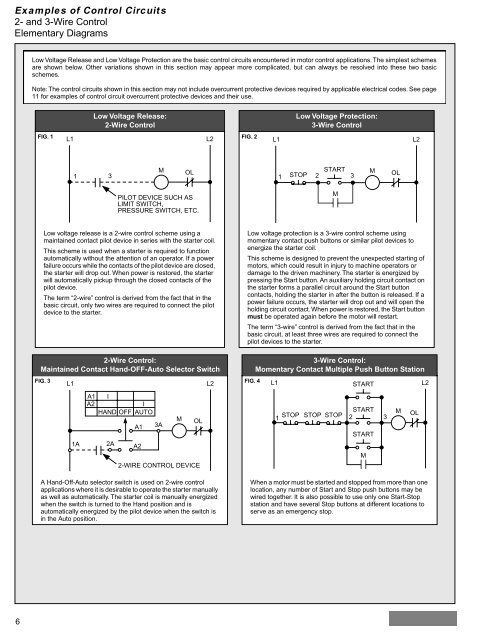
Examples of Control Circuits<br />
2- and 3-Wire Control<br />
Elementary <strong>Diagram</strong>s<br />
6<br />
Low Voltage Release and Low Voltage Protection are the basic control circuits encountered in motor control applications. The simplest schemes<br />
are shown below. Other variations shown in this section may appear more complicated, but can always be resolved into these two basic<br />
schemes.<br />
Note: The control circuits shown in this section may not include overcurrent protective devices required by applicable electrical codes. See page<br />
11 for examples of control circuit overcurrent protective devices and their use.<br />
Low Voltage Release:<br />
2-Wire Control<br />
FIG. 1<br />
L1 L2<br />
FIG. 2<br />
1<br />
3<br />
Low voltage release is a 2-wire control scheme using a<br />
maintained contact pilot device in series with the starter coil.<br />
This scheme is used when a starter is required to function<br />
automatically without the attention of an operator. If a power<br />
failure occurs while the contacts of the pilot device are closed,<br />
the starter will drop out. When power is restored, the starter<br />
will automatically pickup through the closed contacts of the<br />
pilot device.<br />
The term “2-wire” control is derived from the fact that in the<br />
basic circuit, only two wires are required to connect the pilot<br />
device to the starter.<br />
2-Wire Control:<br />
Maintained Contact Hand-OFF-Auto Selector Switch<br />
A Hand-Off-Auto selector switch is used on 2-wire control<br />
applications where it is desirable to operate the starter manually<br />
as well as automatically. The starter coil is manually energized<br />
when the switch is turned to the Hand position and is<br />
automatically energized by the pilot device when the switch is<br />
in the Auto position.<br />
M<br />
PILOT DEVICE SUCH AS<br />
LIMIT SWITCH,<br />
PRESSURE SWITCH, ETC.<br />
FIG. 3<br />
L1 L2<br />
FIG. 4<br />
A1 I<br />
A2<br />
I<br />
HAND OFF AUTO<br />
A1 3A<br />
M OL<br />
1A<br />
2A<br />
A2<br />
2-WIRE CONTROL DEVICE<br />
Low Voltage Protection:<br />
3-Wire Control<br />
L1 L2<br />
OL<br />
START M<br />
1 STOP 2 3<br />
M<br />
Low voltage protection is a 3-wire control scheme using<br />
momentary contact push buttons or similar pilot devices to<br />
energize the starter coil.<br />
This scheme is designed to prevent the unexpected starting of<br />
motors, which could result in injury to machine operators or<br />
damage to the driven machinery. The starter is energized by<br />
pressing the Start button. An auxiliary holding circuit contact on<br />
the starter forms a parallel circuit around the Start button<br />
contacts, holding the starter in after the button is released. If a<br />
power failure occurs, the starter will drop out and will open the<br />
holding circuit contact. When power is restored, the Start button<br />
must be operated again before the motor will restart.<br />
The term “3-wire” control is derived from the fact that in the<br />
basic circuit, at least three wires are required to connect the<br />
pilot devices to the starter.<br />
3-Wire Control:<br />
Momentary Contact Multiple Push Button Station<br />
When a motor must be started and stopped from more than one<br />
location, any number of Start and Stop push buttons may be<br />
wired together. It is also possible to use only one Start-Stop<br />
station and have several Stop buttons at different locations to<br />
serve as an emergency stop.<br />
OL<br />
L1 START<br />
L2<br />
1<br />
STOP STOP STOP<br />
START<br />
2<br />
START<br />
M<br />
3<br />
M<br />
OL