Undercarpet Power System
Undercarpet Power System
Undercarpet Power System

Create successful ePaper yourself
Turn your PDF publications into a flip-book with our unique Google optimized e-Paper software.
NOTE<br />
NOTE<br />
1. INTRODUCTION<br />
<strong>Undercarpet</strong><br />
<strong>Power</strong> <strong>System</strong><br />
2004 Tyco Electronics Corporation, Harrisburg, PA This controlled document is subject to change.<br />
All International Rights Reserved<br />
For latest revision, call the FAX/PRODUCT INFO number.<br />
AMP and Tyco are trademarks. *Trademark<br />
Other products, logos, and company names used are the property of their respective owners.<br />
Application Specification<br />
114–6008<br />
18 JUN 04 Rev D<br />
All numerical values are in metric units [with U.S. customary units in brackets]. Unless otherwise specified, dimensions<br />
have a tolerance of +0.13 [+.005] and angles have a tolerance of +2. Figures and illustrations are for identification<br />
only and are not drawn to scale.<br />
This specification covers the requirements for application of the <strong>Undercarpet</strong> <strong>Power</strong> <strong>System</strong> and is intended as<br />
an aid to architects, consulting engineers, building contractors, and electricians.<br />
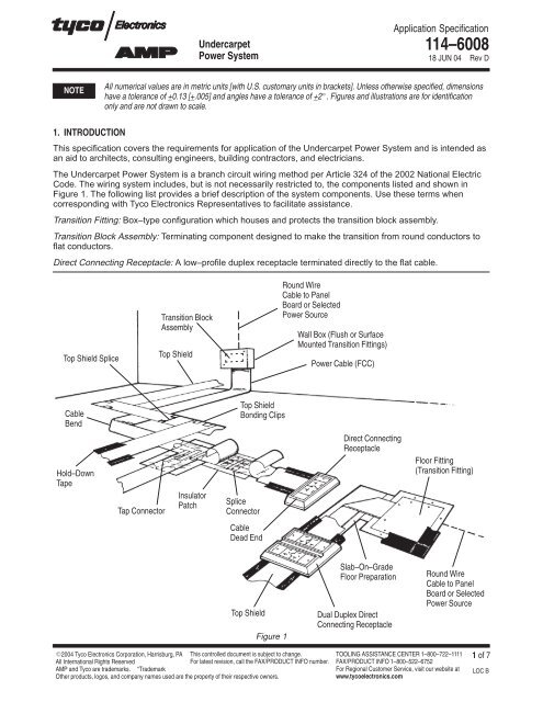
The <strong>Undercarpet</strong> <strong>Power</strong> <strong>System</strong> is a branch circuit wiring method per Article 324 of the 2002 National Electric<br />
Code. The wiring system includes, but is not necessarily restricted to, the components listed and shown in<br />
Figure 1. The following list provides a brief description of the system components. Use these terms when<br />
corresponding with Tyco Electronics Representatives to facilitate assistance.<br />
Transition Fitting: Box–type configuration which houses and protects the transition block assembly.<br />
Transition Block Assembly: Terminating component designed to make the transition from round conductors to<br />
flat conductors.<br />
Direct Connecting Receptacle: A low–profile duplex receptacle terminated directly to the flat cable.<br />
Top Shield Splice<br />
Cable<br />
Bend<br />
Hold–Down<br />
Tape<br />
Tap Connector<br />
Transition Block<br />
Assembly<br />
Top Shield<br />
Insulator<br />
Patch<br />
Top Shield<br />
Bonding Clips<br />
Splice<br />
Connector<br />
Cable<br />
Dead End<br />
Top Shield<br />
Figure 1<br />
Round Wire<br />
Cable to Panel<br />
Board or Selected<br />
<strong>Power</strong> Source<br />
Wall Box (Flush or Surface<br />
Mounted Transition Fittings)<br />
<strong>Power</strong> Cable (FCC)<br />
Direct Connecting<br />
Receptacle<br />
Slab–On–Grade<br />
Floor Preparation<br />
Dual Duplex Direct<br />
Connecting Receptacle<br />
Floor Fitting<br />
(Transition Fitting)<br />
Round Wire<br />
Cable to Panel<br />
Board or Selected<br />
<strong>Power</strong> Source<br />
TOOLING ASSISTANCE CENTER 1–800–722–1111<br />
FAX/PRODUCT INFO 1–800–522–6752<br />
For Regional Customer Service, visit our website at<br />
www.tycoelectronics.com<br />
1 of 7<br />
LOC B
2 of 7<br />
<strong>Undercarpet</strong> <strong>Power</strong> <strong>System</strong><br />
114–6008<br />
Floor Preparation: A polyvinyl sheet 0.25 mm [.010 in.] thick, designed to protect the cable from floor moisture,<br />
chemical reaction, and abrasion in slab–on–grade level applications.<br />
Flat Conductor Cable (FFC): Flat copper conductors between non–conductive laminated polyvinylchloride (pvc)<br />
with polyester film outer layer.<br />
Top Shield: Steel sheet 0.25 mm [.010 in.] thick, placed over flat conductor cable to provide physical protection<br />
and an additional electrical ground path.<br />
Tap Connector: Terminating device designed to electrically connect two flat conductor cables perpendicular to<br />
each other.<br />
Splice Connector: Terminating device designed to electrically connect two flat conductor cables to extend the<br />
cable length.<br />
Top Shield Bonding Clip: Connector used to splice and tap the top shield.<br />
Insulator Patch: Used to insulate tap and splice connectors and protect exposed conductor ends or areas.<br />
When corresponding with Tyco Electronics Personnel about this product, use the terminology provided in this<br />
specification to facilitate your inquiries for information. Basic terms and features of this product are provided in<br />
Figure 1.<br />
2. REFERENCE MATERIAL<br />
2.1. Revision Summary<br />
This paragraph is reserved for a revision summary covering the most recent additions and changes made to<br />
this specification which include the following:<br />
Per EC: 0990–0720–04<br />
Updated document to corporate requirements<br />
Changed article information in Section 1, INTRODUCTION<br />
Changed callouts in Figure 1<br />
Changed descriptive titles of components in Section 1, INTRODUCTION<br />
Changed DP–5566 to 409–5566 in Paragraph 2.5<br />
Changed text in Paragraphs 3.2.E.1–4, 3.2.F.2–5, 3.2.H.2, 5, 3.3, and Section 6, VISUAL AID<br />
Changed tooling information in Section 5, TOOLING<br />
Added new Figure 2 and renumbered<br />
2.2. Customer Assistance<br />
Reference Base Part Number 553239 and Product Code 1260 are representative numbers of <strong>Undercarpet</strong><br />
<strong>Power</strong> <strong>System</strong>. Use of these numbers will identify the product line and expedite your inquiries through a<br />
service network established to help you obtain product and tooling information. Such information can be<br />
obtained through a local Tyco Electronics Representative (Field Sales Engineer, Field Applications Engineer,<br />
etc.) or, after purchase, by calling the Tooling Assistance Center or the Tyco Electronics FAX/Product<br />
Information number at the bottom of page 1.<br />
2.3. Drawings<br />
Customer Drawings for specific products are available from the responsible Tyco Electronics Engineering<br />
Department via the service network. The information contained in Customer Drawings takes priority if there is a<br />
conflict with this document or with any other technical documentation supplied by Tyco Electronics.<br />
2.4. Specifications/Standards<br />
Various Product Specifications are available to cover test and performance requirements of the undercarpet<br />
components.<br />
Flat conductor cable is restricted to use under carpet squares in commercial facilities and must conform to the<br />
following standards, codes, and listings:<br />
Rev D
National Electrical Code<br />
<strong>Undercarpet</strong> <strong>Power</strong> <strong>System</strong><br />
National Fire Protection Association (NFPA) 70E.<br />
Underwriters Laboratories Inc. (UL)<br />
CSA International<br />
2.5. Instructional Material<br />
114–6008<br />
Tyco Electronics Instruction Sheets are available to cover installation and assembly of individual components.<br />
The instruction sheets are packaged with the components.<br />
<strong>Undercarpet</strong> Cabling <strong>System</strong>s (Layout and Planning Manual) 409–5566 includes floor preparation procedures,<br />
precautions and suggestions for proper layout techniques, considerations for economizing in material and labor<br />
requirements, physical and functional descriptions of all components in each system, techniques for preparing<br />
material take–off lists, and encapsulated installation instructions.<br />
3. REQUIREMENTS<br />
3.1. General<br />
Use all necessary care to avoid damaging the components of the <strong>Undercarpet</strong> <strong>Power</strong> <strong>System</strong> before, during,<br />
and after installation and to protect the installed work and materials from all other trades.<br />
Prior to all work involving the <strong>Undercarpet</strong> <strong>Power</strong> <strong>System</strong>, verify that the work of all other trades is complete to<br />
the point where this installation may properly commence.<br />
The time for <strong>Undercarpet</strong> <strong>Power</strong> <strong>System</strong> installation is just prior to carpet installation.<br />
1. In the event that the work of other trades is not complete, report the discrepancies to the engineer in<br />
charge.<br />
2. Do not proceed with installation in areas of discrepancy until all discrepancies have been fully<br />
resolved.<br />
3.2. Installation<br />
A. Drawing<br />
Before the <strong>Undercarpet</strong> <strong>Power</strong> <strong>System</strong> is actually installed, a system layout drawing (containing all<br />
elements of the circuit) should be made.<br />
B. Mounting the Transition Fitting/Transition Block Assembly<br />
Referring to the system layout drawing, mount the transition fitting and transition block assembly at the<br />
specified location, using fasteners appropriate for the type of fitting and the site construction encountered.<br />
Mounting details are provided on the instruction sheet packaged with the fitting.<br />
C. Preparing the Floor<br />
NOTE<br />
Uneven floors with irregularities must be leveled or patched.<br />
Concrete slabs must have all holes filled and projections removed to ensure a smooth surface.<br />
Porous floors must be sealed and free from grease, oil, and moisture.<br />
Clean floor thoroughly. Sweep and vacuum to remove all debris. Maintain clean area throughout<br />
installation.<br />
Do not install <strong>Undercarpet</strong> <strong>System</strong> on or in wet areas where water or liquids will be evident.<br />
Tyco Electronics does not warrant proper functions of installations that are not installed in accordance with preceding<br />
procedures.<br />
D. Marking the Floor<br />
Lay out the details of the branch circuit wiring on the floor using chalk lines and the appropriate symbols to<br />
indicate the cable run, transition block assembly locations, and tap points.<br />
Rev D 3 of 7
NOTE<br />
4 of 7<br />
<strong>Undercarpet</strong> <strong>Power</strong> <strong>System</strong><br />
114–6008<br />
It is recommended that necessary floor fitting anchor holes be drilled at this time so the floor may be cleared of debris<br />
before laying the bottom shield.<br />
E. Laying the Floor Preparation<br />
It is important that the bottom shield be installed on a clean, dry floor.<br />
1. Starting at the transition fitting, lay the floor preparation over the floor marking. Exercise caution to<br />
keep the floor preparation straight and smooth.<br />
2. Cut the floor preparation as necessary with scissors.<br />
3. Edge–tape the floor preparation to the floor periodically to hold it in place.<br />
4. Follow the instructions packaged with the floor preparation for installation specifics and<br />
recommendations.<br />
F. Installing the Flat Conductor Cable<br />
Cable installation should start at the transition block assembly. Specific instructions are packaged with the<br />
cable for all tasks in this phase of the installation.<br />
1. Connect cable to fitting transition block assembly.<br />
2. Center cable over floor preparation and tape to the floor at the transition point.<br />
3. Proceed with laying cable over floor preparation main run and edge–tape cable to the bottom shield<br />
every 1.8 to 3.7 m [6 to 12 ft.] to avoid shifting.<br />
4. To change the direction of the cable run, fold the cable at right or left angles over itself and press<br />
firmly to crease. No cutting is required. Corners should be centered on the floor preparation and taped.<br />
5. If the cable length is insufficient to complete the layout, splice the connectors to another cable to<br />
obtain the specified cable length.<br />
a. Maintain conductor size, configuration, and polarity.<br />
b. Trim cable ends square.<br />
c. Allow a maximum of 3.18 mm [.125 in.] between cable ends to be spliced.<br />
d. Terminate the splice connector with a Tyco Electronics Hand Tool. Install an insulator kit over the<br />
splice connectors.<br />
e. Edge–tape the cable in position after installing insulator kit.<br />
6. Lay tap circuits perpendicular to the main run.<br />
a. Trim tap cable end square.<br />
b. Allow a maximum of 3.18 mm [.125 in.] separation.<br />
c. Terminate the tap connector with a Tyco Electronics Hand Tool. Install an insulator kit over the tap<br />
connectors.<br />
d. Tape tap circuit cable in position, centered over the bottom shield.<br />
e. To change the direction of the tap circuit cable, fold cable at a right angle over itself and press<br />
firmly to crease. Corners should be centered on the bottom shield and taped.<br />
f. Where the tap circuit cable dead–ends at a floor fitting, trim the cable so that the squared end does<br />
not extend past the anchor screws by more than 12.7 mm [.500 in.].<br />
7. Apply connector patches.<br />
a. Care shall be taken when applying the patches to ensure that a proper environmentally sound seal<br />
is made.<br />
b. Patches are to be installed over splices, taps, and unterminated cable ends.<br />
G. Installing Floor Fittings<br />
In applications where floor fittings must be installed after cables are laid, edge tape both cable edges to<br />
the floor for a length of 0.6 m [2 ft.]. With the floor fitting centered across and between the taped edges,<br />
install the floor fitting as instructed in Paragraph 3.2.D. Sweep and vacuum to remove all debris prior to<br />
the tape removal and floor fitting installation.<br />
Rev D
<strong>Undercarpet</strong> <strong>Power</strong> <strong>System</strong><br />
Tape should partially overlap the flat conductor cable, bottom shield, and the floor.<br />
NOTE<br />
Protective tape prevents debris from getting under the cable and bottom shield while drilling the anchor holes.<br />
114–6008<br />
H. Installing Top Shield<br />
1. Begin laying the top shield main run at the transition fitting.<br />
a. Proceed to lay the top shield over the main runs, cross–taping it every 1.8 to 3.7 m [6 to 12 ft.].<br />
b. When laying the shield over the tap circuits, or when it is necessary to extend the length of the<br />
shield, overlap the shield 152 to 203 mm [6 to 8 in.] and place a piece of electrical tape on the flat<br />
conductor cable at the point where the lower piece of shield edge contacts the cable.<br />
2. Splice and tap the shield, using the top shield bonding clips.<br />
3. Terminate the top shield to the fittings and transition block assemblies.<br />
4. After installation of top shield, conduct an electrical check to ensure there are no shorts between the<br />
hot, neutral, and ground.<br />
5. Edge tape top shield to floor, along the complete installed cable run.<br />
I. Direct Connecting Receptacle (DCR) Installation<br />
1. DCR electrical fitting installation should begin after all debris has been removed from installation of<br />
the DCR mounting base plate and after the top shield has been installed.<br />
NOTE<br />
Instructions for installing DCR fittings are packaged with the DCR assembly<br />
2. Perform an electrical continuity check of the hot, neutral, and ground circuits.<br />
3. Install DCR cover fitting.<br />
J. Connecting Source <strong>Power</strong><br />
1. Instructions for connecting source power are packaged with the transition fitting block assembly<br />
covers.<br />
2. Recommended minimum size of interconnecting wire is 12 AWG copper for 12 AWG flat cable and 10<br />
AWG copper for 10 AWG flat cable.<br />
3. Match color–coded round conductors to color–coded flat conductors.<br />
4. A ground wire shall be connected from the ground binding screw on the transition block assembly to<br />
the ground terminal on or in the wall and floor electrical boxes or any other transition fitting.<br />
5. After the source power is connected, place a piece of electrical tape over the top shield edge and<br />
install the transition fitting cover.<br />
6. Apply power to the system and check the output of each receptacle for voltage and polarity.<br />
K. Installing Carpet Squares<br />
1. Coordinate work with electrical trades to ensure that electrical power is removed from flat conductor<br />
cable circuits while carpet is being installed.<br />
2. When cutting carpet to fit, it is important that a barrier be placed between the carpet and the cable to<br />
avoid accidentally cutting the cable.<br />
3. Place carpet squares directly over installed top shield.<br />
4. Cut and fit carpet to fit over or around installed fittings.<br />
3.3. Materials<br />
Cable: Factory laminated, abrasion resistant, color–coded, flat conductor cable.<br />
Top Shield: Corrosion–resistant, cold rolled steel strip.<br />
Rev D 5 of 7
6 of 7<br />
<strong>Undercarpet</strong> <strong>Power</strong> <strong>System</strong><br />
Floor Preparation: Yellow–colored, plasticized pvc sheet.<br />
Transition Fittings: Zinc–plated carbon steel, AISI type 1010.<br />
Transition Block Assemblies: R–10 RYTON molded blocks with associated insulators and hardware.<br />
Tap and Splice Cable Connectors and Top Shield Bonding Clips: Copper alloy.<br />
Floor Fitting Covers: Plastic molding compound.<br />
Transition Fitting Covers: Aluminum alloy, type 5052.<br />
3.4. Accessories<br />
Spray adhesive and hold–down tape are used to attach the top shield to the floor surface.<br />
4. QUALIFICATION<br />
4.1. Underwriters Laboratories Inc. (UL)<br />
<strong>Undercarpet</strong> <strong>Power</strong> cable is Listed under UL File Number E73212 and the fittings are Listed under UL File<br />
Number E73213 (per CSA International test methods).<br />
4.2. CSA International<br />
<strong>Undercarpet</strong> <strong>Power</strong> <strong>System</strong> is Certified under CSA International File Number C22.2 No. 222.<br />
114–6008<br />
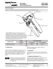
5. TOOLING<br />
<strong>Undercarpet</strong> Hand Tool 91384–1 is designed to terminate tap and splice connectors onto undercarpet power<br />
cables. Refer to Instruction Sheet 408–8860 for terminating procedures. See Figure 2.<br />
Lower Die<br />
Moving Jaw<br />
Moving Handle<br />
Figure 2<br />
Stationary Jaw<br />
Pivot Pin<br />
Stationary Handle<br />
Rev D
6. VISUAL AID<br />
<strong>Undercarpet</strong> <strong>Power</strong> <strong>System</strong><br />
114–6008<br />
Figure 3 shows a typical application of an <strong>Undercarpet</strong> <strong>Power</strong> <strong>System</strong>. This illustration should be used by<br />
installation personnel to ensure a correctly applied product. Applications which DO NOT appear correct should<br />
be inspected using the information in the preceding pages of this specification and in the instructional material<br />
shipped with the product.<br />
FIGURE 3. VISUAL AID<br />
Rev D 7 of 7