Fundamentals of Short-Circuit Protection for Transformers
Fundamentals of Short-Circuit Protection for Transformers
Fundamentals of Short-Circuit Protection for Transformers

You also want an ePaper? Increase the reach of your titles
YUMPU automatically turns print PDFs into web optimized ePapers that Google loves.
Now, if we introduce a magnetic core <strong>for</strong> the coil that<br />
creates a low-reluctance path <strong>for</strong> the magnetic flux, the<br />
amount <strong>of</strong> flux per ampere is high, and there<strong>for</strong>e the voltage<br />
opposing the current flow per ampere is high. The coil now<br />
appears as an almost open circuit. The current that flows in<br />
this case is the so-called magnetizing current that we <strong>of</strong>ten<br />
neglect in our calculations.<br />
Next, let us introduce a second coil on the magnetic core.<br />
This creates our basic two-winding trans<strong>for</strong>mer. Because the<br />
two coils are on the same core, the flux cutting them is nearly<br />
the same. Also, because <strong>of</strong> the concentrating effect <strong>of</strong> the<br />
magnetic core, the volts per turn in both coils are nearly the<br />
same. We use this characteristic to create the familiar<br />
trans<strong>for</strong>mer, which provides different voltage levels at the coil<br />
terminals by the ratio <strong>of</strong> the number <strong>of</strong> turns in each coil.<br />
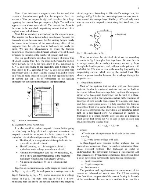
This is a good time to introduce the concepts <strong>of</strong> mutual flux<br />
(ΦM) and leakage flux (ΦL). The coupling between the coils is<br />
never perfect. In Fig. 1, the flux shown as ΦPL, generated by<br />
nP • iP, does not couple to the secondary coil. Similarly, the<br />
flux shown as ΦSL, generated by nS • iS, does not couple with<br />
the primary coil. This flux is called leakage flux, and it results<br />
in a voltage being induced in each coil that opposes the flow<br />
<strong>of</strong> current, per (1). This is represented as the leakage<br />
impedance in the equivalent circuit <strong>of</strong> the trans<strong>for</strong>mer.<br />
nP<br />
iP<br />
vP<br />
nS<br />
Fig. 1. Fluxes in a trans<strong>for</strong>mer.<br />
ΦPM<br />
ΦSM<br />
B. Magnetic <strong>Circuit</strong> Parameters<br />
It is also useful to review magnetic circuits be<strong>for</strong>e going<br />
on. One way to help electrical engineers understand the<br />
magnetic circuit is to equate its basic parameters to its<br />
equivalent electrical circuit parameters. Referring to (2):<br />
• The flux, Φ, in a magnetic circuit is equivalent to the<br />
current in an electric circuit.<br />
• The AT quantity, n • i , in a magnetic circuit is<br />
equivalent to the voltage in an electric circuit.<br />
• An unsaturated magnetic core has low reluctance, ℜ ,<br />
so it is like a conductor (reluctance is the magnetic<br />
equivalent <strong>of</strong> resistance in an electric circuit).<br />
• Air has high reluctance, ℜ , so it is like an open<br />
circuit.<br />
Fig. 2 is an electrical analogy to the magnetic circuit shown<br />
in Fig. 1. nP •iP = ATP<br />
is analogous to a voltage source in<br />
Fig. 2. Similarly, nS•iS = ATS<br />
is also analogous to a voltage<br />
source in Fig. 2. The right core leg in Fig. 1 is a lowreluctance<br />
path that shorts the top and bottom <strong>of</strong> the magnetic<br />
iS<br />
vS<br />
circuit together. According to Kirchh<strong>of</strong>f’s voltage law, the<br />
analogy in Fig. 2 is that the two voltage sources must sum to<br />
zero around the voltage loop. Similarly, ATP and ATS must<br />
sum to zero in the magnetic circuit along the closed loop core<br />
path.<br />
ATP<br />
ATS<br />
–<br />
–<br />
Fig. 2. Electrical analogy to Fig. 1.<br />
+<br />
+<br />
Φ<br />
<strong>Short</strong> <strong>Circuit</strong><br />
Now, let us close the electrical circuit on the secondary<br />
terminals in Fig. 1 through a load impedance. Because there is<br />
a voltage across the secondary terminals, current iS flows<br />
through the load impedance, and iP flows in the primary coil,<br />
such that the ATs sum to zero in the core leg (neglecting the<br />
magnetizing current, which sets up the mutual flux). This<br />
allows a power transfer between the windings through the<br />
magnetic core.<br />
C. Three-Phase Systems<br />
Most <strong>of</strong> the systems that we deal with are three-phase<br />
systems. Similar to electrical systems that can be built as<br />
three-wire delta or four-wire wye (star) systems, the magnetic<br />
circuit <strong>of</strong> a three-phase trans<strong>for</strong>mer can be built as a threelegged<br />
core or with a low-reluctance return path. Examples <strong>of</strong><br />
this type <strong>of</strong> core include four-legged, five-legged, shell type,<br />
and three single-phase cores. To help maintain the familiar<br />
concepts <strong>of</strong> three-wire versus four-wire systems, we will refer<br />
to all core construction that provides a low-reluctance return<br />
path as a four-legged core. As discussed in Section II,<br />
Subsection B, a return (fourth) core leg acts as a magnetic<br />
short circuit that <strong>for</strong>ces the AT to sum to zero on each core<br />
leg, neglecting the leakage flux:<br />
AT1 = AT2 = AT3 = 0<br />
(3)<br />
where:<br />
AT = the sum <strong>of</strong> ampere-turns in all coils on the same<br />
core leg.<br />
1, 2, 3 = the three core legs with coils.<br />
A three-legged core requires further analysis. We use<br />
symmetrical component theory to analyze unbalanced threephase<br />
electrical systems. This technique is useful in<br />
understanding the differences between a three-legged and<br />
four-legged core. Symmetrical components let us break down<br />
a set <strong>of</strong> three-phase currents into the following components:<br />
• Positive sequence<br />
• Negative sequence<br />
• Zero sequence<br />
The positive- and negative-sequence components <strong>of</strong> the<br />
current are balanced and sum to zero. The AT and resulting<br />
flux from these components <strong>of</strong> the current flowing in the coils<br />
<strong>of</strong> the trans<strong>for</strong>mer also sum to zero, so there is no need <strong>for</strong> a<br />
2