Brushless Alternators Wiring Instructions
Brushless Alternators Wiring Instructions
Brushless Alternators Wiring Instructions

Create successful ePaper yourself
Turn your PDF publications into a flip-book with our unique Google optimized e-Paper software.
Important: The information contained in this bulletin is intended for use by trained, professional technicians who have the proper<br />
tools, equipment, and training to perform the required maintenance described above. This information is NOT intended for ‘do-ityourselfers’,<br />
and you should not assume that this information applies to your equipment. If you have any questions regarding this<br />
information please visit our website at www.prestolite.com, or contact our technical service department at:<br />
Leece-Neville Heavy Duty Systems<br />
400 Main Street<br />
Arcade, NY 14009<br />
Page 1<br />
Technical Service<br />
Bulletin<br />
Source: Leece-Neville Heavy Duty Systems Division - Arcade, NY USA<br />
Date: FEBRUARY 01, 2010<br />
Bulletin No: TSB-1057<br />
Models: BLD2130GH, BLD2333GH, BLP2131GH, BLP2329GH, BLP2333GH,<br />
BLP2334GH, BLP2362GH, LBP2243GH<br />
Subject: Universal Alternator <strong>Wiring</strong> <strong>Instructions</strong><br />
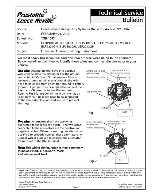
On most heavy trucks you will find one, two or three wires going to the alternator.<br />
Below we will explain how to identify these wires and connect the alternator to your<br />
vehicle.<br />
One wire: <strong>Alternators</strong> that have one positive<br />
wire connected to the alternator has the ground<br />
connected to it’s case. Our alternators have an<br />
isolated ground terminal so a ground wire will<br />
need to be added from alternator ground to battery<br />
ground. A jumper wire is supplied to connect the<br />
alternator (S) terminal to the (B+) terminal.<br />
Refer to Fig 1 for proper wiring. If vehicle has an<br />
ignition wire, it does not need to be connected<br />
to the alternator. Insulate and secure to prevent<br />
shorting.<br />
Two wire: <strong>Alternators</strong> that have two wires<br />
connected to them are self excite. The two wires<br />
connected to the alternators are the positive and<br />
negative cables. When connecting our alternators<br />
use Fig 2 to properly connect these alternators. A<br />
jumper wire is supplied to connect the alternator<br />
(S) terminal to the (B+) terminal.<br />
Note: This wiring configuration is most commonly<br />
found on Peterbilt, Kenworth, Mack<br />
and International Truck.<br />
Jumper wire supplied<br />
with alternator<br />
Lamp Terminal (L or I)<br />
No connection needed<br />
Remote voltage sense (S) C<br />
Add ground wire<br />
Fig 1<br />
Jumper wire supplied<br />
with alternator<br />
AC Taps (R)<br />
A<br />
Lamp Terminal (L or I)<br />
No connection needed<br />
Remote voltage sense (S) C<br />
Fig 2<br />
AC Taps (R)<br />
A<br />
Phone/Fax: (866) 288-9853<br />
webmail@prestolite.com
Date: FEBRUARY 1, 2010<br />
Bulletin No: TSB-1057<br />
Three wire: <strong>Alternators</strong> that have three wires connected<br />
to them could be ignition excite or self excite with<br />
remote voltage sense or lamp.<br />
To determine which type of alternator you have follow<br />
the steps below.<br />
Ignition excite alternators w/o lamp: The three wires<br />
are the positive, negative cables and a third smaller<br />
gauge wire connected to the alternator IGN or (I)<br />
terminal. Voltage will be present to the ignition terminal<br />
only when the vehicle key is in the run position. If your<br />
vehicle has an ignition wire, do not connect it to the<br />
alternator. Insulate and secure to prevent shorting. All<br />
that is needed is the main positive, negative cables<br />
and jumper wire connected to the alternator (S) and B+<br />
terminals in order for it to operate. (Fig 2)<br />
Note: Verify that vehicle does not have an indicator<br />
lamp on the dash. If vehicle has an indicator lamp refer<br />
to Self/ Ignition excite w lamp procedure.<br />
Self/ Ignition excite w lamp: The three wires are the<br />
positive, negative cables and a third smaller gauge wire<br />
connected to the alternator IGN or (I) terminal. Verify<br />
that vehicle has a lamp on the dash before proceeding.<br />
Wire alternator per (Fig 3)<br />
Note: This wiring is most commonly found on Volvo<br />
vehicles.<br />
Remote voltage sense alternators: The three wires<br />
connected to the alternator are the positive, negative<br />
cables and a third smaller gauge wire connected to the<br />
alternator remote sense or (S) terminal. To determine<br />
if your vehicle has remote sense, voltage will always be<br />
present on this terminal at all times. If your vehicle falls<br />
into this classification please wire your alternator per<br />
(Fig. 3a).<br />
Note: This wiring is most commonly found on<br />
Freightliner vehicles.<br />
Important: The information contained in this bulletin is intended for use by trained, professional technicians who have the proper<br />
tools, equipment, and training to perform the required maintenance described above. This information is NOT intended for ‘do-ityourselfers’,<br />
and you should not assume that this information applies to your equipment. If you have any questions regarding this<br />
information please visit our website at www.prestolite.com, or contact our technical service department at:<br />
Leece-Neville Heavy Duty Systems<br />
7585 Empire Drive<br />
Florence, KY 41042<br />
B+<br />
Page 2<br />
IGN<br />
Wire is part of vehicle’s<br />
wiring<br />
Remote voltage sense (S)<br />
Technical Service<br />
Bulletin<br />
Wires are part of vehicle’s wiring<br />
Jumper wire supplied with alternator<br />
LAMP<br />
A<br />
Lamp Terminal(L or I)<br />
No connection needed<br />
A<br />
Remote voltage sense (S)<br />
Lamp Terminal (L or I)<br />
AC Taps (R)<br />
Fig 3<br />
AC Taps (R)<br />
Fig 3a.<br />
Phone/Fax: (866) 288-9853<br />
webmail@prestolite.com<br />
C<br />
C
Date: FEBRUARY 1, 2010<br />
Bulletin No: TSB-1057<br />
Note for all wiring configurations: Alternator lamp<br />
terminals can be called (L) or (I).<br />
It is very important to make sure a warning lamp is<br />
present before connecting to the alternators lamp<br />
terminal. If a lamp is not present in the circuit and B+<br />
is connected directly to the alternators (L) terminal<br />
damage to the regulator will be the result.<br />
Wire identification tips:<br />
Important: The information contained in this bulletin is intended for use by trained, professional technicians who have the proper<br />
tools, equipment, and training to perform the required maintenance described above. This information is NOT intended for ‘do-ityourselfers’,<br />
and you should not assume that this information applies to your equipment. If you have any questions regarding this<br />
information please visit our website at www.prestolite.com, or contact our technical service department at:<br />
Leece-Neville Heavy Duty Systems<br />
400 Main Street<br />
Arcade, NY 14009<br />
Page 3<br />
Technical Service<br />
Bulletin<br />
Remote voltage sense (S): Small gauge wire 16AWG or larger that has voltage present at all<br />
times. Usually is connected directly to battery positive.<br />
Ignition excite (I): Small gauge wire 16AWG or larger that has voltage present only when the<br />
ignition switch is in the run mode. Check vehicle dash for an alternator warning lamp. If warning<br />
lamp is present then this wire can be connected to the alternators lamp terminal. If not, then<br />
insulate, secure and do not connect to the alternator.<br />
Positive cable: Large gauge wire 4AWG or larger that has voltage present at all times. Usually red<br />
in color.<br />
Negative cable: Large gauge wire 4AWG or larger connected to battery or chassis ground.<br />
AC or Relay (R) cable: If none of the above test help identify a wire then it could get connected<br />
to the alternators AC terminal. Usually this wire operates a relay or tachometer and should be<br />
verified before being connected to the alternator.<br />
To determine the proper wire sizes to use on your application please refer to TSB-1001<br />
Phone/Fax: (866) 288-9853<br />
webmail@prestolite.com