

DGC Brushless Excitation - Emerson Process Management
DGC Brushless Excitation - Emerson Process Management
DGC Brushless Excitation - Emerson Process Management

Create successful ePaper yourself
Turn your PDF publications into a flip-book with our unique Google optimized e-Paper software.
The contingency conditions are:<br />
• Any Alarm that enforces the NO AUTO restriction i.e., Bad PT’s<br />
• Customer input requests a Regulator Trip<br />
• OXP requests a Regulator Trip<br />
• VHP requests a Regulator Trip<br />
<strong>DGC</strong> <strong>Brushless</strong> <strong>Excitation</strong><br />
System Description<br />
In the FORCED Mode, the OFF lamp blinks at approximately 2 Hz until the fault condition is cleared<br />
and the Operator returns the control switch to TEST position.<br />
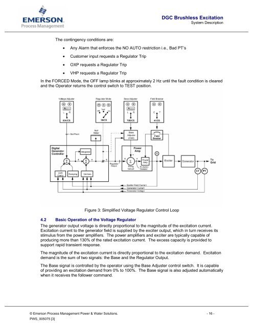
Figure 3: Simplified Voltage Regulator Control Loop<br />
4.2 Basic Operation of the Voltage Regulator<br />
The generator output voltage is directly proportional to the magnitude of the excitation current.<br />
<strong>Excitation</strong> current to the generator field is supplied by the exciter output, which in turn receives its<br />
stimulus from the power amplifiers. The power amplifiers and exciter are typically capable of<br />
producing more than 130% of the rated excitation current. The excess capacity is provided to<br />
support rapid transient response.<br />
The magnitude of the excitation current is directly proportional to the excitation demand. <strong>Excitation</strong><br />
demand is the sum of two signals: the Base and the Regulator Output.<br />
The Base signal is controlled by the operator using the Base Adjuster control switch. It is capable<br />
of providing an excitation demand from 0% to 100%. The Base signal is also adjusted automatically<br />
when it receives the follower command.<br />
© <strong>Emerson</strong> <strong>Process</strong> <strong>Management</strong> Power & Water Solutions. - 16 -<br />
PWS_005075 [3]


