

DGC Brushless Excitation - Emerson Process Management
DGC Brushless Excitation - Emerson Process Management
DGC Brushless Excitation - Emerson Process Management

You also want an ePaper? Increase the reach of your titles
YUMPU automatically turns print PDFs into web optimized ePapers that Google loves.
<strong>DGC</strong> <strong>Brushless</strong> <strong>Excitation</strong><br />
System Description<br />
The IOICU receives and conditions digital input signals from the field in three ranges: 125 VDC, 15<br />
VDC and 5 VDC and converts them to the 5 VDC logic states. Digital inputs are optically isolated.<br />
The IOICU converts the logic states to dry relay contacts and provides the capability to “tristate”<br />
each of the digital outputs as part of the redundancy features of the <strong>DGC</strong>.<br />
3.3.d VME Power Supply<br />
Each <strong>DGC</strong> channel is equipped with its own rack mounted, quad output, power supply module.<br />
Each Power Supply is fed by two independent power sources; Station 125 VDC system and an<br />
independent 120 VAC source.<br />
Each Power Supply provides dedicated power to its respective channel of the <strong>DGC</strong> at +5 VDC, +12<br />
VDC and -12 VDC. Each power supply also provides auctioneered +48 VDC to the IOICU<br />
Backplane for distribution to the Field Interface Panel and the cooling fans.<br />
3.3.e Network Hub Module<br />
The Network Hub Module provides a hub for Ethernet communication with the <strong>DGC</strong> channels. The<br />
two single board computers also use the network connection for inter-processor communications.<br />
The network connection is also used by the <strong>DGC</strong> configuration software and optional SCADA<br />
software.<br />
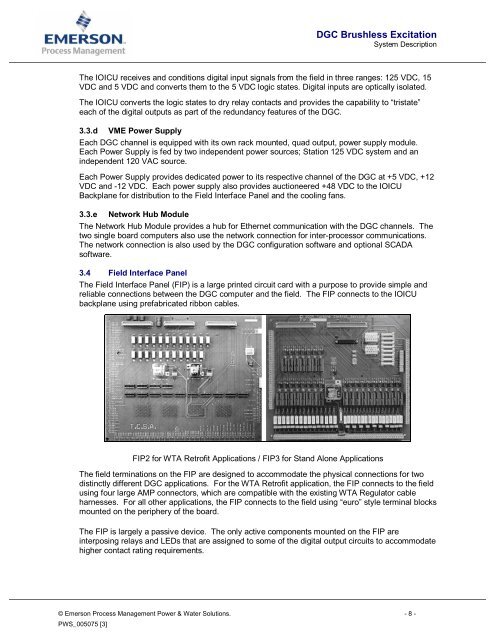
3.4 Field Interface Panel<br />
The Field Interface Panel (FIP) is a large printed circuit card with a purpose to provide simple and<br />
reliable connections between the <strong>DGC</strong> computer and the field. The FIP connects to the IOICU<br />
backplane using prefabricated ribbon cables.<br />
FIP2 for WTA Retrofit Applications / FIP3 for Stand Alone Applications<br />
The field terminations on the FIP are designed to accommodate the physical connections for two<br />
distinctly different <strong>DGC</strong> applications. For the WTA Retrofit application, the FIP connects to the field<br />
using four large AMP connectors, which are compatible with the existing WTA Regulator cable<br />
harnesses. For all other applications, the FIP connects to the field using “euro” style terminal blocks<br />
mounted on the periphery of the board.<br />
The FIP is largely a passive device. The only active components mounted on the FIP are<br />
interposing relays and LEDs that are assigned to some of the digital output circuits to accommodate<br />
higher contact rating requirements.<br />
© <strong>Emerson</strong> <strong>Process</strong> <strong>Management</strong> Power & Water Solutions. - 8 -<br />
PWS_005075 [3]


