

FRONT (Page 1) - Fusite
FRONT (Page 1) - Fusite
FRONT (Page 1) - Fusite

You also want an ePaper? Increase the reach of your titles
YUMPU automatically turns print PDFs into web optimized ePapers that Google loves.
®<br />
TECH-DATA<br />
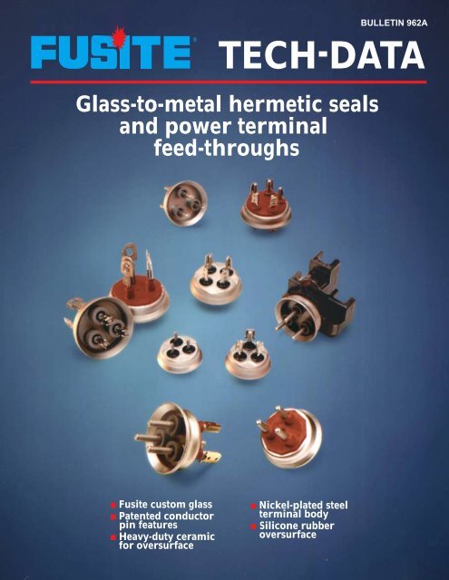
Glass-to-metal hermetic seals<br />
and power terminal<br />
feed-throughs<br />
■ <strong>Fusite</strong> custom glass<br />
■ Patented conductor<br />
pin features<br />
■ Heavy-duty ceramic<br />
for oversurface<br />
■ Nickel-plated steel<br />
terminal body<br />
■ Silicone rubber<br />
oversurface<br />
BULLETIN 962A
Glass-to-metal<br />
hermetic seals<br />
and power<br />
terminal<br />
feed-throughs<br />
Terminal Models<br />
Fractional, 600<br />
and 700 Series<br />
These <strong>Fusite</strong> terminals are<br />
designed for high reliability Air<br />
Conditioning and Refrigeration<br />
Compressors. Many incorporate<br />
industry’s most innovative engineering<br />
features, including:<br />
■ Patented groove is designed to<br />
open at high in-rush currents.<br />
(This design is not a substitute<br />
for compressor safety devices<br />
and circuit protection.)<br />
■ Custom-smelted <strong>Fusite</strong> proprietory<br />
glass designed for complete and<br />
reliable hermeticity.<br />
■ Heavy-duty ceramic insulator for<br />
electrical oversurface on the<br />
inside of the compressor.<br />
■ Molded silicone rubber oversurface<br />
for the outside of the compressor,<br />
bonded to the terminal.<br />
■ Solid pin and high conductivity<br />
copper core pin models available<br />
for various applications.<br />
Minimum Ratings<br />
Hydrostatic<br />
Pressure: .................... UL - 2250 psi<br />
Hermeticity: ................1 x 10 (-7) Std.<br />
CC/Sec. of Helium<br />
Dielectric Voltage: ......Min. 2500V with<br />
10,000 Megohms<br />
at 500VDC<br />
© 1996 <strong>Fusite</strong> Division of Emerson Electric Co.<br />
<strong>Fusite</strong> is a registered trademark of Emerson Electric Co.<br />
®<br />
PART # A B C<br />
393-37 .344 [8.74] .547 [13.89] 1.281 [32.54]<br />
393-38 .266 [6.76] .406 [10.31] 1.062 [26.97]<br />
393-95 .266 [6.76] .547 [13.89] 1.203 [30.56]<br />
TERMINALS - 393 FRACTIONAL SERIES<br />
PART # A B<br />
393-694 .452 [11.48] 1.510 [38.36]<br />
393-677 .530 [13.46] 1.590 [40.39]<br />
TERMINALS - 393-600 SERIES<br />
TERMINALS - 393-700 SERIES<br />
Nonagon<br />
pad available<br />
on 393-600<br />
and 393-700<br />
Copper Core<br />
Models<br />
footnoted 4.<br />
Nonagon<br />
pad available<br />
on 393-600<br />
and 393-700<br />
Copper Core<br />
Models<br />
footnoted 4.<br />
PART # A B<br />
3B3-635 .765 [19.43] 1.700 [43.18]<br />
3B3-637 .875 [22.23] 1.810 [45.97]<br />
TERMINALS - 3B3-600 SERIES<br />
TERMINALS - 3K3-600 SERIES<br />
0.459<br />
0.125 [3.18]<br />
0.059 [1.50]<br />
[11.66]<br />
1.282 [32.56]<br />
0.059 [1.50]<br />
0.469<br />
[11.66]<br />
0.937 [23.80]<br />
MAX.<br />
AROUND<br />
INSULATORS<br />
A<br />
B<br />
0.125 [3.18]<br />
0.459<br />
[11.66]<br />
0.937 [23.80]<br />
0.125 [3.18]<br />
45˚<br />
0.390 [9.91]<br />
0.250 [6.35]<br />
90˚<br />
A<br />
1.282 [32.56]<br />
45 ˚<br />
1.282 [32.56]<br />
B<br />
C<br />
1.510 [38.36]<br />
0.391 [9.93]<br />
0.250 [6.35]<br />
1.112 [28.24]<br />
0.090 [2.29]<br />
0.238 [6.05]<br />
1.112 [28.24]<br />
0.260 [6.60]<br />
0.670 REF. [17.02]<br />
0.059 [1.50] 0.250 [6.35]<br />
MAX.<br />
AROUND<br />
INSULATORS<br />
45 ˚<br />
0.059 [1.50]<br />
45˚ 1.480 [37.59]<br />
0.452<br />
[11.48]<br />
0.391 [9.93]<br />
0.670<br />
REF.<br />
0.391 [9.93]<br />
0.250 [6.35]<br />
0.238 [6.05]<br />
[13.46]<br />
1.112 [28.24]<br />
0.260 [6.60]<br />
[17.02]<br />
1.312 [33.32]<br />
0.272 [6.91]<br />
J P<br />
90<br />
[13.46]<br />
˚<br />
F<br />
U<br />
R<br />
T<br />
S I E<br />
0.530<br />
PAT' D<br />
C<br />
PAT'D<br />
C<br />
FU S<br />
R<br />
C<br />
I T E<br />
0.530<br />
0.5954<br />
[15.123]<br />
1.100 [27.94]<br />
MAX.<br />
AROUND<br />
INSULATORS<br />
0.530<br />
[13.46]<br />
B<br />
A<br />
0.421 [10.69]<br />
[17.45] 0.687<br />
0.085 [2.16]<br />
0.125 [3.18] 45°<br />
0.7057<br />
[17.925]<br />
1.920 [48.77]<br />
0.505<br />
[12.83]<br />
1.820 [46.23]<br />
0.500 [12.70]<br />
0.280 [7.11] 1.700 [43.18]<br />
0.812<br />
REF.<br />
0.280 [7.11]<br />
0.405 [10.29]<br />
[20.70]<br />
[20.62]<br />
Note: Dimensions shown are in inches with millimeter dimensions in parentheses.<br />
Ceramic Steel<br />
Glass Rubber<br />
90<br />
˚<br />
PAT ' D<br />
C<br />
0.815<br />
Drawings are representative of <strong>Fusite</strong> models.<br />
All data is subject to change. Consult latest<br />
<strong>Fusite</strong> engineering drawings for current<br />
specifications.<br />
PAT' D<br />
C<br />
R<br />
F US I<br />
F US<br />
F U S<br />
T E<br />
R<br />
I T E<br />
0.530<br />
U R<br />
R<br />
I T E<br />
U R<br />
U R<br />
U R<br />
[13.46]
Model 1<br />
Pin<br />
Material<br />
400 Series<br />
SS<br />
393-794 Solid Pins Pins 35 1.510 (38.36)<br />
For over<br />
393-774 Cu Core 4 Pins Pins 2000 VA & 50 3/8 (9.5) 3/16 (4.8) 1/4 (6.4) 1/8 (3.2) .125 (3.18) 1.510 (38.36)<br />
up to 300 V<br />
393-798 Cu Core 4 Pins Tabs 50 1.510 (38.36)<br />
1 Models listed are representative models.<br />
2 Terminals are recognized by Underwriters Laboratories File SA3716 -<br />
Per UL Standard 984<br />
3 Maximum Operating Current values were established under laboratory<br />
conditions and serve as guidelines only. Individual applications must be<br />
tested to determine the effect of specific variables. Tests were conducted<br />
using standard gauge wire and high conductivity connectors, rated for their<br />
applications. It is very important to use the proper wire size for a given<br />
compressor operating current. Wire size and connector type greatly influence<br />
the pin temperature, especially in over-current conditions.<br />
4 These terminals are available with nonagon pads (shown at left).<br />
Terminations<br />
Outside Inside<br />
UL Rating<br />
2<br />
Maximum<br />
Operating<br />
Current<br />
Amps 3<br />
Minimum Spacing Inches (mm)<br />
Oversurface Through Air<br />
Outside Inside Outside Inside<br />
Pin Dia.<br />
Inches (mm)<br />
Pin Length<br />
Inches (mm)<br />
393-38 Solid Pins Pins For up to 20 1.062 (26.97)<br />
2000 VA &<br />
393-95 Solid Tabs Pins up to 300 V, 22 1/8 (3.2) 3/32 (2.4) 1/8 (3.2) 1/16 (1.6) .090 (2.29) 1.203 (30.56)<br />
and for over<br />
393-37 Solid Tabs Tabs 2000 VA 25 1.281 (32.54)<br />
& up to<br />
150V<br />
393-677 Cu Core 4 Tabs Pins 50 1.590 (40.39)<br />
For over<br />
393-694 Solid Tabs Pins 2000 VA & 35 1.510 (38.36)<br />
up to 300 V<br />
393-674 Cu Core 4 Tabs Pins 50 3/8 (9.5) 3/16 (4.8) 1/4 (6.4) 1/8 (3.2) .125 (3.18) 1.510 (38.36)<br />
393-698 Cu Core 4 Tabs Tabs 50 1.510 (38.36)<br />
3B3-640 Solid Tabs Pins 35 1.810 (45.97)<br />
3B3-637 Cu Core Tabs Pins 55 1.810 (45.97)<br />
For over<br />
3B3-634T Solid Tabs Tabs 2000 VA 35 1.810 (45.97)<br />
& up to<br />
3B3-619 Cu Core Tabs Tabs 600 V 55 1/2 (12.7) 1/4 (6.4) 3/8 (9.5) 3/16 (4.8) .125 (3.18) 1.810 (45.97)<br />
3B3-635 Cu Core Straps Pins 65 1.700 (43.18)<br />
3B3-620 Cu Core Straps Tabs 60 1.700 (43.18)<br />
3K3-602 Cu Core Double Pins 80 .187 (4.75) 1.820 (46.23)<br />
Straps<br />
For over<br />
3K3-601 Cu Core Double Double 2000 VA 125 1/2 (12.7) 1/4 (6.4) 3/8 (9.5) 3/16 (4.8) .187 (4.75) 1.820 (46.23)<br />
Straps Tabs & up to<br />
600V<br />
3K3H-600 Cu Core Double Double 130 .243 (6.17) 1.820 (46.23)<br />
Straps Tabs<br />
0.062 [1.57]<br />
0.312 [7.92]<br />
0.160 [4.06]<br />
TAB DETAIL STRAP DETAIL<br />
0.656 [16.66]<br />
ø0.065/0.080 [1.65/2.03]<br />
0.344 [8.74]<br />
0.040 [1.02] x 45˚<br />
0.250 [6.35]<br />
0.307 [7.80] MIN.<br />
0.032 [0.81]<br />
0.104 [2.64]<br />
0.218 [5.54]<br />
0.437 [11.10]<br />
0.030 [0.76]
Installation,Operation and Shipping<br />
1. Excessive shocks to the terminal<br />
must be avoided since mechanical<br />
stress can damage the glass and/or<br />
ceramic. Damage may result in hermetic<br />
failure or loss of terminal performance.<br />
2. Precautions are required to prevent<br />
striking or bending of pins. Bent or<br />
damaged pins may result in loss of<br />
hermeticity or terminal performance.<br />
3. Terminals must not be overheated<br />
during brazing or welding operations.<br />
The temperature of the metal adjacent<br />
to the glass must not exceed 400°F.<br />
4. It is important to select the proper<br />
terminal for each application. Considerations<br />
include maximum operating<br />
currents, locked rotor currents,<br />
time and protection circuitry. Since<br />
customer designs vary as to terminal<br />
location, lead size, return line locations<br />
and compressor types, <strong>Fusite</strong><br />
cannot provide specific data on every<br />
compressor configuration. The<br />
attached data tables are general<br />
guidelines only and not specific<br />
application recommendations. For<br />
assistance in terminal selection, contact<br />
<strong>Fusite</strong> Engineering.<br />
Bulletin 962A<br />
Hermetic Terminal Precautions<br />
5. Compressors and systems should<br />
be designed with appropriate electrical<br />
overload and thermal overload protection.<br />
Locked rotor currents often run 5<br />
times as high as operating currents,<br />
and in some cases even higher. If<br />
such high currents are allowed to continue<br />
for any length of time, severe<br />
damage or personal injury may result.<br />
High currents raise the terminal pin<br />
temperatures, which may result in failure<br />
of wire insulation, breakdown of<br />
coolant-oil mixture causing possible<br />
electrical contamination, or softening<br />
of the glass seal resulting in hermetic<br />
failure.<br />
6. Lead size and connector configuration<br />
can effect terminal operating<br />
temperature. Using larger wires<br />
increases the heat sink effect and lowers<br />
pin temperatures. Proper connector<br />
selection also reduces contact<br />
resistance and lowers pin temperatures.<br />
General Instructions<br />
Improper handling or servicing may<br />
cause hermetic terminal failure. The<br />
glass seal of the terminal may be<br />
damaged and allow leakage of oil and<br />
Where Glass Seals Metal<br />
®<br />
FUSITE DIVISION<br />
EMERSON ELECTRIC CO.<br />
6000 FERNVIEW AVENUE<br />
CINCINNATI, OHIO 45212 U.S.A.<br />
Telephone 513-731-2020 • Fax 513-631-6456<br />
International Locations: GOTEMBA, JAPAN •<br />
ALMELO, HOLLAND • BAO’AN, CHINA<br />
refrigerant. If electrical power is<br />
applied under these conditions, a hazardous<br />
condition can be initiated and<br />
may result in serious personal injury<br />
and/or property damage.<br />
To protect against this potential hazard,<br />
personnel should be advised of<br />
these conditions and take the following<br />
precautions:<br />
1. Always refer to compressor manufacturer’s<br />
installation, operating and<br />
service instructions.<br />
2. <strong>Fusite</strong> terminals are not field serviceable<br />
or repairable. Replace compressor<br />
if required.<br />
3. Do not remove the junction box<br />
cover until electrical power to the unit<br />
has been turned off.<br />
4. Do not start the compressor without<br />
the junction box cover properly locked<br />
in place.<br />
To protect further against compressor<br />
failure hazards, consult factory technical<br />
manuals. In addition, consult and<br />
follow all manufacturers’ warning<br />
labels mounted adjacent to the compressor<br />
junction box. Contact <strong>Fusite</strong><br />
for other information regarding<br />
Terminal Precautions.<br />
All sales are subject to <strong>Fusite</strong>’s Terms & Conditions in effect at the time of shipment. A copy will be provided upon request.<br />
Printed in U.S.A.