Medium-Voltage Circuit Breaker-Type Automatic ... - Russelectric
Medium-Voltage Circuit Breaker-Type Automatic ... - Russelectric
Medium-Voltage Circuit Breaker-Type Automatic ... - Russelectric

Create successful ePaper yourself
Turn your PDF publications into a flip-book with our unique Google optimized e-Paper software.
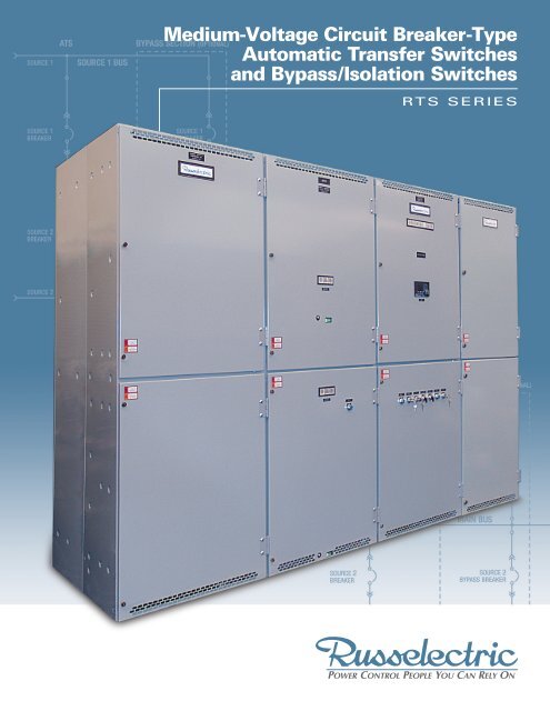
<strong>Medium</strong>-<strong>Voltage</strong> <strong>Circuit</strong> <strong>Breaker</strong>-<strong>Type</strong><br />
<strong>Automatic</strong> Transfer Switches<br />
and Bypass/Isolation Switches<br />
RTS SERIES
2<br />
RTS Series <strong>Medium</strong>-<strong>Voltage</strong> <strong>Circuit</strong> <strong>Breaker</strong>-<strong>Type</strong> <strong>Automatic</strong> Transfer<br />
<strong>Circuit</strong> breaker medium-voltage<br />
automatic transfer switches<br />
and bypass/isolation switches<br />
are tested, listed, and labeled by<br />
UL under UL 1008A – Over 600 V<br />
<strong>Russelectric</strong> RPTCS programmable<br />
microprocessor-based control system<br />
Metal-clad construction<br />
3-pole construction<br />
UL Tested, Listed, and Labeled <strong>Medium</strong>-<br />
<strong>Voltage</strong> <strong>Automatic</strong> Transfer Switches<br />
<strong>Russelectric</strong> was the industry leader<br />
in obtaining UL listing for its mediumvoltage<br />
transfer switchgear. All<br />
<strong>Russelectric</strong> RTS Series circuit breaker<br />
automatic transfer switches have been<br />
fully UL tested, listed, and labeled<br />
under UL 1008A. In addition, all<br />
<strong>Russelectric</strong> medium-voltage transfer<br />
switchgear (operating above 600 volts<br />
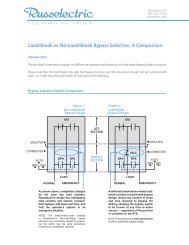
SOURCE 1<br />
SOURCE 1<br />
BREAKER<br />
SOURCE 2<br />
BREAKER<br />
SOURCE 2<br />
ATS BYPASS SECTION (OPTIONAL)<br />
SOURCE 1 BUS<br />
SOURCE 2 BUS<br />
SOURCE 1<br />
BYPASS BREAKER<br />
MAIN BUS<br />
SOURCE 2<br />
BYPASS BREAKER<br />
and below 15 kV) is listed per UL<br />
category “<strong>Circuit</strong> <strong>Breaker</strong>s and<br />
Metal-Clad Switchgear – Over 600<br />
Volts (DLAH)”. It is also designed,<br />
manufactured, and tested to meet<br />
or exceed stringent IEEE, NEMA,<br />
and ANSI standards.<br />
<strong>Russelectric</strong> RTS Series mediumvoltage<br />
ATSs are rugged, high-speed<br />
switching devices designed to<br />
transfer electrical loads from a normal<br />
LOAD<br />
<strong>Voltage</strong> Class<br />
kV<br />
Short-<strong>Circuit</strong> Withstand<br />
kA rms<br />
Power Frequency hz<br />
power source to an emergency power<br />
source upon reduction or loss of<br />
voltage and to retransfer loads when<br />
normal power is restored.<br />
Supervised by the advanced RPTCS<br />
microprocessor control, <strong>Russelectric</strong><br />
<strong>Medium</strong>-<strong>Voltage</strong> <strong>Circuit</strong> <strong>Breaker</strong><br />
<strong>Automatic</strong> Transfer Switches direct<br />
the flow of electric power through the<br />
carefully timed opening/closing of<br />
circuit breakers.<br />
Ratings: <strong>Circuit</strong> <strong>Breaker</strong>-<strong>Type</strong> <strong>Medium</strong>-<strong>Voltage</strong><br />
<strong>Automatic</strong> Transfer Switches<br />
Continuous Current Rating Amperes<br />
Ratings 1200 A 2000 A 1200 A 2000 A<br />
5 5 15 15<br />
40 or<br />
50<br />
40 or<br />
50<br />
25, 40,<br />
or 50<br />
25, 40,<br />
or 50<br />
60 60 60 60
Switches and Bypass/Isolation Switches<br />
A<br />
Designed, for Maximum Safety and<br />
Operating Simplicity<br />
Switches are designed to provide<br />
maximum protection for operators and<br />
maintenance personnel and to minimize<br />
the danger of operator error. Drawout<br />
modules, metal-clad construction,<br />
segregation of controls from power<br />
elements, and separately accessible<br />
grounded compartments are all part of<br />
<strong>Russelectric</strong>’s design safety philosophy.<br />
All switches are designed for unattended<br />
automatic operation, but include controls<br />
for manual operation. Designs provide<br />
accessibility for maintenance, troubleshooting,<br />
and component replacement.<br />
All switches are factory tested for<br />
functionality prior to shipment.<br />
Interconnect wiring diagrams enable<br />
proper interfacing of switches with the<br />
prime mover and other equipment.<br />
Buswork | A<br />
All bus is formed, cut, and punched<br />
before being insulated with high-dielectric<br />
epoxy coating to guarantee the integrity<br />
of the insulation and ensure maximum<br />
performance. Busbars pass through<br />
track-resistant, polyester glass barriers<br />
between cubicles. Main bus joints have<br />
silver-plated connections and are<br />
insulated with preformed boots.<br />
B<br />
C<br />
Drawout <strong>Circuit</strong> <strong>Breaker</strong>s | D<br />
All circuit breakers are enclosed in drawout<br />
compartments. Self-aligning mating<br />
contacts ensure proper connections.<br />
Safety interlocks and closed door racking<br />
are standard. Stationary contacts have<br />
automatic shutter covers for safety.<br />
Current Transformers<br />
Current transformers are located behind<br />
an automatic shutter barrier that isolates<br />
the primary disconnects when the breaker<br />
is in the disconnect position. Up to 12<br />
CTs per breaker can be accommodated<br />
— 2 per phase on both the line and load<br />
sides. CTs are front-accessible when the<br />
shutter barrier is removed.<br />
Potential Transformers | B<br />
All potential transformers are housed on<br />
a drawout trunnion. They are barrierprotected<br />
to prevent flashover.<br />
Instrument and Control Wiring |C<br />
Flame-retardant SIS switchboard-type<br />
instrument and control wiring is neatly<br />
harnessed and labeled at both ends<br />
with permanent sleeve markers.<br />
Premium-quality cage clamp connectors<br />
ensure wiring consistency and ease of<br />
troubleshooting. Instruments, control<br />
D<br />
devices, and wiring are separated from<br />
high-voltage compartments by grounded<br />
metal barriers.<br />
Bus/Cable Connection Compartment<br />
Two-breaker vertical cable compartments<br />
have space for termination of two 750 MCM<br />
cables per phase. Compartments can be<br />
factory-configured with power cable exits<br />
top or bottom. Solderless compression<br />
cable connectors and boots are provided.<br />
Rugged Enclosures<br />
Every <strong>Russelectric</strong> enclosure is built to<br />
NEMA standards from heavy-gauge<br />
steel with gussets and reinforcements<br />
for strength and rigidity. All have tough,<br />
electrostatic powder coated finishes for<br />
corrosion resistance. Standard indoor<br />
enclosures or weatherproof outdoor<br />
enclosures can be furnished.<br />
Backed by 24-Hour Factory Field Service<br />
<strong>Russelectric</strong>’s reliable equipment designs<br />
are backed by a factory-direct field<br />
service organization available on a<br />
24-hour, 365-day basis.<br />
3
4<br />
ATS Control System<br />
RPTCS ATS Control System<br />
The <strong>Russelectric</strong> RPTCS microprocessor<br />
automatic transfer control system<br />
controls all operational functions of<br />
the ATS. Each RPTCS is programmed<br />
at the factory to control customer-<br />
specified options as well as standard<br />
switch features.<br />
Setup, alarm acknowledgement, and<br />
review of actual data are easily<br />
accomplished using the controller’s soft<br />
keys and VGA color display. The<br />
intuitive, interactive menu guides the<br />
user through controller setup and<br />
the entering of configuration data,<br />
including communications and timing<br />
setpoints, adjustable control parameters<br />
(interlocks, alarms, and security),<br />
and event logging.<br />
Real-time metering of voltage (phaseto-phase<br />
and phase-to-neutral) and<br />
frequency of both sources is standard,<br />
and metering of current and power<br />
is available. The RPTCS can also<br />
monitor power quality with available<br />
waveform capture and historical<br />
trending. All metering can be accessed<br />
through the menu.<br />
The controller senses Source 1 (usually<br />
the electric utility source) and Source 2<br />
(usually the engine generator source)<br />
voltages and, by means of easy-to-see<br />
LEDs, indicates switch position and<br />
source availability. Through the menu,<br />
the user can also review operational<br />
data such as active time delays, transfer<br />
inhibits, metered values, fault and<br />
alarm reports, event records, and<br />
configuration settings. The controller<br />
also automatically displays the status<br />
of monitored conditions in color-<br />
coded banners at the top of the screen<br />
including faults and alarms, inhibits,<br />
and informational messages.<br />
The RPTCS controller supports two<br />
communication interfaces: standard<br />
Modbus RTU or available Modbus<br />
TCP/IP via 10/100 Base-T Ethernet.<br />
An external communications port on<br />
the controller’s faceplate allows<br />
fast, easy connection to a laptop.<br />
Controller design accommodates the<br />
addition of accessories.
<strong>Medium</strong>-<strong>Voltage</strong> <strong>Circuit</strong> <strong>Breaker</strong> <strong>Automatic</strong> Transfer Switches<br />
Sequencing of circuit breakers<br />
allows for open- or closedtransition<br />
transfer<br />
Adjustable center-off time delay<br />
<strong>Russelectric</strong> RPTCS<br />
programmable microprocessorbased<br />
control system<br />
Configurable for<br />
Open- or Closed-Transition Transfer<br />
Switches may be configured for open-<br />
or closed-transition transfer.<br />
For either configuration, if the<br />
primary source is lost, the control<br />
initiates an open-transition transfer to<br />
the emergency source by tripping<br />
the breaker from the primary source<br />
and closing the breaker to the<br />
emergency source.<br />
For open-transition transfer, once power<br />
has been restored, retransfer to normal<br />
is accomplished by reversing this<br />
process — first tripping the breaker from<br />
the emergency source and then closing<br />
the breaker to the primary source.<br />
For closed-transition retransfer to the<br />
normal source, the RPTCS control’s<br />
power monitoring functions ensure that<br />
both sources are within an acceptable<br />
window of synchronism before effecting<br />
a closed-transition retransfer to the<br />
normal source by first closing the<br />
normal source breaker and then<br />
opening the emergency source breaker.<br />
Adjustable Center-Off Time Delay<br />
In open-transition transfers between<br />
two live sources where large inductive<br />
loads are involved, induced voltage<br />
transients can result in a lack of<br />
synchronism between the sources,<br />
causing a bump upon transfer. A time<br />
delay between the opening of the<br />
primary source breaker and the closing<br />
of the secondary source breaker allows<br />
these voltage transients to decay. This<br />
center-off delay is factory preset at 3<br />
seconds, but can be adjusted via the<br />
RPTCS control.<br />
Center-off positioning is ideal for loadshed<br />
control schemes.<br />
5
6<br />
<strong>Medium</strong>-<strong>Voltage</strong> <strong>Circuit</strong> <strong>Breaker</strong> Bypass/Isolation Switches<br />
Manual bypass/isolation<br />
capability allows emergency<br />
ATS bypass, maintenance<br />
and testing<br />
Compartmentalized design<br />
ensures personnel safety<br />
and simplifies installation<br />
Selector switch allows for<br />
load-break or no-load-break<br />
bypass operation<br />
Sequencing of circuit<br />
breakers allows for open-<br />
or closed-transition transfer<br />
<strong>Russelectric</strong> RPTCS<br />
programmable microprocessorbased<br />
control system<br />
Manual Bypass/Isolation Capability<br />
Allows Emergency ATS Bypass,<br />
Maintenance and Testing<br />
<strong>Russelectric</strong> RTS Series <strong>Medium</strong>-<strong>Voltage</strong><br />
<strong>Circuit</strong>-<strong>Breaker</strong> Bypass/Isolation Switches<br />
provide all the functions of an automatic<br />
transfer switch plus the ability to bypass<br />
power from a live source to load in the<br />
event the transfer switch becomes<br />
disabled. In addition, they are designed<br />
to allow isolation and de-energization of<br />
the automatic transfer breaker for<br />
maintenance, testing, or repair.<br />
Selectable Load-Break or<br />
No-Load-Break Bypass<br />
Operator can easily choose between<br />
load-break bypass or no-load-break<br />
bypass by means of a selector switch<br />
on the front of the control cubicle.
100.25"<br />
100.25"<br />
<strong>Automatic</strong> Transfer Switches<br />
5.25"<br />
95"<br />
100.25"<br />
5.25"<br />
95"<br />
144"<br />
Bypass/Isolation Switches<br />
5.25"<br />
95"<br />
144"<br />
72" 72" 72"<br />
72"<br />
180"<br />
72" 72" 36"<br />
93"<br />
Dimensions<br />
93"<br />
93"<br />
7
Accessories<br />
Following is a list of common accessories. For a complete list, consult factory.<br />
VFS1 Programmable under-voltage sensing of Source 1 to restore at 90% and fail at 80%, range from 100% to 115%. Under-frequency sensing,<br />
adjustable from 45.0 Hz to 59.9 Hz. Failure set at 59.0 Hz and restore set at 59.5 Hz. Over-voltage and over-frequency sensing.<br />
VFS2 Programmable under-voltage sensing of Source 2 to restore at 90% and fail at 80%, range from 100% to 115%. Under-frequency sensing,<br />
adjustable from 45.0 Hz to 57.0 Hz. Failure set at 54.0 Hz and restore set at 57.0 Hz. Over-voltage and over-frequency sensing.<br />
TDES Time delay of engine start signal to prevent transfer in the event of momentary Source 1 power outage.<br />
TDPS Time delay on retransfer to Source 1.<br />
TDNPS Time delay on transfer to Source 2.<br />
TDNNP Time delay to control contact transition time from neutral to Source 2.<br />
TDNP Time delay to control contact transition time from neutral to Source 1.<br />
TDEC Engine overrun to provide unloaded engine operation after retransfer to Source 1 (delay for engine cooldown).<br />
ELEVATOR Elevator pre-signal contacts open prior to transfer in either direction, can be configured in one of the following ways:<br />
CONTACT (1) Once transfer is initiated, contacts close after an adjustable time delay (0 seconds to 60 minutes);<br />
(2) After time delay (0 seconds to 60 minutes), transfer is initiated. Contacts close immediately after transfer;<br />
(3) After time delay (0 seconds to 60 minutes), transfer is initiated. Contacts close after an adjustable time delay (0 seconds to 60 minutes).<br />
EXF The mode of operation of the exerciser function can be selected with a time base of 1 day, 7 days, 14 days, 28 days, or 365 days.<br />
With a time base of 365 days, up to 24 events can be scheduled. With all other time bases, the number of exercise events is limited to 7.<br />
XF8 Programmable function to bypass time delay on retransfer to Source 1.<br />
XL14 2-position lever-operated preferred source selector switch to select either Source 1 or Source 2 supply as the preferred source.<br />
(1) Legend plate marked: “SOURCE 1” - “SOURCE 2”.<br />
(1) Nameplate marked: “PREFERRED SOURCE SELECTOR SWITCH”.<br />
CS1P (1) Auxiliary contact closed in Source 1 position, wired to terminal strip for customer connection.<br />
CS2P (1) Auxiliary contact closed in Source 2 position, wired to terminal strip for customer connection.<br />
CES Form “C” contact to initiate engine starting or other customer functions.<br />
CS1A (1) Source 1 status relay with Form “C” contact to indicate Source 1 availability.<br />
CS2A (1) Source 2 status relay with Form “C” contact to indicate Source 2 availability.<br />
LT1 Green LED on Operator Interface Panel to indicate switch in Source 1 position.<br />
LT2 Red LED on Operator Interface Panel to indicate switch in Source 2 position.<br />
LT3 Green LED on Operator Interface Panel to indicate Source 1 power available.<br />
LT4 Red LED on Operator Interface Panel to indicate Source 2 power available.<br />
LT20 Red LED on Operator Interface Panel to indicate transfer inhibit.<br />
LT21 Red LED on Operator Interface Panel to indicate alarm condition.<br />
XF20 Lamp test function to test all LEDs or Operator Interface Panel.<br />
<strong>Russelectric</strong> Inc<br />
South Shore Park<br />
Hingham, MA 02043<br />
© 2010 <strong>Russelectric</strong> Inc.<br />
800 225-5250<br />
russelectric.com<br />
info @ russelectric.com<br />
RTS-MV-CBT 9/10 Printed in USA